
Subscribe to Our Youtube Channel
Related Manuals for WINDY NATION TrakMax 30L


Summary of Contents for WINDY NATION TrakMax 30L
- Page 1 TrakMax 30L User Manual Revision 1.0 windynation TrakMax 30L MPPT Solar Charge Controller CHC-TRMX-30 User’s Manual Page 1 of 29 05/06/2015 windynation...
-
Page 2: Table Of Contents
TrakMax 30L User Manual Revision 1.0 Table of Contents Introduction ..............................3 Safety ..............................3 Definitions ..............................3 Product Overview ............................4 Features ..............................4 Specifications ............................5 2.2.1 Electrical Specifications ........................5 2.2.2 Physical Specifications ........................6 2.2.3 Regulatory Information ........................6 Installation .............................. -
Page 3: Introduction
Windy Nation wind or solar powered product you accept all liability and responsibility for damage to property, injury, or death arising out of or related to the use or misuse of any product offered by Windy Nation. Installation and servicing should be referred to qualified service personnel. -
Page 4: Product Overview
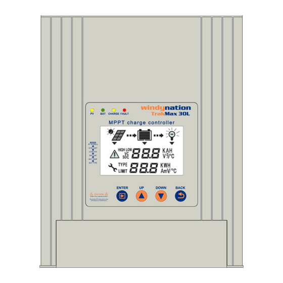
TrakMax 30L User Manual Revision 1.0 • B.SELECT Battery Type Selector • Battery • CHG.MODE Charge Mode • Photovoltaic • MPPT Maximum Power Point Tracking • Pulse Width Modulation 2 PRODUCT OVERVIEW The TrakMax solar charge controller is a 30 amp 12/24/48 Volt Maximum Power Point Tracking (MPPT) photovoltaic (PV) battery charge controller. -
Page 5: Specifications
TrakMax 30L User Manual Revision 1.0 Natural Cooling Silent, pulse width modulated (PWM), high efficiency operation Dual Battery Temperature Compensation; (Optional Requires item CHC-BTSC-02) Optional Remote Monitoring using (Requires item CHC-RMTR-01) Configurable charging current (10A, 20A, 30A) -
Page 6: Physical Specifications
TrakMax 30L User Manual Revision 1.0 Max Input Current 30 Amp Max Battery Charging Current 10, 20, or 30 Amp Load Current 10 Amp Max PV Open Circuit Array Voltage 150VDC Efficiency 97% @ full current Typical Idle Consumption < 160mA / 80mA / 40mA Bulk Charge 14.4V(default) -
Page 7: Electrostatic (Esd) Precautions
TrakMax 30L User Manual Revision 1.0 Important: Installations should meet all local codes and standards. Installations of this equipment should only be performed by skilled personnel such as licensed electricians and Certified Renewable Energy (RE) System Installers. Caution: Install the Solar charge controller in a dry, protected location away from sources of high temperature, moisture, and vibration. -
Page 8: Grounding
TrakMax 30L User Manual Revision 1.0 2) Place the controller mounting bracket on the desired mounting surface and mark the location of each keyhole (two per unit). 3) Secure the bracket using the two mounting screws (included). a) If wall anchors (included) are to be used, a pilot hole will be required at the drill mark. - Page 9 TrakMax 30L User Manual Revision 1.0 cables to the TrakMax until the TrakMax has been connected to the positive and negative terminals of the battery bank. It is recommended to use a strain relief (bushings, connectors, clamp connectors, or wire glands) in each of the three ¾...
- Page 10 TrakMax 30L User Manual Revision 1.0 Tighten Terminals Here Insert Wire/Cable Here a) Load: Maximum 10A DC Load • Connect a cable from the TrakMax terminal marked load negative (–) to the negative terminal of your DC load and tighten the screw.
-
Page 11: Overcurrent Protection
TrakMax 30L User Manual Revision 1.0 CAUTION: Risk of Fire and Shock Connect battery terminals prior to the connection of array terminals. 3.5 O VERCURRENT ROTECTION Circuit breakers or fuses must be installed in both the battery and solar circuits. The protection device ratings and installation methods must conform to NEC requirements. -
Page 12: Temperature Compensation
Automatic temperature compensation can be provided through use of the optional Temperature Sensor Kit (Part #: CHC-BTSC-02) that includes two temperature sensor cables and the required connector to interface with the TrakMax. Please contact your Windy Nation supplier for availability. 3.8.1... -
Page 13: Environment Temperature Sensor (Env)
TrakMax 30L User Manual Revision 1.0 When the BTS detects a temperature of 50 C (122 F) the TrakMax will stop the charge current until the temperature is within a safe operating zone. 3.8.2.1 BTS Installation 1) The BTS cable is 5m in length and has two plain wires on one end and lug on the other end. -
Page 14: Remote Monitor (Optional)
ONITOR PTIONAL Windy Nation offers an optional remote monitor (CHC-RMTR-01) that allows the user to monitor and configure the system from the remote LCD interface as opposed to the LCD interface located on the TrakMax. The Remote Monitor comes with a 5m cable and mounting bracket. -
Page 15: Communication Cable
TrakMax 30L User Manual Revision 1.0 3.9.1 Communication Cable The remote monitor uses RS485 communication via a standard 8-wire RJ45 telephone cable (straight-through, not a Null Modem / cross-over). If possible, pull the cable through conduit before crimping on the RJ45 connectors. -
Page 16: Operation
TrakMax 30L User Manual Revision 1.0 c. Slide the Monitor down until the monitor is secure in place. 2. Mounting Bracket (included) a. Secure the mounting bracket in desired location using two or three screws. b. Align the bracket locks on the bracket with the bracket locks on the rear of the monitor. -
Page 17: How Mppt Works
TrakMax 30L User Manual Revision 1.0 Current / Power vs. Voltage Characteristics 4.1.1 How MPPT Works A PV module is a constant current type device. As shown on a typical PV module voltage vs. current curve, current remains relatively constant over a wide range of voltage. A typical 75 watt module is specified to deliver 4.45 amps @ 17 volts @ 25 C cell temperature. -
Page 18: Button Definitions
TrakMax 30L User Manual Revision 1.0 PV input voltage present No input PV voltage BATTERY voltage present No BATTERY voltage CHARGE CHARGING in process No CHARGING FAULT FAULT or abnormality present Normal Operation 4.4 B UTTON EFINITIONS Button Name Description Enter into current parameter setting state. -
Page 19: Lcd Interface Cycle
TrakMax 30L User Manual Revision 1.0 ERROR Symbol. When present check the TrakMax controller and refer to Section 5 (Error Conditions) and 6 (Troubleshooting) PARAMETER SET Symbol When present in a particular interface, there is a user configurable parameter available. Press ENTER and the 4.6 LCD I... -
Page 20: Load Interface
TrakMax 30L User Manual Revision 1.0 BAT Indicator Battery Voltage Current Charging Limit Battery Current 4.7.3 Load Interface The value displayed in this interface is the output voltage and current from the controller to the load; i.e.: the current being consumed by the load (displayed in Amps). -
Page 21: Battery Type Interface
TrakMax 30L User Manual Revision 1.0 To set the Battery Temperature Compensation, press the ENTER key and hold for 3 seconds to enter setup mode. Once in setup mode will blink. Press the UP or DOWN keys to adjust to the desired value and press ENTER to save and return to main page. -
Page 22: Charge Mode
TrakMax 30L User Manual Revision 1.0 4.8 C HARGE 4.8.1 Three Stage Charge The TrakMax is configured for a three stage charging process, Bulk, Absorption, and Float. The three stage charge process provides a somewhat higher charge voltage to charge the battery quickly and safely. Once the battery is fully charged, a somewhat lower voltage is applied to maintain the battery in a fully charged state without excessive water loss. -
Page 23: Low Voltage Disconnect
30 seconds. If after restarting the controller the error remains, it may indicate a fatal error and will require you to contact the supplier or Windy Nation for warranty services. Error Code Description Possible Remedies •... -
Page 24: Troubleshooting And Support
TrakMax 30L User Manual Revision 1.0 • Check the battery voltage High Battery Voltage (>15.0V) • Check internal fuse for damage. • Restart the solar charge controller. High Charge Current • Adjust charging current • Check the DC load. High Load Current •... -
Page 25: Fuse Replacement
TrakMax 30L User Manual Revision 1.0 Charge OFF at high temperature • The system temporarily shuts down due to high heat sink temperatures. • Improve ventilation or reduce PV power to prevent over temp shut down. 6.3 F EPLACEMENT WARNING: Shock Hazard Verify that the solar input and battery breaker or disconnect has been opened (disconnected) before opening the controller. -
Page 26: Support
6.6 R ESTRICTIONS No warranty will apply if the Product (i) has been altered or modified except by Windy Nation; (ii) has not been installed, operated, repaired, or maintained in accordance with instructions supplied by Windy Nation; (iii) has been subjected to abnormal physical, thermal or electrical stress, misuse, negligence, or accident. If Windy Nation determines that the problem with the Product is not due to a manufacturing defect in Windy Nation’s... -
Page 27: Disclaimer
Some states do not allow the exclusion or limitation of incidental or consequential damages, so these limitations may not apply to you. Neither Windy Nation nor its affiliates or suppliers will be held liable or responsible for any damage or loss to any items or products connected to, powered by or otherwise attached to the Product. The total cumulative liability to Customer, from all causes of action and all theories of liability, will be limited to and will not exceed the purchase price of the Product paid by Customer. - Page 28 TrakMax 30L User Manual Revision 1.0 7 APPLICATION 7.1 B ATTERIES Batteries come in different sizes, types, amp-hour capacity, voltages and chemistries. Here are a few guidelines that will help in battery selection, and ensure that the batteries are properly maintained. The best source of the most appropriate settings for the TrakMax will be from the manufacturer or supplier of the batteries.
- Page 29 TrakMax 30L User Manual Revision 1.0 battery construction prevents measurement of the individual cell voltages, use a hydrometer. A variation of 0.020 in the specific gravity between cells is considered significant. Both conditions can be corrected by an equalization charge. A proper equalization charge will not damage a vented, liquid electrolyte type battery. It may, however, cause significant electrolyte usage and require that the battery be refilled with distilled water to the correct level.
Need help?
Do you have a question about the TrakMax 30L and is the answer not in the manual?
Questions and answers