Advertisement
Quick Links
SPX Corporation
5885 11th Street
Rockford, IL 61109-3699 USA
Internet Address:
http://www.powerteam.com
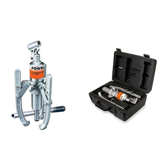
HYDRA-GRIP-O-MATIC PULLER KITS
NOTE:
•
These instructions must be read and carefully followed.
•
Carefully inspect the puller kit upon arrival. The carrier, not the manufacturer, is responsible for any
damage resulting from shipment.
WARNING: To help prevent personal injury,
•
These puller kits should be used only by trained personnel familiar with them.
•
Safety glasses must be worn at all times by the operator and anyone within sight of the puller.
•
Select the proper size and capacity of puller for the job.
•
Align the puller on the same centerline as the part being removed. Always have the jaws/studs adjusted
the same distance from the center of the tool (see Figure 1). Failure to align parts correctly can result in a
dangerous operating situation because of the high hydraulic pressures used.
•
Wrap the work in a Power Team protective blanket before applying pressure to provide protection from
injury caused by flying parts should a part ever break.
•
Always apply force gradually.
NOTE: The K83 puller kit has a 2/3-way combination puller crosshead. The 3-jaw combination is strongly
recommended whenever the job space allows for it. Three jaws give a more secure grip and more
even pulling force. The K82 and PH82K are equipped with a 2-way crosshead only!
1. Select the proper size and capacity of puller needed for the job. This is determined by measuring "reach" and
"spread" of the part to be pulled.
2. Place the handle assembly into the handle clevis. See Figure 1.
(Figure shown with
2-way crosshead
and studs)
© SPX Corporation
®
Tech. Services: (800) 477-8326
Fax: (800) 765-8326
Order Entry: (800) 541-1418
Fax: (800) 288-7031
Max. Capacity: 8 Ton
SAFETY PRECAUTIONS
PULLER SETUP AND OPERATION
Figure 1
Operating Instructions for:
R
(Figure shown with
3-way crosshead
and jaws)
Sheet No.
Rev.
Form No. 103501
K82
K83
PH82K
HANDLE
ASSEMBLY
HANDLE
CLEVIS
1 of 2
Date: 30 June 1999
Advertisement

Subscribe to Our Youtube Channel
Related Manuals for SPX HYDRA-GRIP-O-MATIC K82


Summary of Contents for SPX HYDRA-GRIP-O-MATIC K82
- Page 1 2. Place the handle assembly into the handle clevis. See Figure 1. (Figure shown with 3-way crosshead and jaws) (Figure shown with 2-way crosshead and studs) HANDLE ASSEMBLY HANDLE CLEVIS Figure 1 Sheet No. 1 of 2 Rev. Date: 30 June 1999 © SPX Corporation...
- Page 2 Operating Instructions, Form No. 103501, Back sheet 1 of 2 PULLER SETUP AND OPERATION (CONTINUED) Turn the control valve knob completely in a clockwise (Figure shown with direction to advance the piston. See Figure 2. 3-way crosshead and jaws) (Figure shown with 3-way crosshead and studs) IMPORTANT: Position...
- Page 3 Operating Instructions Form No. 103501 PULLER SETUP AND OPERATION (CONTINUED) The handle assembly rotates a full 360° to allow the best handle location for the job. See Figure 4. (Figure (Figure shown shown with 3-way with 3-way crosshead crosshead and jaws) and studs) Figure 4 Hold the puller with one hand and pump the handle with your other hand, advancing the piston until the part is...
- Page 4 Operating Instructions, Form No. 103501, Back sheet 2 of 2 PULLER SETUP AND OPERATION (CONTINUED) Turn the control valve knob completely in a counterclockwise direction to retract the piston. See Figure 7. (Figure shown with 3-way crosshead and jaws) CONTROL VALVE KNOB (Figure shown with 3-way crosshead...
Need help?
Do you have a question about the HYDRA-GRIP-O-MATIC K82 and is the answer not in the manual?
Questions and answers