Advertisement
Quick Links
Max. Capacity: 6 Ton (PH6 & PH63C); 8 Ton (PH8 & PH83C); 11 Ton (PH11, PH113C, & HST11);
NOTE:
•
These instructions must be read and carefully followed.
•
Carefully inspect the puller and/or straightener tool upon arrival. The carrier, not the manufacturer, is
responsible for any damage resulting from shipment.
WARNING: To help prevent personal injury,
•
These pullers and the straightener tool should be used only by trained personnel familiar with them.
•
Safety glasses must be worn at all times by the operator and anyone within sight of the puller and
straightener tool.
•
Select the proper size and capacity of puller for the job.
•
Align the puller on the same centerline as the part being removed. Failure to align parts correctly can
result in a dangerous operating situation because of the high hydraulic pressures used.
•
Wrap the work in a Power Team protective blanket before applying pressure to provide protection from
injury caused by flying parts should a part ever break.
•
Always apply force gradually.
IMPORTANT: DO NOT USE HEAT, HAMMERS, OR IMPACT TOOLS ON THESE PULLERS.
THIS WILL CAUSE DAMAGE THAT VOIDS THE PULLER WARRANTY.
NOTE: These pullers have a 2/3-way combination puller
head. The 3-jaw combination is strongly
recommended whenever the job space allows for
it. Three jaws give a more secure grip and more
even pulling force.
1. Select the proper size and capacity of puller needed for the
job. This is determined by measuring "reach" and "spread"
of the part to be pulled.
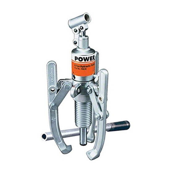
2. Place the handle assembly into the handle clevis.
See Figure 1.
© SPX Corporation
HYDRA-GRIP-O-MATIC
AND STRAIGHTENER TOOL
30 Ton (PH30 & PH303C)
SAFETY PRECAUTIONS
PULLER SETUP AND OPERATION
Form No. 102927
Parts List and
Operating Instructions for:
PULLER
®
Figure 1
Sheet No.
Rev 10
PH63C
PH83C
PH6
PH113C
PH8
PH303C
PH11
HST11
PH30
HST11S
HANDLE
ASSEMBLY
HANDLE
CLEVIS
1 of 5
Date: 30 Mar 2006
Advertisement


Need help?
Do you have a question about the Power Team HYDRA-GRIP-O-MATIC PH6 and is the answer not in the manual?
Questions and answers