Advertisement
Quick Links
SPX Corporation
5885 11th Street
Rockford, IL 61109-3699 USA
Internet Address:
http://www.powerteam.com
PUMP SECTION:
SINGLE SPEED WITH MECHANICAL RAPID ADVANCE,
PUMP OUTPUT .042 CU.IN. (.00069 LITER) PER STROKE.
HIGH PRESSURE RELIEF VALVE SET TO OPEN AT 10,400/10,000 PSI (716/689 BAR).
RESERVOIR CAPACITY, 4 7/8 CU.IN. (.08 LITER).
USABLE OlL, 3 3/4 CU.IN. (.06 LITER)
OIL TYPE USED, AMOCO RYKON MV.
HANDLE EFFORT, 4 1/8 LBS. (1.87 KG) PER 1000 PSI (68.9 BAR)
TOOL SECTION:
1.813 (4.605 CM) DIA.RAM, .912 (2.31 CM) STROKE WITH DIES.
REQUIRES 2.35 CU.IN. (.038 LITER) OIL MINIMUM.
CRIMPING FORCE, 26,332 LBS. (11,944 KG)
AT 10,200 PSI (702 BAR)
(13.1 TONS U.S., 11.89 TONS METRIC)
TOTAL WEIGHT, 13.6 LBS. (6.16 KG).
CRIMPING CAPACITY:
NO.6 THRU 750MCM CU, 500MCM AL.
(3 THRU 379.5 SQ.MM.CU, 253 SQ.MM.AL)
Litho in USA
®
Tech. Services: (800) 477-8326
Fax: (800) 765-8326
Order Entry: (800) 541-1418
Fax: (800) 288-7031
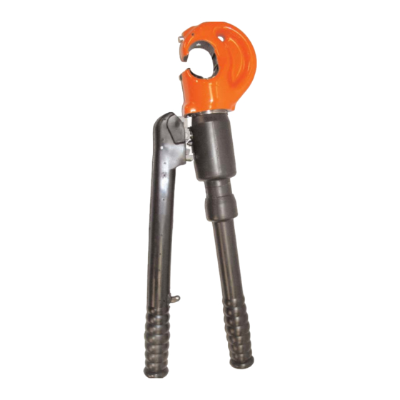
C12-TON HAND HYDRAULIC
COMPRESSION TOOL
INTRODUCTION
The C12-ton compression tool was designed for installing tubular
compression accessories on stranded electrical conductors. Twelve tons
thrust can be developed by this hand-operated compressor.
The compressor piston can be adjusted to a position that will require a
minimum of hand pumping to compress an accessory.
Twisting the pump handle clockwise will advance the piston until the
lower die-half contacts the accessory to be compressed. Compression is
completed by pumping the pump lever. When the die-halves touch the
compression is complete.
The piston is retracted by pulling the trigger on the pump lever and
making another pumping stroke. It will retract only to the positions
previously set, thus minimizing the amount of pumping needed to
complete the next compression.
Note that all operating controls are located such that the operator need
not remove his hands from the tool.
THE C12-TON TOOL IS NOT TO BE USED FOR "HOT LINE" WORK.
SPECIFICATIONS
Operating Instructions and
Parts List for:
WARNING
Sheet No.
Rev
Form No. 1000026
C12-TON-B
1 of 6
Date: 09 Feb 2004
Advertisement

Related Manuals for SPX POWER TEAM C12-TON


Summary of Contents for SPX POWER TEAM C12-TON
- Page 1 Form No. 1000026 ® Operating Instructions and Parts List for: SPX Corporation Tech. Services: (800) 477-8326 5885 11th Street Fax: (800) 765-8326 Rockford, IL 61109-3699 USA Order Entry: (800) 541-1418 Fax: (800) 288-7031 C12-TON-B Internet Address: http://www.powerteam.com C12-TON HAND HYDRAULIC...
-
Page 2: Important Safety Information
Operating Instructions and Parts List, Form No. 1000026, Back sheet 1 of 6 IMPORTANT SAFETY INFORMATION This is the safety alert symbol. WARNING To help prevent personal injury, It is used to alert you to potential personal injury • Always wear eye protection whenever hazards. - Page 3 Operating Instructions and Parts List, Form No. 1000026 OPERATING INSTRUCTIONS WARNING DO NOT OPERATE THE COMPRESSOR WITHOUT DIES. Select the proper dies for use on the accessory to be compressed. Push the die release button on the C-head and slide one of the identical die-halves into position. The die retainer pin locks the die in place. Insert the other die- half in the ram body by depressing the die release button located in a slight well in the ram.
-
Page 4: Servicing Instructions
Operating Instructions and Parts List, Form No. 1000026, Back sheet 2 of 6 SERVICING INSTRUCTIONS PREVENTIVE MAINTENANCE The majority of service troubles are caused by dirt collecting about the tool or in the oil system. Keep the tool clean and prevent foreign matter from entering the compressor while filling the reservoir. Lubricate all moving parts and keep the C-head stop screw, ram guide screw, and reservoir handle stop screw tightened. -
Page 5: Troubleshooting
Operating Instructions and Parts List Form No. 1000026 TROUBLE SHOOTING If the ram will not extend completely, it will generally be found that there is an insufficient amount of oil in the compressor's hydraulic system. This trouble can also be caused by faulty pump plunger packing or release valve packing by the pressure release valve being stuck open, or by foreign matter preventing the release valve balls from seating properly. -
Page 6: Parts List
Operating Instructions and Parts List, Form No. 1000026, Back sheet 3 of 6 PARTS LIST C12-TON Item Part Item Part Req’d Description Req’d Description 1000056 Label, 3-1197 Piston, Reservoir (Tradename Power Team) 1000055 Decal, 3-5071 Rubber Covering, Cylinder (Warning & Caution) 420691 Decal, 3-1201... - Page 7 Operating Instructions and Parts List Form No. 1000026 PARTS LIST SECTION C-C SECTION A-A SECTION B-B LEVER ASSEMBLY 3-1192 Item Part Item Part Req’d Description Req’d Description 3-1246 Lever 3-1253 Trigger 3-1248 Striker, Release 3-1254 Covering, Rubber, Lever 3-1249 Shaft 5-1265 3-1250 Bushing, Lever...
- Page 8 Operating Instructions and Parts List, Form No. 1000026, Back sheet 4 of 6 PARTS LIST SECTION A-A C-HEAD ASSEMBLY 3000094 Item Part Item Part Req’d Description Req’d Description 3-1237 Shaft, Die Release 3-1239 Spring 2000152 C-Head, Crimped 5-1265 Pin, Driv-lok 5-0662 Screw, Set 3-1238...
- Page 9 Operating Instructions and Parts List Form No. 1000026 PARTS LIST Stake Item 5 in place, Install Item 3 flush to .030 above surface and stake in place to prevent Rotation SECTION C-C SECTION E-E Apply 5-2538 adhesive to Tighten Item 16 to 35 Ft.Lbs. threads of Item 10 SECTION A-A SECTION B-B...
- Page 10 Operating Instructions and Parts List, Form No. 1000026, Back sheet 5 of 6 PARTS LIST SECTION A-A H.P. RELIEF VALVE ASSEMBLY 3-2716 Item Part Item Part Req’d Description Req’d Description 3-0654 Plunger, Valve 3-1233 Washer 3-1091 Screw, Adjusting 3-1234 Spring 3-1232 Body, Valve 5-1264...
- Page 11 Operating Instructions and Parts List Form No. 1000026 PARTS LIST RESERVOIR HANDLE ASSEMBLY 3-1196 Item Part Item Part Req’d Description Req’d Description 3-1255 Handle Sub-Assembly 3-1256 Plug, Res. Handle 3-1257 Covering, Handle (See below) Note: Use 5-2840 Adhesive to fasten spacer in place.
Need help?
Do you have a question about the POWER TEAM C12-TON and is the answer not in the manual?
Questions and answers