
Related Manuals for Juniper CSE2000


Summary of Contents for Juniper CSE2000
- Page 1 CSE2000 Hardware Installation Guide Published: 2014-03-20 Copyright © 2014, Juniper Networks, Inc.
- Page 2 END USER LICENSE AGREEMENT The Juniper Networks product that is the subject of this technical documentation consists of (or is intended for use with) Juniper Networks software. Use of such software is subject to the terms and conditions of the End User License Agreement (“EULA”) posted at http://www.juniper.net/support/eula.html.
-
Page 3: Table Of Contents
Power Specifications for the CSE2000 ........21... - Page 4 Connecting the CSE2000 to the Router ....... . . 57...
- Page 5 Returning CSE2000 Hardware for Repair or Replacement ....73 Locating CSE2000 Component Serial Numbers ......74 Chapter 18 Product Reclamation and Recycling .
- Page 6 Carrier-Grade Service Engine CSE2000 Hardware Installation Guide Copyright © 2014, Juniper Networks, Inc.
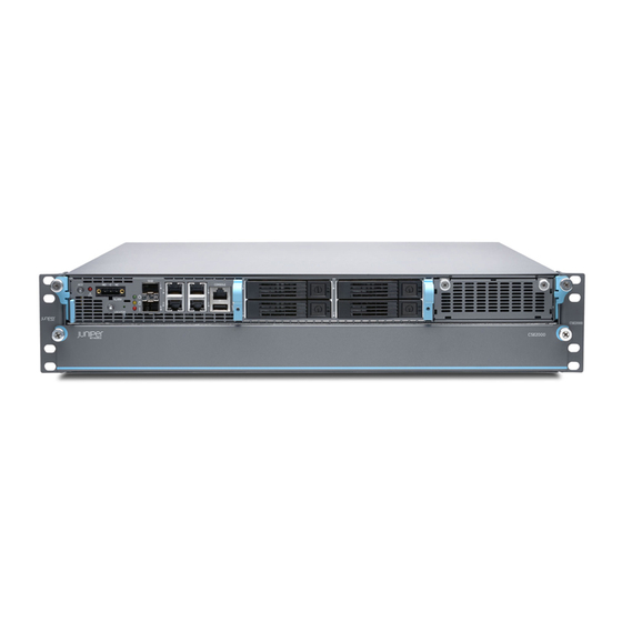
- Page 7 Figure 1: CSE2000 Front Panel Features ........
- Page 8 Carrier-Grade Service Engine CSE2000 Hardware Installation Guide Figure 19: Replacing an AC Power Supply ....... . 68 Figure 20: Removing a DC Power Supply .
- Page 9 Table 7: CSE2000 DC Power Supply LED ....... . 10...
- Page 10 Carrier-Grade Service Engine CSE2000 Hardware Installation Guide Copyright © 2014, Juniper Networks, Inc.
-
Page 11: About The Documentation
Junos OS Release Notes. ® To obtain the most current version of all Juniper Networks technical documentation, see the product documentation page on the Juniper Networks website at http://www.juniper.net/techpubs/ Documentation Conventions Table 1 on page xi defines the notice icons used in this guide. -
Page 12: Requesting Technical Support
7 days a week, 365 days a year. Self-Help Online Tools and Resources For quick and easy problem resolution, Juniper Networks has designed an online self-service portal called the Customer Support Center (CSC) that provides you with the following features: Find CSC offerings: http://www.juniper.net/customers/support/... -
Page 13: Carrier-Grade Service Engine Cse2000 Overview
PART 1 Carrier-Grade Service Engine CSE2000 Overview CSE2000 Description on page 3 Device Features and Specifications on page 5 Copyright © 2014, Juniper Networks, Inc. - Page 14 Carrier-Grade Service Engine CSE2000 Hardware Installation Guide Copyright © 2014, Juniper Networks, Inc.
-
Page 15: Cse2000 Description
PTX routers. After you connect the CSE2000 to a PTX5000 router, you can connect the CSE2000 to a third-party flow server for flow monitoring. Packets matching the policy criteria set for the ingress or egress interfaces on the PTX5000 router are sent to the CSE2000 device for flow monitoring. - Page 16 Field-replaceable, hot-swappable, and redundant fans and power supplies One USB port for each service card Two 10-Gigabit Ethernet with SFP+ ports Related CSE2000 Chassis Physical Specifications on page 10 Documentation Environmental Requirements and Specifications for CSE2000 on page 13 Copyright © 2014, Juniper Networks, Inc.
-
Page 17: Device Features And Specifications
Console interface One RJ-45 serial console port for each service card. x86-based service cards The CSE2000 can have one or two service cards, depending on requirement and configuration. USB interface Two USB ports, one for each service card, for software installation or reinstallation. -
Page 18: Cse2000 Front Panel Features
AC and DC power supplies are not supported simultaneously. CAUTION: The CSE2000 is NEBS compliant and the fan speed is optimized for balancing acoustic and cooling conditions based on the system configurations. Removing any dummy cover or removable component, such as tray or redundant power supply, changes the system air flow and might cause overheating of certain components. -
Page 19: Device Features And Specifications
Chapter 2: Device Features and Specifications Table 3: CSE2000 Front Panel Features (continued) Number Component Power button. This is a recessed button located behind a pinhole to prevent the CSE2000 from getting powered off accidentally. Alarm cut off ( ) button to deactivate alarms from the alarm relay, and this turns off the Alarm LED. -
Page 20: Table 5: Cse2000 Connectivity Ports
Carrier-Grade Service Engine CSE2000 Hardware Installation Guide Table 4: CSE2000 Front Panel LEDs (continued) LEDs Description Power The power LED (green) glows when the device is powered on and it is off when the device is powered off. Hard disk activity LED Hard disk activity LED (amber) glows when the service card is accessing the hard disk;... -
Page 21: Cse2000 Rear Panel Features
Removable AC or DC power supplies with LEDs. Figure 2 on page 9 shows AC power supplies. There are two AC or DC power supplies for each CSE2000. Chassis grounding studs to connect the grounding lug and cable. Figure 3 on page 10... -
Page 22: Cse2000 Chassis Physical Specifications
CSE2000 Chassis Physical Specifications The CSE2000 chassis is a rigid sheet-metal structure that houses the hardware components. Supports mounting in 19 inch rack; the CSE2000 can be mounted on a four-post rack or a two-post rack. Table 8 on page 10 summarizes the physical specifications of the CSE2000 chassis. -
Page 23: Planning
PART 2 Planning Site Preparation on page 13 Cable and Pinout Specifications on page 17 Planning Power Requirements on page 21 Compliance on page 23 Declaration of Conformity on page 25 Copyright © 2014, Juniper Networks, Inc. - Page 24 Carrier-Grade Service Engine CSE2000 Hardware Installation Guide Copyright © 2014, Juniper Networks, Inc.
-
Page 25: Site Preparation
Clearance Requirements for Airflow and Hardware Maintenance for the CSE2000 on page 15 CSE2000 Chassis Grounding Cable and Lug Specifications on page 15 Environmental Requirements and Specifications for CSE2000 The device must be installed in a rack housed in a dry, clean, well-ventilated, and temperature-controlled environment. -
Page 26: Rack Requirements For Cse2000
The CSE2000 must be installed into a rack that is secured to the building structure. Mount the CSE2000 at the bottom of the rack if it is the only unit in the rack. For the cooling system to function properly, the airflow around the chassis must be unrestricted. -
Page 27: Cse2000 Chassis Grounding Cable And Lug Specifications
General Safety Guidelines and Warnings for CSE2000 on page 31 Documentation CSE2000 Chassis Physical Specifications on page 10 Clearance Requirements for Airflow and Hardware Maintenance for the CSE2000 on page 15 Clearance Requirements for Airflow and Hardware Maintenance for the CSE2000 When planning the installation site, allow sufficient clearance around the rack. -
Page 28: Figure 4: Grounding Cable Lug
To meet safety and electromagnetic interference (EMI) requirements and to ensure proper operation, the CSE2000 must be adequately grounded before power is connected. Two bolts are provided at the rear of the chassis for connecting the router to earth ground. -
Page 29: Cable And Pinout Specifications
Documentation AC Power Cord Specifications for the CSE2000 Detachable AC power cords are supplied with the AC-powered CSE2000. The coupler is type C13 as described by International Electrotechnical Commission (IEC) standard 60320. The plug at the male end of the power cord fits into the power source outlet that is standard for your geographical location. -
Page 30: Table 11: Ac Power Cord Specifications For The Cse2000
SEV 1011 SEV 6534/2 United Kingdom 250 VAC, 10 A, 50 Hz BS 1363/A Related Connecting Power to AC-Powered CSE2000 on page 49 Documentation General Safety Guidelines and Warnings for CSE2000 on page 31 Copyright © 2014, Juniper Networks, Inc. - Page 31 Chapter 4: Cable and Pinout Specifications General Electrical Safety Guidelines and Warnings for CSE2000 on page 33 AC Power Electrical Safety Guidelines for CSE2000 on page 34 Prevention of Electrostatic Discharge Damage on CSE2000 on page 36 Copyright © 2014, Juniper Networks, Inc.
- Page 32 Carrier-Grade Service Engine CSE2000 Hardware Installation Guide Copyright © 2014, Juniper Networks, Inc.
-
Page 33: Planning Power Requirements
Power Specifications for the CSE2000 on page 21 Power Specifications for the CSE2000 This topic describes the power supply electrical specifications for the CSE2000. An AC power supply is standard, while a DC power supply is an available option. Table 12 on page 21... - Page 34 Carrier-Grade Service Engine CSE2000 Hardware Installation Guide Copyright © 2014, Juniper Networks, Inc.
-
Page 35: Compliance
CHAPTER 6 Compliance Agency Approvals for CSE2000 on page 23 CSE2000 Compliance Statements for NEBS on page 23 Agency Approvals for CSE2000 The CSE2000 device complies with the following standards: Safety CAN/CSA-C22.2 No. 60950-1 EN 60950 IEC 60950-1 UL 60950-1... - Page 36 Carrier-Grade Service Engine CSE2000 Hardware Installation Guide Related Agency Approvals for CSE2000 on page 23 Documentation Copyright © 2014, Juniper Networks, Inc.
-
Page 37: Declaration Of Conformity
CHAPTER 7 Declaration of Conformity Declaration of Conformity for CSE2000 on page 25 Declaration of Conformity for CSE2000 Figure 5 on page 26 shows the Declaration of Conformity for CSE2000. Copyright © 2014, Juniper Networks, Inc. -
Page 38: Figure 5: Cse2000 Declaration Of Conformity
Carrier-Grade Service Engine CSE2000 Hardware Installation Guide Figure 5: CSE2000 Declaration of Conformity Copyright © 2014, Juniper Networks, Inc. -
Page 39: Safety
PART 3 Safety General Safety Guidelines and Warnings on page 29 Electrical Safety Guidelines and Warnings on page 33 Copyright © 2014, Juniper Networks, Inc. - Page 40 Carrier-Grade Service Engine CSE2000 Hardware Installation Guide Copyright © 2014, Juniper Networks, Inc.
-
Page 41: General Safety Guidelines And Warnings
CHAPTER 8 General Safety Guidelines and Warnings Definition of Safety Warning Levels for CSE2000 on page 29 General Safety Guidelines and Warnings for CSE2000 on page 31 Definition of Safety Warning Levels for CSE2000 The CSE2000 documentation uses the following levels of safety warnings:... - Page 42 General Safety Guidelines and Warnings for CSE2000 on page 31 Documentation General Electrical Safety Guidelines and Warnings for CSE2000 on page 33 AC Power Electrical Safety Guidelines for CSE2000 on page 34 DC Power Electrical Safety Guidelines for CSE2000 on page 35...
-
Page 43: General Safety Guidelines And Warnings For Cse2000
Chapter 8: General Safety Guidelines and Warnings General Safety Guidelines and Warnings for CSE2000 The following guidelines help ensure your safety and protect the CSE2000 device from damage. The list of guidelines might not address all potentially hazardous situations in your working environment, so be alert and exercise good judgment at all times. - Page 44 Definition of Safety Warning Levels for CSE2000 on page 29 Documentation General Electrical Safety Guidelines and Warnings for CSE2000 on page 33 AC Power Electrical Safety Guidelines for CSE2000 on page 34 DC Power Electrical Safety Guidelines for CSE2000 on page 35...
-
Page 45: Electrical Safety Guidelines And Warnings
ESD point, and place the other end of the strap around your bare wrist. Failure to use an ESD strap could result in damage to the device. Install the CSE2000 in compliance with the following local, national, and international electrical codes: United States—National Fire Protection Association (NFPA 70), United States... -
Page 46: Ac Power Electrical Safety Guidelines For Cse2000
The power cord serves as the main disconnecting device for the device. The socket outlet must be near the device and be easily accessible. For CSE2000 devices that have more than one power supply connection, you must ensure that all power connections are fully disconnected so that power to the device is completely removed to avoid electric shock. -
Page 47: Dc Power Electrical Safety Guidelines For Cse2000
Definition of Safety Warning Levels for CSE2000 on page 29 Documentation General Safety Guidelines and Warnings for CSE2000 on page 31 General Electrical Safety Guidelines and Warnings for CSE2000 on page 33 Connecting Power to AC-Powered CSE2000 on page 49 DC Power Electrical Safety Guidelines for CSE2000... -
Page 48: Prevention Of Electrostatic Discharge Damage On Cse2000
Connecting Power to a DC-Powered CSE2000 Device on page 50 Prevention of Electrostatic Discharge Damage on CSE2000 The CSE2000 components that are shipped in antistatic bags are sensitive to damage from static electricity. Some components can be impaired by voltages as low as 30 V. - Page 49 Related Definition of Safety Warning Levels for CSE2000 on page 29 Documentation General Safety Guidelines and Warnings for CSE2000 on page 31 Connecting the CSE2000 Grounding Cable on page 47...
- Page 50 Carrier-Grade Service Engine CSE2000 Hardware Installation Guide Copyright © 2014, Juniper Networks, Inc.
-
Page 51: Installation
PART 4 Installation Preparing the Installation on page 41 Installing the CS2000 Device on page 43 Grounding the CSE2000 on page 47 Cabling on page 49 Powering On on page 53 Copyright © 2014, Juniper Networks, Inc. - Page 52 Carrier-Grade Service Engine CSE2000 Hardware Installation Guide Copyright © 2014, Juniper Networks, Inc.
-
Page 53: Preparing The Installation
Unpacking and Inspecting the CSE2000 on page 41 Before You Install the CSE2000 on page 42 Unpacking and Inspecting the CSE2000 The CSE2000 is shipped in a box. Quick Start installation instructions and a cardboard accessory box are also included in the shipping box. NOTE: The device is maximally protected inside the shipping box. -
Page 54: Before You Install The Cse2000
Read and understand the clearance requirements for the device to ensure adequate ventilation and enable access to the device for maintenance. See “Clearance Requirements for Airflow and Hardware Maintenance for the CSE2000” on page Have the tools and accessories needed to complete the installation. See “Unpacking and Inspecting the CSE2000”... -
Page 55: Installing The Cs2000 Device
Place the shipping container on a flat surface, and remove the hardware components with care. The CSE2000 can be installed in a two-post rack or a four-post rack. For two-post rack installations, see “Installing the CSE2000 in a Two-Post Rack” on page 44. -
Page 56: Installing The Cse2000 In A Two-Post Rack
Installing the CSE2000 in a Two-Post Rack CAUTION: Due to the size and weight of CSE2000—up to 60 lb (27.2 kg) with two service cards and 44 lb (20 kg) with one service card—we recommend that you install the device with two people (one to lift and one to secure the device to the rack). -
Page 57: Figure 7: Fixing Chassis Rack Rail
Figure 8: Installing the Chassis in a Four-Post Rack Related Before You Install the CSE2000 on page 42 Documentation Rack Requirements for CSE2000 on page 14 Clearance Requirements for Airflow and Hardware Maintenance for the CSE2000 on page 15 Copyright © 2014, Juniper Networks, Inc. - Page 58 Carrier-Grade Service Engine CSE2000 Hardware Installation Guide Copyright © 2014, Juniper Networks, Inc.
-
Page 59: Grounding The Cse2000
Make sure that grounding surfaces are clean before grounding connections are made. Connect the grounding cable to a proper earth ground. Verify that a licensed electrician has attached the cable lug provided with the CSE2000 device to the grounding cable. -
Page 60: Figure 9: Connecting The Grounding Cable
See Figure 9 on page 48 Verify that the grounding cable does not touch or block access to the CSE2000 components, and that it does not drape where people could trip on it. Figure 9: Connecting the Grounding Cable... -
Page 61: Cabling
Figure 10: Connecting AC Power Cord Related General Electrical Safety Guidelines and Warnings for CSE2000 on page 33 Documentation AC Power Electrical Safety Guidelines for CSE2000 on page 34 Copyright © 2014, Juniper Networks, Inc. -
Page 62: Connecting Power To A Dc-Powered Cse2000 Device
Carrier-Grade Service Engine CSE2000 Hardware Installation Guide Powering On the CSE2000 on page 53 Connecting Power to a DC-Powered CSE2000 Device Table 14: CSE2000 DC Power System Input Voltage Ports Description DC input voltage Operating range: –45 VDC to –60 VDC, 35.0 A max. -
Page 63: Connecting A Console Server To The Cse2000
Switch on the dedicated customer site circuit breaker for the power supply. Figure 11: Connecting DC Power Cables Related General Electrical Safety Guidelines and Warnings for CSE2000 on page 33 Documentation DC Power Electrical Safety Guidelines for CSE2000 on page 35... - Page 64 Carrier-Grade Service Engine CSE2000 Hardware Installation Guide Related RJ-45 Console Connector Pinout for the CSE2000 on page 17 Documentation Copyright © 2014, Juniper Networks, Inc.
-
Page 65: Powering On
You can use a small object that fits in the pinhole to press the power button. Monitor the LEDs on the CSE2000 to verify that the device is booting properly. The power LED is lit green when the CSE2000 is powered on. - Page 66 CSE2000. Here slot-number refers to the service cards in each slot, which can Press and quickly release the recessed power button in front of the chassis to power off the device.
-
Page 67: Configuration
PART 5 Configuration Connecting CSE2000 on page 57 Copyright © 2014, Juniper Networks, Inc. - Page 68 Carrier-Grade Service Engine CSE2000 Hardware Installation Guide Copyright © 2014, Juniper Networks, Inc.
-
Page 69: Connecting Cse2000
CSE2000. To connect the CSE2000 device to the PTX5000 router: Plug the appropriate cables to the 10-Gigabit Ethernet ports on CSE2000. Plug the other end of the cables to the 10-Gigabit Ethernet ports on the PICs installed in the FPC of the PTX5000. -
Page 70: Figure 13: Control Plane Connection Between Cse2000 And Ptx5000
ESC 0 ESC 1 NOTE: The command output is truncated. The CSE2000 is active and operational, and can be used after connecting the device to the router. Related CSE2000 Front Panel Features on page 6 Documentation... -
Page 71: Upgrading The Cse2000 Software Package
Chapter 15: Connecting CSE2000 Upgrading the CSE2000 Software Package Before you upgrade the software installed in the CSE2000, back up the currently running and active file system so that you can recover to a known, stable environment in case something goes wrong with the upgrade. For more information about the CSE2000 software, see the Flow Monitoring Feature Guide for CSE2000. -
Page 72: Activating The Locator Led
Carrier-Grade Service Engine CSE2000 Hardware Installation Guide Press the Enter key to copy the CSE2000 image to the USB drive. Insert the USB storage device with the latest software to a USB port in CSE2000. Access the CSE2000 using the port to install the software. -
Page 73: Maintenance
PART 6 Maintenance Maintaining Components on page 63 Packing and Returning Hardware on page 73 Product Reclamation and Recycling on page 75 Copyright © 2014, Juniper Networks, Inc. - Page 74 Carrier-Grade Service Engine CSE2000 Hardware Installation Guide Copyright © 2014, Juniper Networks, Inc.
-
Page 75: Maintaining Components
Maintaining Components Replacing a Service Card on the CSE2000 on page 63 Replacing a Hard Disk Drive on the CSE2000 on page 65 Replacing an AC Power Supply on the CSE2000 on page 67 Replacing a DC Power Supply on the CSE2000 on page 68... -
Page 76: Figure 14: Removing A Service Card
Carrier-Grade Service Engine CSE2000 Hardware Installation Guide CAUTION: As the service card is heavy, after it is unlocked, you must pull out the service card using the handles in the middle and not using the captive thumb screws. After you remove a service card, immediately place it on an antistatic mat or in an electrostatic bag. -
Page 77: Replacing A Hard Disk Drive On The Cse2000
Documentation Returning CSE2000 Hardware for Repair or Replacement on page 73 Replacing a Hard Disk Drive on the CSE2000 The CSE2000 supports Serial Attached SCSI (SAS) hard disks specified by Juniper Networks. CAUTION: Do not remove a hard disk drive when the CSE2000 device is powered on and operational. -
Page 78: Figure 16: Removing A Hard Disk Drive
Figure 17 on page 66 Power on the CSE2000. Figure 17: Replacing a Hard Disk Drive Related Powering Off the CSE2000 on page 53 Documentation Returning CSE2000 Hardware for Repair or Replacement on page 73 Copyright © 2014, Juniper Networks, Inc. -
Page 79: Replacing An Ac Power Supply On The Cse2000
CAUTION: The power supplies are redundant and you need not power down the CSE2000 if you are removing only one power supply. While removing a power supply, ensure that the other power supply and power cord are secured and that you do not accidently pull out the power supply or power cord. -
Page 80: Replacing A Dc Power Supply On The Cse2000
Insert the power cord into the inlet on the power supply. Insert the power cord into the AC power source outlet. The CSE2000 is powered on when you connect the power cable and the AC power source power outlet is switched on. -
Page 81: Figure 20: Removing A Dc Power Supply
Reconnect the grounding cable to the power supply. Turn on the site circuit breaker for the power supply. Figure 21: Replacing a DC Power Supply Related Powering Off the CSE2000 on page 53 Documentation Copyright © 2014, Juniper Networks, Inc. -
Page 82: Replacing A Cooling Fan On The Cse2000
Returning CSE2000 Hardware for Repair or Replacement on page 73 Replacing a Cooling Fan on the CSE2000 Each service card on the CSE2000 has six cooling fans that are hot-replaceable. See “CSE2000 Rear Panel Features” on page 9 for details. -
Page 83: Figure 23: Replacing A Cooling Fan
Insert the new fan and tighten the captive screw after the fan is fully seated. See Figure 23 on page Figure 23: Replacing a Cooling Fan Related Returning CSE2000 Hardware for Repair or Replacement on page 73 Documentation Copyright © 2014, Juniper Networks, Inc. - Page 84 Carrier-Grade Service Engine CSE2000 Hardware Installation Guide Copyright © 2014, Juniper Networks, Inc.
-
Page 85: Packing And Returning Hardware
CHAPTER 17 Packing and Returning Hardware Returning CSE2000 Hardware for Repair or Replacement on page 73 Locating CSE2000 Component Serial Numbers on page 74 Returning CSE2000 Hardware for Repair or Replacement When you need to return a component: Determine the part number and serial number of the component. See “Locating... -
Page 86: Locating Cse2000 Component Serial Numbers
Contacting Customer Support on page 79 Documentation Locating CSE2000 Component Serial Numbers Before contacting Juniper Networks to request a Return Materials Authorization (RMA), you must find the serial number on the chassis or component. Most components have a small rectangular serial number ID label (see Figure 24 on page 74) attached to the component body. -
Page 87: Product Reclamation And Recycling
Product Reclamation and Recycling Program on page 75 Product Reclamation and Recycling Program Juniper Networks is committed to environmentally responsible behavior. As part of this commitment, we continually work to comply with environmental standards such as the European Union’s Waste Electrical and Electronic Equipment (WEEE) Directive and Restriction of Hazardous Substances (RoHS) Directive. - Page 88 Our packaging is designed to be recycled and should be handled in accordance with your local recycling policies. Related Environmental Requirements and Specifications for CSE2000 on page 13 Documentation Copyright © 2014, Juniper Networks, Inc.
-
Page 89: Troubleshooting
PART 7 Troubleshooting Contacting Customer Support on page 79 Copyright © 2014, Juniper Networks, Inc. - Page 90 Carrier-Grade Service Engine CSE2000 Hardware Installation Guide Copyright © 2014, Juniper Networks, Inc.
-
Page 91: Contacting Customer Support
Closes the case when you agree that the problem has been resolved. Related Locating CSE2000 Component Serial Numbers on page 74 Documentation Returning CSE2000 Hardware for Repair or Replacement on page 73 Contacting Customer Support See the Juniper Networks Web site for complete customer service information: http://www.juniper.net/support/guidelines.html... - Page 92 From all other locations at 408-745-9500 Related Locating CSE2000 Component Serial Numbers on page 74 Documentation Information You Might Need to Supply to JTAC on page 79 Returning CSE2000 Hardware for Repair or Replacement on page 73 Copyright © 2014, Juniper Networks, Inc.
-
Page 93: Index
PART 8 Index Index on page 83 Copyright © 2014, Juniper Networks, Inc. - Page 94 Carrier-Grade Service Engine CSE2000 Hardware Installation Guide Copyright © 2014, Juniper Networks, Inc.
-
Page 95: Index
CSE2000 AC power CSE2000................6 connecting................49 CSE2000 grounding cable connecting................47 grounding cable CSE2000 installing CSE2000................15 four-post rack..............44 grounding instructions, CSE2000 two-post rack..............44 to prevent ESD..............36 customer support.............xii, grounding lug contacting JTAC...............xii CSE2000................15 information needed............79 Copyright © 2014, Juniper Networks, Inc. - Page 96 Carrier-Grade Service Engine CSE2000 Hardware Installation Guide grounding, CSE2000 return procedure, hardware site and rack preparation for........42 CSE2000................73 humidity (relative), acceptable safety guidelines and warnings, CSE2000 CSE2000................13 power................34 power................35 electrical................33 installation instructions, CSE2000........43 general.................31 prerequisites..............42 safety standards, CSE2000..........23 unpacking and inspecting the device......41...
- Page 97 Index warnings, CSE2000 power................34 power................35 electrical................33 general.................31 Copyright © 2014, Juniper Networks, Inc.
- Page 98 Carrier-Grade Service Engine CSE2000 Hardware Installation Guide Copyright © 2014, Juniper Networks, Inc.
Need help?
Do you have a question about the CSE2000 and is the answer not in the manual?
Questions and answers