Table of Contents
Advertisement
Quick Links
Advertisement
Table of Contents

Related Manuals for Jet JWS-20CS


Summary of Contents for Jet JWS-20CS
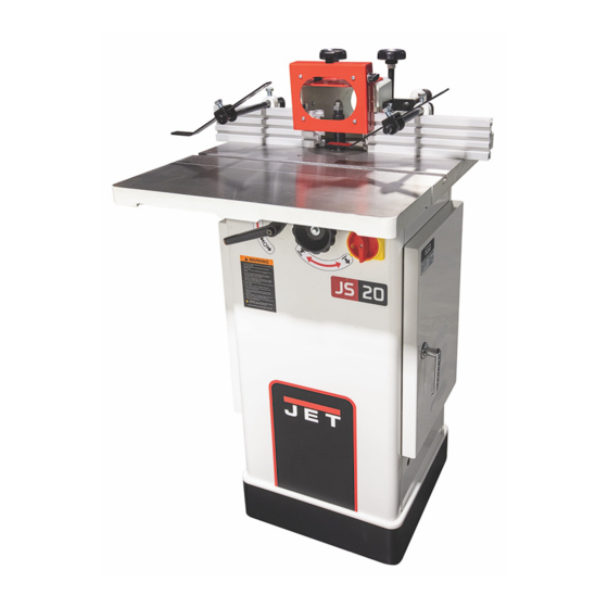
- Page 1 Operating Instructions and Parts Manual JWS-20CS Spindle Shaper Shown with optional extension table #724021 (ordered separately) 427 New Sanford Road LaVergne, Tennessee 37086 Part No. M-724020 Ph.: 800-274-6848 Edition 1 11/2022 www.jettools.com Copyright © 2022 JET...
- Page 2 JET sells through distributors only. The specifications listed in JET printed materials and on official JET website are given as general information and are not binding. JET reserves the right to effect at any time, without prior notice, those alterations to parts, fittings, and accessory equipment which they may deem necessary for any reason ®...
-
Page 3: Table Of Contents
JWS-20CS Spindle Assembly-Parts List ................. 21 JWS-20CS Fence Assembly-Exploded View ..............22 JWS-20CS Fence Assembly-Parts List ................23 JWS-20CS Safety Guard Assembly-Exploded View & Parts List ........24 JWS-20CS Extension Table-Exploded View & Parts List ..........25 JWS-20CS Electrical Connections .................. 26... -
Page 4: Warnings
Warning Wear eye protection. Be sure keyed washer is directly under the spindle nut and the spindle nut is tight. Feed the workpiece against the rotation of the cutter. Do not use awkward hand positions. Keep fingers away from the revolving cutter. Use fixtures when necessary. Use the overhead guard when the adjustable fence is not in place. - Page 5 • MAINTAIN TOOLS WITH CARE. Keep tools sharp and clean for best and safest performance. Follow instructions for lubricating and changing accessories. • ALWAYS DISCONNECT THE MACHINE FROM THE POWER SOURCE BEFORE SERVICING. • REDUCE THE RISK OF UNINTENTIONAL STARTING. Make sure the switch is in the off position before plugging in.
-
Page 6: Electrical Connections
This shaper has a cord/plug with a UL/CSA-listed cord/plug grounded three-prong electrical plug. designed for 230V operation (see Figure D). Contact your local Authorized JET Service must connect Center or a qualified electrician for proper electrical plug to a properly grounded, three- procedures to install the cord/plug. -
Page 7: Specifications
The JET JWS-20CS, as well as all JET products, are backed by a nationwide network of authorized distributors and/or service centers. Please contact your nearest distributor should you require parts or service. Parts are also available directly from JET by calling 1-800-274-6848. -
Page 8: Unpacking And Cleanup
Unpacking and Cleanup 1. Finish removing all contents from the shipping container. Do not discard any shipping material until the shaper is set up and running. 2. Inspect contents for shipping damage and report any damage or missing parts to your distributor. -
Page 9: Setup And Adjustment
Setup and Adjustments Spindle Removal and Installation adjustments machine must be made with the power off and unplugged from the power source. Failure to comply may result in serious injury. Figure 2 The spindle guard has been removed for illustration purposes only! Never operate the shaper without the spindle guard. -
Page 10: Fence Placement And Adjustment
4. Pull the spindle locking mandrel out (A, Figure 4) and turn to lock the main spindle. 5. Place collet assembly with draw bar into the main spindle. 6. Insert a router bit into the collet and tighten the draw bar nut (B, Figure 4). 7. -
Page 11: Operation
Operation Spindle Control To raise or lower spindle: 1. Loosen spindle lock handle (A, Figure 9). Turn handle counterclockwise to loosen. 2. Raise or lower spindle to desired height by turning handwheel (B, Figure 9). 3. Turn spindle lock handle clockwise to tighten. Figure 9 Using the Fence as a Guide Shaping with the fence is the safest and most... -
Page 12: Collar Positioning
Collar Positioning Collars may be positioned above, below, or between two cutters: 1. When using the collar below the cutter (Figure 17), you can always observe the progress of the cut. A disadvantage of this method is any Figure 15 accidental lifting of the work will gouge the wood and ruin the workpiece. -
Page 13: Starting Pin
Starting Pin Only experienced, advanced users should attempt starting pin shaping! If you have never used this method, get training from a qualified person who is knowledgeable in starting pin shaping! Failure to comply may cause serious injury! Place the starting pin in one of the two threaded holes in the table in front of the table rings. -
Page 14: Troubleshooting
Troubleshooting Trouble Probable Cause Remedy Cord unplugged from the power source. Plug in power cord. Fuse blown, or circuit breaker tripped. Replace fuse, or reset circuit breaker. Cord damaged. Replace cord. Shaper will not start. Reversing switch is in the OFF position. Turn switch to forward or reverse. -
Page 15: Replacement Parts
Number of your machine available when you call will allow us to serve you quickly and accurately. Non-proprietary parts, such as fasteners, can be found at local hardware stores, or may be ordered from JET. Some parts are shown for reference only and may not be available individually. -
Page 16: Jws-20Cs Base Assembly-Exploded View
JWS-20CS Base Assembly – Exploded View... -
Page 17: Jws-20Cs Base Assembly-Parts List
Description Size 1 ....JWS20-101 ....Cabinet ......................1 2 ....JWS20-102 ....JET Stripe ............... 98mm ......1 3 ....JWS20-103 ....Name Plate ....................1 4 ....JWS20-104 ....Cabinet Door ....................1 5 ....JWS20-105 ....Handle Assembly ..................1 6 .... -
Page 18: Jws-20Cs Motor Assembly-Exploded View
JWS-20CS Motor Assembly – Exploded View... -
Page 19: Jws-20Cs Motor Assembly-Parts List
JWS-20CS Motor Assembly – Parts List Index No Part No Description Size 1 ....JWS20-201 ....Spindle Bracket ..................... 1 2 ....JWS20-202 ....Gear Shaft ..................... 1 3 ....JWS20-203 ....Lock Handle ....................1 4 ....TS-0050051 ....Hex Cap Screw ............1/4-20 x 1 ...... 1 5 .... -
Page 20: Jws-20Cs Spindle Assembly-Exploded View
JWS-20CS Spindle Assembly – Exploded View... -
Page 21: Jws-20Cs Spindle Assembly-Parts List
JWS-20CS Spindle Assembly – Parts List Index No Part No Description Size 1 ....JWS25-301 ....Hex Nut ..............5/8 L.H......1 2 ....JWS25-302 ....Hex Nut ..............3/4 R.H ......1 3 ....JWS25-303 ....Spacer ..............3/4x1/2 ......1 4 .... -
Page 22: Jws-20Cs Fence Assembly-Exploded View
JWS-20CS Fence Assembly – Exploded View... -
Page 23: Jws-20Cs Fence Assembly-Parts List
JWS-20CS Fence Assembly – Parts List Index No Part No Description Size 1 ....JWS20-401 ....Knob ......................2 2 ....TS-0720091 ....Lock Washer ............3/8 ......... 4 3 ....TS-0570031 ....Hex Nut ..............3/8 ......... 2 4 .... -
Page 24: Jws-20Cs Safety Guard Assembly-Exploded View & Parts List
JWS-20CS Safety Guard Assembly – Exploded View JWS-20CS Safety Guard Assembly – Parts List Index No Part No Description Size ....JWS20-SGA ....Safety Guard Assembly (Item #23-#32) ............1 23 ....JWS20-623 ....Sliding Plate ....................1 24 .... -
Page 25: Jws-20Cs Extension Table-Exploded View & Parts List
JWS-20CS Extension Table Assembly (Option) – Exploded View JWS-20CS Extension Table Assembly (Option) – Parts List Index No Part No Description Size ....724021 ....... Extension Table Assembly (#1 thru #3) ............1 1 ....JWS20-501 ....Extension Table ..................... 1 2 .... -
Page 26: Jws-20Cs Electrical Connections
JWS-20CS Shaper Electrical Connections Electrical Schematic Electrical Schematic for the Forward/Reverse Switch... - Page 28 427 New Sanford Road LaVergne, Tennessee 37086 Phone: 800-274-6848 www.jettools.com...
Need help?
Do you have a question about the JWS-20CS and is the answer not in the manual?
Questions and answers