Table of Contents
Advertisement
Quick Links
Advertisement
Table of Contents

Related Manuals for Jet JWJ-8CS


Summary of Contents for Jet JWJ-8CS
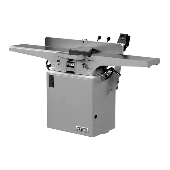
- Page 1 Operating Instructions and Parts Manual 8-inch Woodworking Jointer Models JWJ-8CS and JWJ-8HH Model JWJ-8CS Model JWJ-8HH 427 New Sanford Road LaVergne, Tennessee 37086 Part No. M-718200 Ph.: 800-274-6848 Edition 4 11/2019 www.jettools.com Copyright © 2016 JET...
-
Page 2: Warranty And Service
JET sells through distributors only. The specifications listed in JET printed materials and on official JET website are given as general information and are not binding. JET reserves the right to effect at any time, without prior notice, those alterations to parts, fittings, and accessory equipment which they may deem necessary for any reason whatsoever. -
Page 3: Table Of Contents
Parts List – Bed Assembly (all models) ....................23 Stand and Motor Assembly (JWJ-8CS only) ................... 24 Parts List – Stand and Motor Assembly (JWJ-8CS only) ................ 25 Stand and Motor Assembly (JWJ-8HH only) ................... 26 ... -
Page 4: Warning
5. Do not use this jointer for other than its intended use. If used for other purposes, JET disclaims any real or implied warranty and holds itself harmless from any injury that may result from that use. -
Page 5: Introduction
If there are any questions or comments, please contact either your local supplier or JET. JET can also be reached at our web site: www.jettools.com. -
Page 6: Levers And Controls
Shipping Weight, Jointer and Stand ..........452 lbs.......... 456 lbs The above specifications were current at the time this manual was published, but because of our policy of continuous improvement, JET reserves the right to change specifications at any time and without prior notice, without incurring obligations. -
Page 7: Setup And Assembly
Fence Handle Mounting Bolts 3/8" Lock Washers Operating Instructions and Parts Manual Warranty Card Tools Included with JWJ-8CS 12/14mm Open End Wrench 8/10mm Open End Wrench Hex Wrenches (3, 4 and 5 mm) Knife Gauge Assembly Tools included with JWJ-8HH... -
Page 8: Installing Bed To Stand
Do not use gasoline, paint thinner, mineral spirits, etc. These may damage painted surfaces. Cutterhead knives are dangerously sharp! Use extreme caution when cleaning. 4. Apply a thin layer of paste wax to the bright surfaces of the fence and tables to prevent rust. -
Page 9: Installing Handwheels
Figure 4 Assembling Knife-Setting Gauge (JWJ-8CS only) Place the two bases (A, Fig. 5) onto each end of the bar (B, Fig. 5). Snap the four E- rings (C, Fig. 4) into the grooves on the bar as shown, one E-ring on each side of a base. -
Page 10: Installing Cutterhead Guard
Installing Cutterhead Guard The cutterhead guard has a spring tension mechanism which must properly tensioned when installing the cutterhead guard on the machine. To install the cutterhead guard: 1. Insert a small hex wrench, or similar object, into the pin on the guard tension mechanism (Figure 8-1). -
Page 11: Installing Dust Chute
Figure 9 Model JWJ-8CS: Remove the cover of the switch box (A, Fig. 11) and mount the box to the right side of the stand using the two screws provided. Insert the motor leads through the hole in the stand as shown, and insert a grommet (B, Fig. -
Page 12: Adjustments
Recommended Extension Cord Gauges (AWG) Adjustments Extension Cord Length in Feet * Amps 90° Fence Adjustment Note: whenever making an adjustment to < 5 the fence, lift the fence up slightly after releasing lock handle avoid 5 to 8 scratching the table. 8 to 12 1. -
Page 13: Leveling Outfeed Table To Cutterhead Knives
After the outfeed table has been set, the JWJ-8HH will need no further adjustments to the cutterhead – skip steps 6 through 9 below. The JWJ-8CS must have its knives parallel with the outfeed table. Proceed as follows: 6. Bring the straight edge forward to the... -
Page 14: Removing And Replacing Knives (Jwj-8Cs Only)
(Fig. 21) Figure 22 illustrates the outfeed table at the correct height. Removing and Replacing Knives (JWJ-8CS only) Disconnect the machine from the power source before making any adjustment or repair. All knife lock... -
Page 15: Replacing Or Rotating Knife Inserts (Jwj-8Hh Only)
4. Before assembly, clean parts thoroughly and clear cutterhead knife slots of any dust or debris. 5. Insert knife into the cutterhead channel making sure it faces the proper direction. 6. Insert lock bar and screws and tighten to hold in place. Blades are set at the proper height when the top of the blade is 1/16"... -
Page 16: Infeed Table Depth Stop
Infeed Table Depth Stop Referring to Figure 26a: The infeed table travel limiter located on the back of the table sets the upper and lower range for the infeed table height adjustment and should not require any adjustments. The infeed table depth stop (A) limits the depth of a cut (set by adjusting the infeed table handwheel) to a maximum depth of 1/8”. -
Page 17: Jointing Warped Material
infeed table and the major flat surface of the workpiece against the fence (Fig. 28). Planing cuts are similar. The major surface of the workpiece is placed on the table with the narrow edge of the workpiece against the fence (Fig. 29). For jointing and planing cuts pressure is directed three ways;... -
Page 18: Bevel Cut
Bevel Cut To cut a bevel, lock the fence at the desired angle and run the material through, pressing the work firmly against the fence and tables (Fig. 31). Several passes may be necessary for the desired result. Taper Cut Taper cuts require the removal of the cutterhead guard. -
Page 19: Maintenance
To remove the cutterhead (including bearings, Sharpening Knives (JWJ-8CS only) studs, and housing) from the base casting: When blades become dull, touch up blades. 1. Disconnect the machine from the power source. -
Page 20: Replacement Parts
Feed wood more slowly. surface. Cutting blades are set too high above Readjust blades (JWJ-8CS). Kickbacks outfeed table, or they may not be level with outfeed table. (JWJ-8CS) Have motor checked by a qualified Motor Excessive motor repair station. noise. -
Page 21: Fence Assembly (All Models)
Fence Assembly (all models) Parts List – Fence Assembly (all models) Index No. Part No. Description Size 1 ....JWJ8CS-101 .... Fence Body ....................1 2 ....JC-F02 ..... Fence Link ....................1 3 ....TS-0051061 ..... Hex Head Screw ..........5/16”-18 x 1-1/4” ..1 4 .... -
Page 22: Bed Assembly (All Models)
Bed Assembly (all models) -
Page 23: Parts List - Bed Assembly (All Models)
41 ..... 5F-E208 ....Spring Pin ............. 5 x 28 ......1 42 ..... AP2-16 ..... Spring Pin ............. 6 x 28 ......1 43 ..... LM000185 ....I.D. Label (JWJ-8CS) ................1 ....LM000186 ....I.D. Label (JWJ-8HH) ................1 44 .... -
Page 24: Stand And Motor Assembly (Jwj-8Cs Only)
Stand and Motor Assembly (JWJ-8CS only) -
Page 25: Parts List - Stand And Motor Assembly (Jwj-8Cs Only)
27 ..... JJ8CS-327 ....Switch ....................... 1 28 ..... JJ8-923 ....Strain Relief....................1 29 ..... JET-138 ....JET Logo .............. 5-7/16” x 2-1/4” ... 1 30 ..... JC-T23 ..... Warning Label ..................1 31 ..... 5FK-C13 ....Key ............... 5x5x35 ......1 32 ..... -
Page 26: Stand And Motor Assembly (Jwj-8Hh Only)
Stand and Motor Assembly (JWJ-8HH only) -
Page 27: Parts List - Stand And Motor Assembly (Jwj-8Hh Only)
22 ..... TS-081F032 ..... Screw ..............1/4”-20x1/2” ....4 23 ..... JJ8-917W ....Motor ..............2HP, 1Ph ....1 29 ..... JET-138 ....JET Logo .............. 5-7/16” x 2-1/4” ... 1 30 ..... JC-T23 ..... Warning Label ..................1 31 ..... -
Page 28: Parts List - Cutterhead Assembly (Jwj-8Cs Only)
Parts List – Cutterhead Assembly (JWJ-8CS only) Index No. Part No. Description Size 1 ....JC-C01 ..... Cutterhead ....................1 2 ....JC-C02 ..... Bearing Housing ..................2 3 ....5H-A104 ....Bearing ..................... 2 4 ....JC-C03 ..... Cutterhead Set Bolt .................. 2 5 .... -
Page 29: Parts List - Cutterhead Assembly (Jwj-8Hh Only)
Parts List – Cutterhead Assembly (JWJ-8HH only) Index No. Part No. Description Size ....JJ8HH-CA ....Cutterhead Assembly (Index # 1 thru 11) ..........1 ....1791222-4 ....Helical Cutterhead Unit (Index # 1, 7, 8) ..........1 1 .... -
Page 30: Electrical Connections (Jwj-8Cs Only)
Electrical Connections (JWJ-8CS only) Motor... -
Page 31: Electrical Connections (Jwj-8Hh Only)
Electrical Connections (JWJ-8HH only) - Page 32 427 New Sanford Road LaVergne, Tennessee 37086 Phone: 800-274-6848 www.jettools.com...
Need help?
Do you have a question about the JWJ-8CS and is the answer not in the manual?
Questions and answers