
Related Manuals for Jet JWP-12L


Summary of Contents for Jet JWP-12L
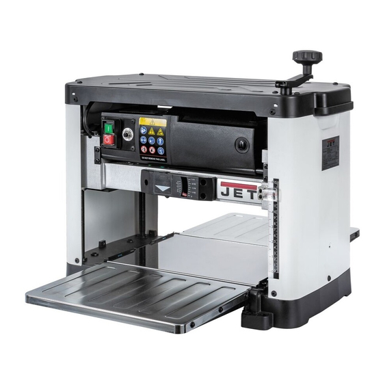
- Page 1 JWP-12L 12-1/2" Thicknesser with Straight Knife Cutterhead Original: Operating Instructions JPW (Tool) AG. Ackerstrasse 45, CH-8610 Uster, Switzerland Phone +41 44 806 47 48 +41 44 806 47 58 www.jettools.com M-10000847M 2020-01...
- Page 2 The drawings, illustrations, photographs, and specifications in this user manual represent your machine at time of print. However, changes may be made to your machine or this manual at any time with no obligation to JET.
- Page 3 PRODUCT SPECIFICATIONS Feed Speed M/min 7.92 Cutterhead Speed RPM 10,000 Motor RPM 23000+/-10% (No Load) Cutterhead Diameter 50.8mm Max. Planer Capacity 152mm x 318mm Max. Depth of Cut @ 6” 2.4mm Max. Depth of Cut @ 12-1/2” 1.6mm Minimum Length of Stock 178mm Minimum Thickness of Stock 4.76mm...
- Page 4 GENERAL SAFETY NOTE: The WARNING! and CAUTION! symbols indicate a potentially hazardous situation which, if not avoided, COULD result in death or serious injury. READ THIS MANUAL completely before assembling and operating this machine. WARNING! TO AVOID serious injury, death, or damage to the machine, please read, understand, and follow, all Safety and Operating Instructions before assembling and operating this machine.
- Page 5 GENERAL SAFETY ALWAYS keep the work area clean, well lit, and organized. DO NOT work in an area that has slippery floor surfaces from debris, grease, and wax. CAUTION! ALWAYS unplug the machine from the electrical receptacle when making adjustments, changing parts or performing any maintenance. AVOID ACCIDENTAL STARTING.
- Page 6 GENERAL SAFETY KEEP protective guards in place and in working order. CAUTION! MAINTAIN your balance. DO NOT extend yourself over the tool. Wear oil resistant rubber soled shoes. Keep floor clear of debris, grease, and wax. MAINTAIN all machines with care. ALWAYS KEEP machine clean and in good working order. KEEP all blades and tool bits sharp.
- Page 7 WARNING! DO NOT handle the plug or planer with wet hands USE only accessories as described in this manual and recommended by JET. 10. DO NOT pull the planer by the power cord. NEVER allow the power cord to come in contact with sharp edges, hot surfaces, oil or grease.
- Page 8 PRODUCT SAFETY 14. ENSURE that the machine sits firmly before using. If the machine wobbles or is unstable, correct the problem by using shims or blocks prior to operation. 15. This machine is designed to process wood ONLY. WARNING! NEVER position fingers or thumbs near the infeed/ outfeed rollers or cutterhead.
- Page 9 GROUNDING INSTRUCTIONS WARNING! This machine MUST BE GROUNDED while in use to protect the operator from electric shock. In the event of a malfunction or breakdown, GROUNDING provides the path of least resistance for electric current and reduces the risk of electric shock. The plug MUST be plugged into a matching electrical receptacle that is properly installed and grounded in accordance with ALL local codes and ordinances.
- Page 10 GROUNDING INSTRUCTIONS Make certain the extension cord is properly sized, and in good electrical condition. Always replace a worn or damaged extension cord immediately or have it repaired by a qualified person before using it. Protect your extension cords from sharp objects, excessive heat, and damp or wet areas.
- Page 11 If any parts are missing, do not attempt to plug in the power cord and run the machine. The machine should only be turned “ON” after all the parts have been obtained and installed correctly. For missing parts, contact JET. Raise / Lower Handle...
- Page 12 ASSEMBLY WARNING! MAKE CERTAIN THAT THE MACHINE IS DISCONNECTED FROM THE POWER SOURCE. ATTACHING DEPTH ADJUSTMENT HANDLE Attach the raise/lower adjustment handle (A) to the shaft (B) and fasten in place with 1 Hex Socket Head screw. Tighten screw using supplied hex wrench. SEE FIG 1. FIG 1 ATTACHING DUST PORT and ADAPTOR The Dust Port is to be used when the planer to be connected to a dust collector.
- Page 13 ASSEMBLY FIG 2A FIG 2B SECURING PLANER TO A TABLE OR WORKBENCH During operation, if there is any tendency for the planer to tip over, slide or walk, the planer MUST be secured to a supporting surface such as a workbench or table. Four holes are provided (2 are shown at (A)) to securely mount the planer.
- Page 14 ADJUSTMENTS WARNING! MAKE CERTAIN THAT THE MACHINE IS DISCONNECTED FROM THE POWER SOURCE BEFORE ANY ADJUSTMENTS ARE MADE. LEVELING EXTENSION TABLES The extension tables must be level with the planer table. To check the extension tables and adjust if necessary: Lay a straight edge (A) on the planer table (C) with one end of the straight edge over the infeed table (B).
- Page 15 ADJUSTMENTS RAISING AND LOWERING HEAD ASSEMBLY The head assembly consists of the cutterhead, knives, feed rollers, cutterhead guard, and the motor. Raising and lowering of the head assembly controls the depth of cut on the planer. To adjust: To raise the head assembly (A), turn the adjusting handle (B) clockwise. SEE FIG 5. To lower the head assembly, turn the adjusting handle counterclockwise.
- Page 16 ADJUSTMENTS REPLACING KNIVES FOR JWP-12L WARNING! MAKE CERTAIN THAT THE MACHINE IS DISCONNECTED FROM THE POWER SOURCE BEFORE ANY ADJUSTMENTS ARE MADE. WARNING! *** Be VERY CAREFUL when handling the knives or cutter tips as they are EXTREMELY SHARP and can cause serious injury!!! ***...
- Page 17 ADJUSTMENTS (Cont) FIG 6 FIG 7 KNIFE SHARP ANGLE FIG 8 FIG 9 THICKNESS SCALE ADJUSTMENT The thickness scale, located on the right of the planer, shows the thickness of the finished workpiece. To make sure the scale is set properly, run a piece of wood through the planer and measure the thickness of the wood.
- Page 18 OPERATIONS NOTE: This operations section was designed to give instructions on the basic operations of this planer. However, it is in no way comprehensive of every planer operation. It is strongly recommended that you read books, trade magazines, or get formal training to maximize the potential of your planer while minimizing the risks.
- Page 19 OPERATIONS DEPTH-OF-CUT INDICATOR The Depth-Of-Cut Indicator, located on the front of the machine, is a convenient way to quickly determine how much material is being planed off in one pass. With the machine OFF, insert your workpiece just under the cut scale (A). SEE FIG 11 Crank the raising / lowering handle until the button (B) comes in contact with the workpiece.
- Page 20 OPERATIONS THICKNESS PLANING Thickness planing sizes the workpiece to a desired thickness, while at the same time creating a smooth and level surface. The thickness of each cut will depend on the type of wood, width of the workpiece, and condition of the lumber (i.e. dryness, grain composition, straightness, etc). Always make thin test cuts on a scrap piece of wood prior to performing final cuts.
- Page 21 MAINTENANCE CAUTION! With the machine unplugged, blow off motor with low pressure air to remove dust or dirt. Air pressure above 50 P.S.I. should not be used as high-pressured air may damage insulation. The operator should always wear a respirator and eye protection when using compressed air.
- Page 22 MAINTENANCE Place a light coat of multi-purpose grease on the teeth of the gears (A) and a light coat of spray lubricant on the chain (B). Do not over-lubricate and replace the side panel. SEE FIG 13. FIG 13 Replace all covers, panels and guards, that you removed once lubrication is complete. BRUSH REPLACEMENT Brush life will vary depending on the load placed on the motor.
- Page 23 MAINTENANCE Once the brush has been removed, inspect the carbon (B), the spring (C), and the wire (D). SEE FIG 15. FIG 15 If the carbon of either brush is worn down to 4.76mm or less, both brushes should be replaced.
- Page 24 TROUBLESHOOTING GUIDE Motor and Machine Operation PROBLEM LIKELY CAUSE SOLUTION Snipe Dull cutter inserts Replace or turn cutter inserts. (depressions at Infeed or outfeed tables out of Readjust tables. Feed scrap of same end of workpiece) adjustment. thickness before and after Residue on rollers.
- Page 25 Exploded View for 10000847M...
- Page 26 Part List for 10000847M Index No Part No Description Size 1 ....JWP12L-01 ....Torx Wrench Assy ........... L145, T25 ...... 1 2 ....JWP12L-02 ....Hex Wrench ............. 4mm ......1 3 ....TS-2246082 ....Hex Socket HD Button Screw ........M6 x 8 ......15 4 ....
- Page 27 104 .... JWP12L-104 ..... Lift Indicating Label ..................1 110 .... JWP12L-110 ..... Motor Label ....................1 111 .... JET-92 ....... JET Logo Plaque ................... 1 112 .... JWP12L-112 ..... Base Guide Rail ..................... 2 113 .... JWP12L-113 ..... Pan Head Screw ............M4 x 6 ......12 114 ....
- Page 28 Wiring Diagram for 10000847M...
Need help?
Do you have a question about the JWP-12L and is the answer not in the manual?
Questions and answers