Table of Contents
Advertisement
Advertisement
Table of Contents

Related Manuals for Jet JHM-610


Summary of Contents for Jet JHM-610
- Page 1 Operating Instructions and Parts Manual Hobby Mill Model: JHM-610 WALTER MEIER (Manufacturing) Inc. 427 New Sanford Road LaVergne, Tennessee 37086 Part No. M-350200 Ph.: 800-274-6848 Revision A1 02/2011 www.waltermeier.com Copyright © 2011 Walter Meier (Manufacturing) Inc.
-
Page 2: Warranty And Service
Walter Meier is consistently adding new products to the line. For complete, up-to-date product information, check with your local Walter Meier distributor, or visit waltermeier.com. WARRANTY JET products carry a limited warranty which varies in duration based upon the product (MW = Metalworking, WW = Woodworking). WHAT IS COVERED? This warranty covers any defects in workmanship or materials subject to the exceptions stated below. -
Page 3: Table Of Contents
Table of Contents Warranty and Service..........................2 Table of Contents ..........................3 Warnings............................4 Specifications .............................6 Electrical ............................7 Unpacking ............................8 Shipping Contents ..........................8 Assembly ............................8 Mounting the Machine .........................8 Features ............................9 Operating Instructions ........................10 Routine Operating Instructions ....................... 10 Head Raiser ..........................10 Quill Feed ............................. -
Page 4: Warnings
Warnings 1. Read and understand the entire owner's manual before attempting assembly or operation. 2. Read and understand the warnings posted on the machine and in this manual. Failure to comply with all of these warnings may cause serious injury. 3. - Page 5 21. Make your workshop child proof with padlocks, master switches or by removing starter keys. 22. Give your work undivided attention. Looking around, carrying on a conversation and “horse-play” are careless acts that can result in serious injury. 23. Maintain a balanced stance at all times so that you do not fall or lean against the hobby mill or other moving parts.
-
Page 6: Specifications
Specifications Model Number ........................JHM-610 Stock Number .......................... 350200 Spindle stroke .......................1-3/16" (30mm) Maximum Distance, Spindle to Column ................5-1/2" (140mm) Swing Diameter ..........................11” Maximum Distance, Spindle Nose to Table..............10-1/2" (267mm) Maximum power .......................... 150W Spindle speeds ..............Low:100-1000 RPM; High:100-2000 RPM Maximum X Travel ..........................7"... -
Page 7: Electrical
The smaller the gage number, the heavier the cord. Electrical Connections The JHM-610 Hobby Mill is rated at 115V, 1PH. Volts Total length of cord in feet It is designed for use on a circuit with an outlet 120V that looks like the one shown in Fig. -
Page 8: Unpacking
Unpacking Assembly Carefully unpack the machine and inspect for Referring to Figure 1: damage. Any damage should be reported The Lifting Handwheel (14), Longitudinal Feed immediately to your distributor and shipping Handwheel (12), Cross Feed Handwheel (11), agent. Do not discard the carton or packing and Fine Feeding Handwheel (8) must be material until the machine is set up and running assembled prior to using the Hobby Mill. -
Page 9: Features
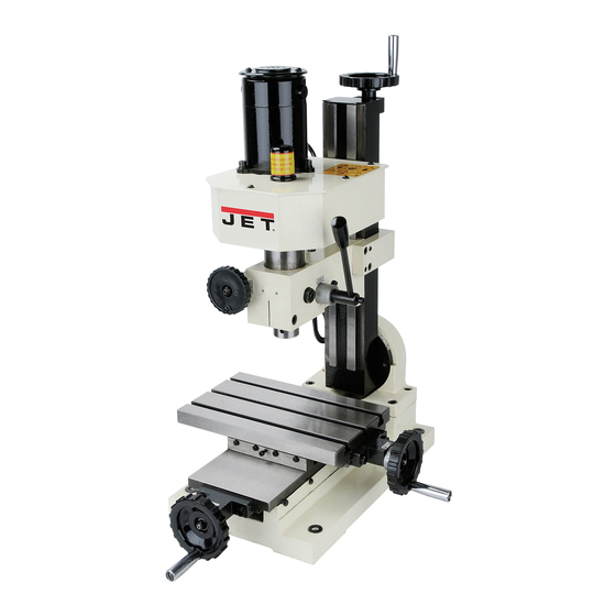
Features Figure 1 – Features 1 Forward/Off/Reverse Switch 09. Lock Handle 2. Variable Speed Control Knob 10. Work Table 3. Fuse Box 11. Cross Feed Handwheel 4. Power Light (Green) 12. Longitudinal Feed Handwheel 5. Yellow Light 13. Quill Feed 6. -
Page 10: Operating Instructions
Important: Do not attempt to turn the switch Operating Instructions directly from Forward to Reverse or from Reverse to Forward while the machine is Routine Operating Instructions running. To change the rotational direction, fist turn the switch to Off. After the machine stops While performing the steps listed below, refer to completely, select Forward of Reverse the Features Drawing (previous page) for... -
Page 11: Maintenance
Maintenance Always unplug the power cord before performing any inspection, maintenance, or cleaning. Before Each Use Inspect general condition machine. Check for loose screws, misalignment or binding of moving parts. Check for cracked or broken parts. Check for damaged electrical wiring. Check for any other condition that may affect its safe operation. -
Page 12: Assembly Drawing
Assembly Drawing... -
Page 13: Parts List
Parts List Index No. Part No. Description Size 1 ....TS-1532042 ....Pan Head Machine Screw .........M4x12......2 2 ....JHM610-02....Motor Cover ..................1 3 ....TS-1503031 ....Socket Head Cap Screw ........M6x12......3 4 ....TS-1551041 ....Lock Washer ............M6 ......3 5 .... - Page 14 Index No. Part No. Description Size 56 .... JHM610-56....Worm Base ..................1 57 .... JHM610-57....Worm Gear ..................1 58 .... JHM610-58....Spacer ....................1 59 .... JHM610-59....Pin ..............3x18 ......1 60 .... JHM610-60....Key ..............2x18 ......1 61 .... JHM610-61....Worm Shaft ..................1 62 ....
- Page 15 Index No. Part No. Description Size 126 ..JHM610-126....Control Label ..................1 127 ..JHM610-127....Screw ..............ST2.9x6.5 ....4 128 ..JHM610-128....Power Cord with Plug................1 129 ..JHM610-129....Caution Label ..................1 131 ..JHM610-131....Technical Parameter Label ..............1 ....JHM610-132....Drill Chuck (not shown) ............... 1 ....
-
Page 16: Wiring Diagram
Wiring Diagram...
Need help?
Do you have a question about the JHM-610 and is the answer not in the manual?
Questions and answers