Jet JWS-25X Operating Instructions Manual
Hide thumbs
Also See for JWS-25X:
- Specifications (4 pages) ,
- Specifications (2 pages) ,
- Features (3 pages)
Table of Contents

Related Manuals for Jet JWS-25X


Summary of Contents for Jet JWS-25X
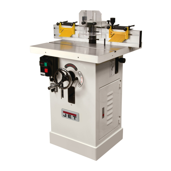
- Page 1 This .pdf document is bookmarked Operating Instructions and Parts Manual Model JWS-25X Shaper 427 New Sanford Road LaVergne, Tennessee 37086 Part No. M-708309 Ph.: 800-274-6848 Revision B 04/2017 www.jettools.com Copyright © 2017 JET...
-
Page 2: Warranty And Service
JET sells through distributors only. The specifications listed in JET printed materials and on official JET website are given as general information and are not binding. JET reserves the right to effect at any time, without prior notice, those alterations to parts, fittings, and accessory equipment which they may deem necessary for any reason ®... -
Page 3: Table Of Contents
Table of Contents Warranty and Service ............................ 2 Table of Contents ............................3 Warnings ............................... 4 Introduction..............................7 Specifications ..............................7 Optional Accessories ............................ 7 Pre-installation .............................. 8 Shipping Contents ............................8 Assembly ..............................10 Fence Casting ............................10 Fence ............................... 10 Featherboard ............................ -
Page 4: Warnings
5. Do not use this shaper for other than its intended use. If used for other purposes, JET disclaims any real or implied warranty and holds itself harmless from any injury that may result from that use. - Page 5 23. Use the right tool at the correct speed and feed rate. Do not force a tool or attachment to do a job for which it was not designed. The right tool will do the job better and safer. 24. Use recommended accessories; improper accessories may be hazardous. 25.
- Page 6 Short stock – Never shape stock less than 12 inches in length without special fixtures. Where practical, shape longer stock and cut to size. 12 inch rule – When shaping, never allow your hands to come closer than 12 inches to the cutters.
-
Page 7: Introduction
Introduction This manual is provided by JET covering the safe operation and maintenance procedures for a JET Model JWS-25X Shaper. This manual contains instructions on installation, safety precautions, general operating procedures, maintenance instructions and parts breakdown. This machine has been designed and constructed to provide consistent, long-term operation if used in accordance with instructions set forth in this manual. -
Page 8: Pre-Installation
Pre-installation Shipping Contents For maximum performance and safety from your Compare the contents of your container with the spindle shaper, clean and check it carefully parts listings and illustrations on this and before installation. following page to make sure all parts are intact. Missing parts, if any, should be reported to your Inspect the packing crate for physical or water distributor. - Page 9 Shipping Contents Hardware Hardware Hardware and included tools consist of the following items: Cutter Guard (C) Fence Lock Knob (P) 3/4" Spindle Assembly (D) Plastic Flat Washer (Q) 1/2" Spindle Assembly (E) Slide (R) Handwheel Handle (F) Spindle Wrench (S) Starting Pin (G) Crosspoint Driver (T) Lock Knob (H)
-
Page 10: Assembly
Assembly Fence Casting 1. Place the fence casting (B) onto the table of the cabinet (A). 2. Line up the threaded ends of the lock handles (B ) with the threaded mounting holes (A ) on the table. Tighten the lock handles but allow sufficient slack to permit the fence to be adjusted backward and forward. -
Page 11: Electrical Connections
The smaller the gauge number, the heavier the cord. A power plug is not provided with the Model JWS-25X. You may either connect the proper Extension Cord Length * UL/CSA listed plug or “hardwire” the machine directly to your electrical panel provided there is... -
Page 12: Adjustments
Adjustments When changing tools, making adjustments, or doing clean-up and maint- enance, always turn the machine off and unplug the machine from its power source. Fence Assembly Movement The adjustment controls of the fence assembly are as follows (refer to Figure 2): A –... -
Page 13: Changing Spindle Speed
Changing Spindle Speed Referring to Figure 4: The JWS-25X Shaper is equipped with pulleys that allow you to change the spindle speed. The drive belt (C) placed on the upper pulley position (A) provides a 7,500 RPM spindle speed. The belt placed on the lower pulley position (B) provides a 10,000 RPM spindle speed. -
Page 14: Coplanar Alignment
Coplanar Alignment Follow steps 1–5 to determine if alignment is necessary. Steps 6–9 will guide you through the alignment if required. Verifying that fences are coplanar Figure 5 1. Remove the guard and spindle attachment. 2. Unlock knobs D and adjust the fence assembly (A) so it is positioned approximately at midpoint;... -
Page 15: Ram Dial Calibration
Fence perpendicular to table The outfeed fence must also be perpendicular to the table. This can be checked as follows: 8. Place a square against the casting (L, Fig. 9) and table. 9. If adjustment is required, adjust setscrews (N, Fig. 9). Alignment is complete when both fence castings are coplanar (in-line) as shown in Figure 8 and the outfeed fence is perpendicular to the table. -
Page 16: Spindle Assembly Installation
Spindle Assembly Installation Referring to Figure 11: The spindle assembly (B) is mounted to the arbor (H) and secured with a draw bar (N) and spindle nut (D). Use the following procedure to install the spindle assembly. When changing tools, making adjustments, or doing clean-up and maint- enance, always turn the machine off and unplug the machine from its power source. -
Page 17: Shaper Cutter Installation
Shaper Cutter Installation Note: Spindle installation is described in the previous section. When changing tools, making adjustments, or doing clean-up and maint- enance, always turn the machine off and unplug the machine from its power source. Locking the Spindle 1. Locate the spindle lock directly above the cabinet door. -
Page 18: Featherboard Hold-Downs
Featherboard Hold-downs Referring to Figure 13: The JWS-25X Shaper comes equipped with two featherboard hold-downs (A, B) mounted on the infeed and outfeed fences. 1. Loosen lock handles (C) and lock knobs (D). 2. Slide the hold-down guides to the desired position along the fence and tighten the lock handles (C). -
Page 19: Operating Controls
4. Tighten the lock nut (H). Operating Controls Start/Stop Referring to Figure 15: The JWS-25X shaper is equipped with a pushbutton control system and reversing switch. The green start (A) and red stop (B) pushbuttons are mounted in a control enclosure on the front of the machine. -
Page 20: Operations
Operations Deep cuts require excessive horsepower and pushing force to control the Overview cut. Before applying power to the machine, Check the motor and switch wiring diagrams for proper Deep cuts can also cause the wood to splinter or voltage connections. Check that all mounting split and may lead to lost control or personal injury. - Page 21 Using the Fence Using the fence is the safest and most satisfactory method of shaping, and should always be used when the work permits. Almost all straight work can be used with the fence. For average work, where a portion of the original edge of the work is not to be touched by the cutter, Figure 19 both the front and rear fences are set in a straight...
- Page 22 "Z" Dimension Before making a template (or using the edge of the workpiece) for shaper cutting, the "Z" dimension must be established in order to determine the shape and size of the finished stock. The "Z" dimension is the difference between the innermost part of the cutter edge and the outside diameter of the ball bearing follower (collar).
- Page 23 Edge Shaping When edge shaping, never attempt to hand guide any stock less than 12 inches long, or narrower than 3 inches without the use of a special guide as shown in Figure 24. When edge shaping, the work- piece must be at least 12 inches long unless a special guide is used.
- Page 24 Straight Line Bevel Shaping Contour Edge Shaping With Collar Bearing To shape a beveled straight edge, use a bevel- To shape contoured edges, the operator must first edge shaping jig in combination with the regular remove the fence assembly. fence as shown in Figure 28. In order to control the workpiece and limit the depth-of-cut, the operator must use an anti-friction collar with the cutter(s) as shown in Figure 30.
- Page 25 If the workpiece is to be shaped all around the perimeter, hold it firmly and push the work straight into the cutter until the depth of cut is established by the collar as shown in Figure 33. Continue to feed the work so that the point of contact on the edge is always 90 degrees to the collar (or directly in line with the cutter edge) and held firmly against When the workpiece is not contoured all around,...
- Page 26 3. Using the collar between the two cutters has the advantages and disadvantages of the first two procedures, and is frequently used where both edges of the work are to be molded, Figure 38. Note: It is advisable to place the cutter as low as possible on the spindle to reduce spindle deflection Figure 38 and ensure the best possible finish.
- Page 27 Arcs and Circles Large circular and arc-shaped stock can be shaped as described in Contour Edge Shaping on page 24. However, smaller sized stock requires the use of special shaping jigs similar to those shown in Figure 41. With the entire fence assembly removed, carefully position the jig for desired depth-of-cut and securely clamp to the table.
- Page 28 Templates The template must be thick enough to provide a solid bearing edge against a collar. When constructing a template similar to the one shown in Figure 43, keep in mind that it serves only as a guide for the cutter. Figure 43 If the workpiece requires all-around shaping, the template can be constructed from several sections...
-
Page 29: Special Cuts
Special Cuts The illustrations in this section show the profile, or section, views made by the cutter(s). The most efficient cutters are carbide tipped to ensure clean and long-term cutting. Small cutters may be solid carbide, and some use inserts. Since there are such a wide variety of choices, the operator is limited only by his experience and imagination. - Page 30 Figure 52 shows BOTH cuts required for a window sash rail end. The first operation at top is a rabbet cut made with a groove cutter. The second operation is performed with a stub spindle and buttonhead screw. Butt Joints All butt-type joints require both work-pieces to be Figure 52 perfectly square and straight-edged.
- Page 31 Tenoning The tenoning fixture illustrated in Figure 57 shows a miter gauge equipped with a hold-down for shaping the ends of narrow work-pieces. The miter gauge can also be adapted to cut square and centered tenons at the ends of legs for tables, chairs, etc.
-
Page 32: Troubleshooting
Troubleshooting Trouble Possible Cause Remedy 1. Cord unplugged from the power 1. Plug in power cord. Shaper will not start. source. 2. Fuse blown or circuited breaker 2. Replace fuse or reset circuit tripped. breaker. 3. Cord damaged. 3. Replace cord. 4. -
Page 33: Parts
Serial Number of your machine available when you call will allow us to serve you quickly and accurately. Non-proprietary parts, such as fasteners, can be found at local hardware stores, or may be ordered from JET. Some parts are shown for reference only, and may not be available individually. -
Page 34: Table – Parts And Assembly
Table – Parts and Assembly Index No. Part No. Description Size 1 ....JWS25X-101 .... Insert Ring (Small) ................... 1 2 ....JWS25X-102 .... Insert Ring (Large) ................... 1 3 ....JWS25X-103 .... Table ......................1 4 ....JWS25X-104 .... Starting Pin....................1 5 .... -
Page 35: Fence - Parts List
Fence – Parts List Index No. Part No. Description Size 1 ....JWS35X-201 .... Knob ......................4 2 ....PM2700-237 .... Feather Board ..................2 3 ....PM2700-234 .... Bracket ..................... 2 4 ....TS-1550061 ..... Flat Washer ............M8 ....... 4 5 .... -
Page 36: Fence - Assembly Drawing
Fence – Assembly Drawing... -
Page 37: Frame And Motor - Parts List
Frame and Motor – Parts List Index No. Part No. Description Size 1 ....JWS25X-301 .... Motor Bracket ................... 1 2 ....TS-0270051 ..... Socket Set Screw ..........5/16”-18x1/2” ....1 3 ....JWS25X-303 .... Hex Cap Screw ............ 1/2”-12x2” ....1 4 .... -
Page 38: Frame And Motor - Assembly Drawing
Frame and Motor – Assembly Drawing... -
Page 39: Cabinet And Base - Parts And Assembly
26 ..... JWS25X-426 .... ID Label ....................1 27 ..... JWS25X-427 .... Scale Label ....................1 28 ..... JWS25X-428 .... JET Logo ....................1 29 ..... JWS25X-429 .... Plate ......................1 30 ..... TS-0680021 ..... Flat Washer ............1/4” ......2 31 ..... -
Page 40: Elevator - Parts And Assembly
Elevator – Parts and Assembly Index No. Part No. Description Size 1 ....JWS25X-501 .... Housing ....................1 2 ....TS-0720111 ..... Lock Washer ............1/2” ......3 3 ....JWS25X-503 .... Hex Cap Screw ............ 1/2”-12x1-1/2” ..... 3 4 .... -
Page 41: Quill - Parts And Assembly
Quill – Parts and Assembly Index No. Part No. Description Size 1 ....JWS25X-601 .... Quill ......................1 2 ....JWS25X-602 .... Spindle Holder ..................1 3 ....JWS25X-603 .... Retaining Ring ............. STW-30 ....... 1 4 ....TS-0207031 ..... Socket Head Cap Screw ........1/4”-20x5/8 ....6 5 .... -
Page 42: Spindle Assembly - Parts And Assembly
Spindle Assembly – Parts and Assembly Index No. Part No. Description Size 1 ....TS-0208061 ..... Socket Head Cap Screw ........5/16”-18x1” ....1 2 ....JWS25X-702 .... Special Washer ..................1 3 ....JWS25X-703 .... Keyed Collar..................... 1 4 .... -
Page 43: Wiring Diagram
Wiring Diagram... - Page 44 427 New Sanford Road LaVergne, Tennessee 37086 Phone: 800-274-6848 www.jettools.com...
Need help?
Do you have a question about the JWS-25X and is the answer not in the manual?
Questions and answers