Table of Contents
Advertisement
Quick Links
This .pdf document is bookmarked
Operating Instructions and Parts Manual
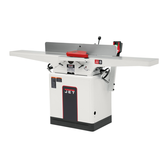
8-inch Woodworking Jointer
Models JWJ-8CS and JWJ-8HH
Model JWJ-8HH shown
JET
427 New Sanford Road
Part No. M-718200
LaVergne, Tennessee 37086
Edition 5 11/2020
Ph.: 800-274-6848
ECR 20110408438
www.jettools.com
Copyright © 2016 JET
Advertisement
Table of Contents

Related Manuals for Jet JWJ-8HH


Summary of Contents for Jet JWJ-8HH
- Page 1 This .pdf document is bookmarked Operating Instructions and Parts Manual 8-inch Woodworking Jointer Models JWJ-8CS and JWJ-8HH Model JWJ-8HH shown 427 New Sanford Road Part No. M-718200 LaVergne, Tennessee 37086 Edition 5 11/2020 Ph.: 800-274-6848 ECR 20110408438 www.jettools.com Copyright © 2016 JET...
-
Page 2: Warranty And Service
JET sells through distributors only. The specifications listed in JET printed materials and on official JET website are given as general information and are not binding. JET reserves the right to effect at any time, without prior notice, those alterations to parts, fittings, and accessory equipment which they may deem necessary for any reason whatsoever. -
Page 3: Table Of Contents
Parts List – Stand and Motor Assembly (JWJ-8CS only) ................ 25 Stand and Motor Assembly (JWJ-8HH only) ................... 26 Parts List – Stand and Motor Assembly (JWJ-8HH only) ................ 27 Parts List – Cutterhead Assembly (JWJ-8CS only) ................. 28 ... -
Page 4: Warning
5. Do not use this jointer for other than its intended use. If used for other purposes, JET disclaims any real or implied warranty and holds itself harmless from any injury that may result from that use. -
Page 5: Introduction
If there are any questions or comments, please contact either your local supplier or JET. JET can also be reached at our web site: www.jettools.com. -
Page 6: Levers And Controls
Shipping Weight, Jointer and Stand ..........452 lbs.......... 456 lbs The above specifications were current at the time this manual was published, but because of our policy of continuous improvement, JET reserves the right to change specifications at any time and without prior notice, without incurring obligations. -
Page 7: Setup And Assembly
12/14mm Open End Wrench 8/10mm Open End Wrench Hex Wrenches (3, 4 and 5 mm) Knife Gauge Assembly Tools included with JWJ-8HH 12/14mm Open End Wrench 8/10mm Open End Wrench Hex Wrenches (3, 4, 5, 6 mm) Star Point Screwdrivers... -
Page 8: Installing Bed To Stand
Do not use gasoline, paint thinner, mineral spirits, etc. These may damage painted surfaces. Cutterhead knives are dangerously sharp! Use extreme caution when cleaning. 4. Apply a thin layer of paste wax to the bright surfaces of the fence and tables to prevent rust. -
Page 9: Installing Handwheels
Installing Handwheels 1. Remove protective tape from shaft, and remove screw and washer. 2. Press handwheel (A, Fig. 4) onto shaft, aligning the keyway with the key. necessary, use a hammer with a block wood handwheel completely onto the shaft. 3. -
Page 10: Installing Cutterhead Guard
Installing Cutterhead Guard The cutterhead guard has a spring tension mechanism which must properly tensioned when installing the cutterhead guard on the machine. To install the cutterhead guard: 1. Insert a small hex wrench, or similar object, into the pin on the guard tension mechanism (Figure 8-1). -
Page 11: Installing Dust Chute
Consult the wiring diagram inside the switch box cover. The diagram is also on page 30 of this manual. The JWJ-8CS and JWJ-8HH jointers are rated at 230V, single phase only. Confirm that the power at the source is compatible... -
Page 12: Adjustments
Recommended Extension Cord Gauges (AWG) Adjustments Extension Cord Length in Feet * Amps 90° Fence Adjustment Note: whenever making an adjustment to < 5 the fence, lift the fence up slightly after releasing lock handle avoid 5 to 8 scratching the table. 8 to 12 1. -
Page 13: Leveling Outfeed Table To Cutterhead Knives
2. Rotate the cutterhead by turning the cutterhead pulley and determine the 12 o’clock position of knife number one (or a knife insert on the JWJ-8HH model). The 12 o’clock position is the highest point a blade will reach in the cutting arc. -
Page 14: Removing And Replacing Knives (Jwj-8Cs Only)
7. If blade is higher or lower at one point, slightly loosen five screws (A, Fig. 19) by turning clockwise as viewed from the infeed table. 8. Place the knife setting gauge (B, Fig. 19) on the cutterhead over the blade. Continue loosening the five screws until the springs push the knife up into contact with the gauge. -
Page 15: Replacing Or Rotating Knife Inserts (Jwj-8Hh Only)
12 of this manual. Replacing or Rotating Knife Inserts (JWJ-8HH only) The knife inserts on the model JWJ-8HH Jointer are four-sided. When dull, simply remove each insert, rotate it 90° for a fresh edge, and re-install it. -
Page 16: Infeed Table Depth Stop
Infeed Table Depth Stop Referring to Figure 26a: The infeed table travel limiter located on the back of the table sets the upper and lower range for the infeed table height adjustment and should not require any adjustments. The infeed table depth stop (A) limits the depth of a cut (set by adjusting the infeed table handwheel) to a maximum depth of 1/8”. -
Page 17: Jointing Warped Material
infeed table and the major flat surface of the workpiece against the fence (Fig. 28). Planing cuts are similar. The major surface of the workpiece is placed on the table with the narrow edge of the workpiece against the fence (Fig. 29). For jointing and planing cuts pressure is directed three ways;... -
Page 18: Bevel Cut
Note: Rabbet cuts are not applicable with complete the cut. the Model JWJ-8HH Jointer with helical head. 1. Adjust the fence so that the distance between the end of the knives and fence is equal to the width of the rabbet (Fig. -
Page 19: Maintenance
7. Take the same amount of passes for all three blades. Maintenance When the blades have been sharpened, if they still are not cutting efficiently, trying to touch up Lubrication the blades further will only cause the formation 1. Use a good grade of light grease on the of a second beveled edge. -
Page 20: Replacement Parts
7. Before replacing the cutterhead back into 8. To re-install the cutterhead, reverse the the casting, thoroughly clean the “saddle” above steps. and the bearing housings of saw dust and grease so that they seat properly. Troubleshooting Trouble Probable Cause Remedy Finished stock is Raise outfeed table so it is level with... -
Page 21: Fence Assembly (All Models)
Fence Assembly (all models) Parts List – Fence Assembly (all models) Index No. Part No. Description Size 1 ....JWJ8CS-101 .... Fence Body ....................1 2 ....JC-F02 ..... Fence Link ....................1 3 ....TS-0051061 ..... Hex Head Screw ..........5/16”-18 x 1-1/4” ..1 4 .... -
Page 22: Bed Assembly (All Models)
Bed Assembly (all models) -
Page 23: Parts List - Bed Assembly (All Models)
42 ..... AP2-16 ..... Spring Pin ............. 6 x 28 ......1 43 ..... LM000185 ....I.D. Label (JWJ-8CS) ................1 ....LM000186 ....I.D. Label (JWJ-8HH) ................1 44 .... TS-0270051 ..... Set Screw ............. 5/16”-18 x 1/2” .... 1 45 .... -
Page 24: Stand And Motor Assembly (Jwj-8Cs Only)
Stand and Motor Assembly (JWJ-8CS only) -
Page 25: Parts List - Stand And Motor Assembly (Jwj-8Cs Only)
27 ..... JJ8CS-327 ....Switch ....................... 1 28 ..... JJ8-923 ....Strain Relief....................1 29 ..... JET-815T ....JET Logo .............. 8” x 15” ......1 30 ..... JC-T23 ..... Warning Label ..................1 31 ..... 5FK-C13 ....Key ............... 5 x 5x 35 ..... 1 32 ..... -
Page 26: Stand And Motor Assembly (Jwj-8Hh Only)
Stand and Motor Assembly (JWJ-8HH only) -
Page 27: Parts List - Stand And Motor Assembly (Jwj-8Hh Only)
22 ..... TS-081F032 ..... Screw ..............1/4”-20x1/2” ....4 23 ..... JJ8-917W ....Motor ..............2HP, 1Ph ....1 29 ..... JET-815T ....JET Logo .............. 8” x 15” ......1 30 ..... JC-T23 ..... Warning Label ..................1 31 ..... -
Page 28: Parts List - Cutterhead Assembly (Jwj-8Cs Only)
Parts List – Cutterhead Assembly (JWJ-8CS only) Index No. Part No. Description Size 1 ....JC-C01 ..... Cutterhead ....................1 2 ....JC-C02 ..... Bearing Housing ..................2 3 ....5H-A104 ....Bearing ..................... 2 4 ....JWJ8CS-304 .... Plate ......................2 5 .... -
Page 29: Parts List - Cutterhead Assembly (Jwj-8Hh Only)
Parts List – Cutterhead Assembly (JWJ-8HH only) Index No. Part No. Description Size ....JJ8HH-CA ....Cutterhead Assembly (Index # 1 thru 11) ..........1 ....1791222-4 ....Helical Cutterhead Unit (Index # 1, 7, 8) ..........1 1 .... - Page 30 Electrical Connections (JWJ-8CS only) Motor...
-
Page 31: Electrical Connections (Jwj-8Hh Only)
Electrical Connections (JWJ-8HH only) - Page 32 427 New Sanford Road LaVergne, Tennessee 37086 Phone: 800-274-6848 www.jettools.com...
Need help?
Do you have a question about the JWJ-8HH and is the answer not in the manual?
Questions and answers