
Related Manuals for Aseptico ADU-17X Express II


Summary of Contents for Aseptico ADU-17X Express II
- Page 1 OPERATION and MAINTENANCE INSTRUCTION MANUAL ADU-17X Express II Portable Dental System...
-
Page 2: Table Of Contents
Street S.E. • Woodinville, WA 98072 Figures 2a thru 2e - Changing Voltage . .4 International (425) 487-3157 • Toll Free(800) 426-5913 www.aseptico.com • info@aseptico.com Figure 3 - Installing Instrument Holder . . .5 Figure 4 - Waste Tank Connections ..5 Figure 5 - Saliva Ejector Connection . -
Page 3: Package Contents
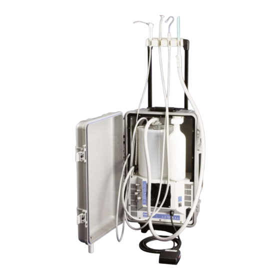
Your new Aseptico Express II Portable Dental System is the finest portable electric dental system available. The ADU-17X features a handpiece control, 3-way air/water syringe, HVE and saliva ejector vacuum systems, a self contained water system, oilless air compressor, and vacuum pump. -
Page 4: Safety Precautions
SAFETY PRECAUTIONS: Aseptico accepts no liability for direct or consequential injury or damage resulting from improper use, arising in particular through the non-observance of the operating instructions, or improper preparation and maintenance. WARNING: Sterilize before first and all uses. Clean, disinfect, and sterilize new or repaired instru- ments before first use. - Page 5 SETTING UP THE UNIT: FIG. 1 - ADU-17X Express II CLIP-ON INSTRUMENT HOLDER 3-WAY AIR/WATER SYRINGE HANDPIECE HIGH VOLUME VACUUM VOLUME (HVE) VACUUM (SALIVA EJECTOR) CASE WASTE HANDLE TANK TIE-DOWN RESERVOIR CONNECTOR WATER HANDPIECE SUPPLY ON/OFF BOTTLE SWITCH COOLANT WASTE...
-
Page 6: Setting Up The Unit
SETTING UP THE UNIT Cont’d 1. Unpack the ADU-17X Case. 2. Verify that the Voltage Selector Insert is Fig. 2b Fig. 2a configured properly by checking the voltage indicator on the Voltage Selector Module (Figure 2a). The Voltage Module is located on the lower left of the Motor Cover. - Page 7 3. Mount the clip-on Holder to the extended handle of the front of the Waste Tank. Connect the Low the Case, as shown in Figure 3. Volume Vacuum (Saliva Ejector) hose to the black connector located on the front of the Tank. Fig.
-
Page 8: Operation Functions
OPERATION FUNCTIONS: 1. FOOT SWITCH RUN MODE: b.) Release pressure from Bottle by slightly All Express II System components are activated loosening bottle from reservoir connector by the on/off Foot Switch. The Foot Switch approximately 1/8-turn, or by depressing the enables the operation of the handpiece, high air button on the 3-Way Syringe. -
Page 9: Operation
OPERATION: 3. CONTINUOUS RUN MODE: After you have set up the Express II unit and have become familiar with its functions, a. Turn the Run Mode Switch on the front enable one of the following two Run Modes: of the Fan Housing to the •... -
Page 10: Sterilization & Maintenance
STERILIZATION AND MAINTENANCE: Because of its simple design, the Aseptico ADU-17X Express II requires very little maintenance. Any maintenance that is needed can be performed in minutes. BLEEDING THE SYSTEM If the unit will not be used for an extended period of time, or the unit might be subjected to freezing conditions, you should bleed the system. -
Page 11: Troubleshooting
TROUBLESHOOTING: Problem: Correction: Unit will not start Check system’s power connection. Turn Run Mode Switch to “Continuous” or “Foot Switch” Mode and begin operation. Check that voltage selector module is set for source voltage. Check fuse. If blown, replace with 6.3A/125V medium time delay fuse for 120V operation, or a 4A/250V slo-blo fuse for 230V operation. -
Page 12: Repacking Instructions
REPACKING INSTRUCTIONS: 1. Remove all accessories from the unit. FIG. 10 2. Remove water bottle and place in travel pouch provided. 3. Position syringe in its holder on left side of case (Fig. 10). Lay tube behind syringe, next to waste tank. 4. -
Page 13: Symbol Definitions
SYMBOL DEFINITIONS: Type B Equipment Protective earth (ground) IPX1 Warning—Potential danger to Protect Against Dripping Water patient or user (consult accom- panying documents) Serial Number Dangerous Voltage Foot Switch Alternating current On/Off Switch Handpiece - Air Adjustment Switches Coolant Cavitron Connector This symbol indicates that the waste of electrical and electronic Fuses... -
Page 14: Specifications
SPECIFICATIONS: Size: 10.5” x 14.5” x 24” (27 cm x 36 cm x 61 cm) 1.81 cu. ft. (0.05 m 3) Volume: Weight: 43.5 lbs (19.7 kg) Power Source: AC Dual Voltage Manual-Switching 120V / 230V at 50Hz / 60Hz Current Rating: 6.3A at 120 VAC, or 4A at 230 VAC... -
Page 15: Warranty
In the event of alleged defect under warranty, the purchaser is to notify Aseptico's Customer Service Department promptly. Customer Service will provide instructions, usually directing that the product be returned for service. Shipment to Aseptico and the cost thereof is always the responsibility of the purchaser. - Page 16 P.O. Box 1548 • Woodinville, WA 98072 8333 216th Street SE • Woodinville, WA 98072 (425) 487-3157 • (800) 426-5913 www.aseptico.com • info@aseptico.com P/N: 420627 Rev. L ECO 14117 PRINTED IN 03/2017 THE U.S.A.
Need help?
Do you have a question about the ADU-17X Express II and is the answer not in the manual?
Questions and answers