
Subscribe to Our Youtube Channel
Related Manuals for Winco 35-75 PTO


Summary of Contents for Winco 35-75 PTO
- Page 1 35-75 PTO GENERATORS INSTALLATION AND OPERATORS MANUAL WINCO INC. 225 S. CORDOVA AVE. LE CENTER, MN 56057 507-357-6821 SERVICE DEPT. 507-357-6831 www.wincogen.com...
-
Page 2: Table Of Contents
Should you experience a problem please follow the “Troubleshooting Tables” near the end of this manual. The warranty listed in the manual OPERATION describes what you can expect from WINCO should you need service PRE-START CHECKS assistance in the future. -
Page 3: Safety Information
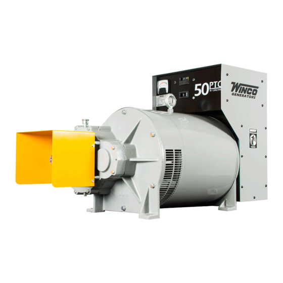
50PTOC-3 1. ELECTRICAL SHOCK - Watts 50,000 The output voltage present in this equipment can cause fatal electric Phase Single shock. This equipment must be operated by a responsible person. Voltage 120/240 Power Factor A. Do not allow anyone to operate the generator without proper Amps instruction. -
Page 4: Testing Policy
Trailer, for Portable Operation let WINCO take care of the freight claim. If you sign for the unit, the 8. Strip the insulation off the free end of each of the plug leads... -
Page 5: Electrical Connections
operation, even though the mechanical design of the tumbling bar The bag contains an instruction sheet, 2 plug bodies, four contacts, would allow greater misalignment. a handle and the hardware to assembly the disconnect plug. You will need to purchase the appropriate length of fine stranded copper D. -
Page 6: Operation
plug leads (cables) are being connected is not energized (live). To aid in determining how much load can be applied to the generator, and how it should be distributed among the generator output Strip the insulation off of the free end of each of the plug leads (cables) receptacles, the following formulas may be useful. -
Page 7: Generator Procedures
240 to from Winco are always synchronized and tethered so they can not be 5. Plug load cord set into receptacle. Place transfer switch in 245 volts, in green portion of voltmeter scale. -
Page 8: Maintenance
frequency will have to be monitored closely and manually adjusted. SHUTDOWN 1. Switch off electrical load. Check the generator gear case oil level before each use of the generator. Maintain the oil level at oil level plug height. The generator is 2. -
Page 9: Trouble Shooting Tables
GENERATOR STORAGE 2. Remove cooling fan shroud. Vacuum or blow dust from screen and fan blades. Wipe them off with cleaning solvent if necessary. Before storing the generator, apply a heavy coat of grease to the 3. Vacuum or blow dust and other debris from inside generator and splined input shaft. -
Page 10: Wiring Diagrams
WIRING DIAGRAMS 35PTOC-3 & 50PTOC-3 40PTOC-4 & 75FPTOC-4 REV B 60706-198... - Page 11 45PTOC-17 & 75FPTOC-17 60706-198 REV B...
-
Page 12: Month Limited Warranty
36 MONTH LIMITED WARRANTY WINCO, Inc., warrants for thirty-six months from date of shipment, that it will repair or replace at its option, for the original user, the whole or any part of the product found upon examination, by WINCO at its factory at 225 South Cordova Avenue, Le Center, Minnesota, or by any factory-authorized service station, to be defective in material or workmanship under normal standby use (average less than 50 hours per month) and service.
Need help?
Do you have a question about the 35-75 PTO and is the answer not in the manual?
Questions and answers