
Subscribe to Our Youtube Channel
Related Manuals for Winco W100PTOS


Summary of Contents for Winco W100PTOS
- Page 1 Tractor Drive PTO Generators OWNERS MANUAL INSTALLATION AND OPERATION INSTRUCTIONS W100PTOS W105PTOT W135PTOS W145PTOT W150PTOS SAFETY FIRST READ THIS MANUAL BEFORE OPERATING YOUR GENERATOR. 60706-160...
-
Page 2: Table Of Contents
COPY YOUR MODEL AND SERIAL NUMBER HERE To get the best performance from your new generator No other WINCO generator has the same serial number as set, it is important that you carefully read and follow the yours. It is important that you record the number and other operating instructions in this manual. -
Page 3: Guide To Product Safety
DEADLY EXHAUST GAS - Exhaust fumes from any engine SAFETY INFORMATION contain carbon monoxide, an invisible, odorless and deadly gas that must be mixed with fresh air. This generator set has been designed and manufactured to allow safe, reliable performance. Poor maintenance, a. -
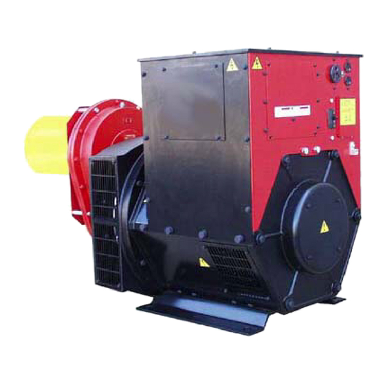
Page 4: Description
Contact the carrier for claim procedures. The WINCO PTO drive generator will provide, depending on the unit purchased, 120/240V single phase, 120/240V three When loss or damage is noted after delivery, segregate the... -
Page 5: Installation
Model Insulation Misalignment must be less than 15 degrees during generator operation, even though the mechanical design of the tumbling W100PTOS Neoprene/THHN bar may allow greater misalignment. W105PTOT Neoprene/THHN B. The foundation must be solid enough to absorb generator... -
Page 6: Electrical Connections
D. The generator mounting area of the trailer bed should be Wiring must conform to all applicable national, state, and local flat. All four generator mounting pads must rest firmly on the codes. (Reference: National Fire Protection Association trailer bed. Install shims if necessary to even out the bed Manual No. -
Page 7: Operation
THE GENERATOR IS ON STANDBY, AND MUST ISOLATE MOTOR LOAD SINGLE PHASE THREE PHASE THE COMMERCIAL POWER LINES FROM THE LOAD AND Motor Amps Amps Amps Amps THE GENERATOR WHEN THE GENERATOR IS SUPPLYING Horsepower 115V 230V POWER. SEE FIGURE 5. (Running Amps) (Running Amps) Operation... -
Page 8: Starting Procedure
6. Make sure that the electrical loads to be powered by the generator will not exceed the current ratings of the generator, receptacle, or cord set which will supply the current. 7. Check all electrical connections in the system to be energized by the generator. -
Page 9: Maintenance
5. Shut off the engine. NOTE: Do not over lubricate the universal joints. 4. Disconnect drive shaft (tumbling bar) power take-off end first, then generator end. See Figure 8 for recommended lubrication schedule for the coupling shaft. MAINTENANCE Check the generator gear case oil level before each use of the generator. -
Page 10: Cleaning
2. Remove cooling fan shroud. Vacuum or blow dust from 5. Replace the oil level check plug. screen and fan blades. Wipe them off with cleaning solvent if necessary. 6. Replace the breather. 3. Vacuum or blow dust and other debris from inside genera- CLEANING &... - Page 11 SYMPTOM CAUSE(S) CORRECTIVE ACTION High voltage. Defective or misadjusted AVR Adjust, repair or replace as required. Output voltage Tumbling bar (coupling shaft) Reduce tumbling bar misalignment to less than 15 degrees. flickering or misalignment. fluctuation. Engine speed not constant. Engine governor may be worn or improperly adjusted. Set or repair defective governor.
-
Page 12: Generator Connections 120/240 Volt Single Phase
GENERATOR CONNECTIONS 120/240 VOLT SINGLE PHASE GENERATOR CONNECTIONS 120/240 VOLT THREE PHASE 3117-20 Page 10 60706-160... -
Page 13: 120/208 Volt Three Phase
GENERATOR CONNECTIONS 120/208 VOLT THREE PHASE GENERATOR CONNECTIONS 277/480 VOLT THREE PHASE 3117-20 60706-160 Page 11... -
Page 14: Generator Receptacle Panels
GENERATOR RECEPTACLE PANEL W100PTOS-3 GENERATOR RECEPTACLE PANEL W105PTOT-4 W105PTOT-17 GENERATOR RECEPTACLE PANEL W105PTOT-18 3117-20 Page 12 60706-160... -
Page 15: Convenience Receptacle Wiring
GENERATOR RECEPTACLE PANEL ON MODELS W135PTOS-3 W145PTOT-4 W145PTOT-17 W150PTOS-3 GENERATOR RECEPTACLE PANEL ON MODEL W145PTOT-18 GENERATOR CONVENIENCE RECEPTACLE WIRING ON ALL MODELS EXCEPT 480 VOLT UNITS 3117-20 60706-160 Page 13... -
Page 16: Month Warranty
36 MONTH LIMITED WARRANTY WINCO, Inc., warrants for thirty-six months from date of shipment, that it will repair or replace at its option, for the original user, the whole or any part of the product found upon examination, by WINCO...
Need help?
Do you have a question about the W100PTOS and is the answer not in the manual?
Questions and answers