Table of Contents
Advertisement
Quick Links
Advertisement
Table of Contents

Related Manuals for Viavi CAA06M


Summary of Contents for Viavi CAA06M
- Page 1 CAA06M Cable and Antenna Analyzer User’s Guide...
-
Page 3: Table Of Contents
Environmental specifications ....................... 10 Options ..............................11 Getting Started ............................13 Unpacking and inspecting CAA06M Cable and Antenna Analyzer ............13 Installing CAA06M Cable and Antenna Analyzer ..................13 Installing CAA06M to mainframe ......................13 Glancing at menus and icons ........................14 Menus on the side bar ......................... - Page 4 Table of Contents Using save ............................15 Creating a report ..........................16 Using event save ..........................17 Using quick save ..........................17 Using create favorite ..........................17 Using load ............................18 Using file manager ..........................18 Using auto naming file ..........................19 Saving using auto naming file ......................
- Page 5 CAA06M Cable and Antenna Analyzer Preparing for a measurement ........................31 Selecting measurement mode ......................31 Setting parameters ..........................31 Making a measurement ........................... 33 Procedure ............................33 Analyzing measurement results ......................34 DTF Testing..............................39 Introduction .............................. 39 Introducing DTF measurements ......................39 Preparing for a measurement ........................
- Page 6 Table of Contents Preparing for a measurement ........................56 Selecting measurement mode ......................56 Setting parameters ..........................56 Making a measurement ........................... 58 Procedure ............................58 Analyzing measurement results ......................59 Cable Delay Testing ............................ 60 Introduction .............................. 60 Introducing cable delay measurements ....................60 Preparing for a measurement ........................
- Page 7 CAA06M Cable and Antenna Analyzer Gain..............................73 Insertion loss ............................73 Preparing for a measurement ........................74 Selecting measurement mode ......................74 Setting parameters ..........................74 Making a measurement ........................... 77 Procedure ............................77 Analyzing measurement results ......................77 CW Signal Generating ..........................79 Introduction ..............................
- Page 8 Table of Contents Running a test ............................88 Creating a report ............................90 Analysis ............................... 93 Introduction .............................. 93 Using zoom zones ........................... 93 Setting sub-band frequency ......................... 93 Tips for zoom zones ..........................93 Using alternate DTF band ........................94 Setting alternate DTF band ........................
-
Page 9: About Caa06M Cable And Antenna Analyzer
Copyright/Trademarks © Copyright 2022 VIAVI Solutions Inc. All rights reserved. VIAVI and the VIAVI logo are trademarks of VIAVI Solutions Inc. (“VIAVI”). All other trademarks and registered trademarks are the property of their respective owners. -
Page 10: Safety And Compliance Information
About CAA06M Cable and Antenna Analyzer The CAA06M Cable and Antenna Analyzer includes third party software licensed under the terms of separate open source software licenses. By using this software you agree to comply with the terms and conditions of the applicable open source software licenses. Software originated by VIAVI is not subject to third party licenses. - Page 11 VIAVI has established a take-back processes in compliance with the EU Waste Electrical and Electronic Equipment (WEEE) Directive, 2012/19/EU, and the EU Battery Directive, 2006/66/EC. Instructions for returning waste equipment and batteries to VIAVI can be found in the WEEE section of VIAVI Standards and Policies web page.
-
Page 12: Guide Conventions
About CAA06M Cable and Antenna Analyzer (MHz) 29.9 dBm (977 mW) with TPC 5470-5725 100-140 26.9 dBm (490 mW) non-TPC 22.9 dBm (195 mW) with TPC 5250-5350 52-64 19.9 dBm (97.7 mW) with TPC 5150-5250 36-48 22.9 dBm (195 mW) ODFM: 19.9 dBm (97.7 mW) - Page 13 CAA06M Cable and Antenna Analyzer This symbol indicates a note that includes important supplemental information or tips related to the main text. This symbol represents a general hazard. It may be associated with either a DANGER, WARNING, CAUTION, or ALERT message.
-
Page 14: Technical Assistance
Indicates that there is an action that must be performed in order to protect equipment and ALERT data or to avoid software damage and service interruption. Technical assistance f you require technical assistance, call 1-844-GO-VIAVI or send an email to TAC@viavisolutions.com. For the latest TAC information, go to http://www.viavisolutions.com/en/services-and- support/support/technical-assistance. -
Page 15: Introduction To Caa06M
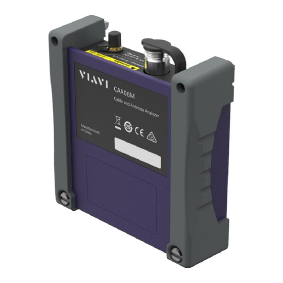
It is essential to have the optimal instrument for properly servicing or installing cell sites. The CAA06M analyzer is the optimal test solution to characterize cell site’s infrastructure due to its ease of use and rich functionality. - Page 16 Introduction to CAA06M Top panel view...
-
Page 17: Features And Capabilities
+12 VDC to +30 VDC with maximum 6 Watts. Features and capabilities The CAA06M Cable and Antenna Analyzer is the optimal portable test solution for installation and maintenance of cellular base stations and cell sites, running with external AC power or battery for the field. -
Page 18: Physical Specifications
Introduction to CAA06M Physical specifications Product Dimension (H x W x D), Weight CAA06M Cable and 130 mm x 138 mm x 41 mm, 0.43 kg for CAA06MA (0.45 kg for CAA06MB) Antenna Analyzer Power supply specifications Power Descriptions DC Input 19 V DC, 8.4 A... -
Page 19: Options
CAA06M Cable and Antenna Analyzer Options This instrument is provided with various options/features that are available to be ordered. See “Appendix information” for more information. A. Ordering... -
Page 21: Getting Started
You need to attach the CAA06M Cable and Antenna Analyzer to your mainframe. 1 Power off your mainframe. 2 Put the upper hooks of CAA06M into the holes (A) and push it tightly to fit in the rear panel (B). 3 Screw the lower part of the module with a flat-head screwdriver. -
Page 22: Glancing At Menus And Icons
Getting Started Glancing at menus and icons There are menus and icons that you need to get familiar with to operate CAA06M Cable and Antenna Analyzer efficiently. Menus on the side bar Items Name Description Tap to view all menus for the selected measurement and mode. Note that the Menu Menus vary based on the selected measurement and mode. -
Page 23: Managing File
CAA06M Cable and Antenna Analyzer Items Name Description Hold Tap to hold spectrum measurement. Tap to save the current measurement from one of the five file types: Result, Save Result as CSV, Setup, Report, or Screen. Load Tap to load the saved measurement result file. -
Page 24: Creating A Report
Getting Started You can save your current screen, result, and setup into the internal memory or your external USB memory drive, USB A or USB B or SD card. To see the storage location, tap the Folder ( ) icon. Make sure to insert a USB memory drive to USB A or B port and insert the SD card to MicroSD port to enable the option. -
Page 25: Using Event Save
CAA06M Cable and Antenna Analyzer 8 Tap the Image Add button to add up to six screenshots and tap the Apply button. Using event save Depending on the measurement mode, you can let the instrument automatically save measurement screen or result that falls outside the defined limit settings or the Fail indicator is on. You can also set to save the first event and hold the measurement or to save all the events continuously. -
Page 26: Using Load
Getting Started 2 Tap the Favorite Title input field and enter the name using the on-screen keyboard. 3 Tap the Create button. Using load You can load your saved screen, result, and setup from the internal memory or your external USB memory drive, USB A or USB B or SD card. -
Page 27: Using Auto Naming File
CAA06M Cable and Antenna Analyzer You can tap the Folder ( ) icon to select the location. The default setting is greyed out and it is only activated when copy and cut is performed. Tap to cut a selected file or folder. -
Page 28: Customizing Auto Naming Template And List
Getting Started Customizing auto naming template and list 1 Follow the steps 1 to 4 above ‘Saving auto naming file’. 2 Tap the Tool ( ) icon to customize the auto naming file and do the following: a Tap Custom, Measurement, or System page you want and tap the items you want to add. b Tap the Add button then tap the Add to List button at the bottom right of the page. -
Page 29: Enabling Software Options
You can enable purchased software options by using the Import Options from USB button. Please call the regional VIAVI Solutions Sales Office for more details about enabling options. They will ask you the serial number of the test instrument for which the upgrade or software option was ordered. -
Page 30: Installing Software Options
You can enable purchased software options by using the Import Options from USB button. Before installing the options, you need to have a USB memory stick including option files provided by VIAVI. 1 Select the System Setting icon, then select System Info. -
Page 31: Performing Calibration
Performing Calibration Introduction This chapter provides instructions on how to perform calibration properly in order to obtain accurate measurement results. Topics discussed in this chapter are as follows: ▪ Understanding calibration ▪ Performing 1-port calibration ▪ Performing 2-port calibration Understanding calibration Calibration of your instrument to the Open, Short, and Load standards is important to get reliable and accurate measurement results. -
Page 32: O-S-L Calibration Using Mechanical Y-Cal Kit
Performing Calibration O-S-L calibration using mechanical Y-Cal kit Procedure 1 Connect an extension cable, if necessary, to the Reflection / RF Out port of the instrument. 2 Tap icon in the right side bar. The on-screen instruction appears to guide you through the mechanical O-S-L calibration. -
Page 33: O-S-L Calibration Using Electronic Ez-Cal Kit
CAA06M Cable and Antenna Analyzer O-S-L calibration using electronic EZ-Cal kit The e-Calibration is an Open-Short-Load calibration using the electronic EZ-Cal kit, which allows you to perform the O-S-L calibration easy and fast with only one connection of the kit to the instrument. - Page 34 Performing Calibration 6 Check the screen to see if the calibration status is now changed to 7 After the electronic calibration has been completed, the EZ-Cal kit changes its status back to Open. 8 Make sure to disconnect the EZ-Cal kit including its USB connection.
-
Page 35: Quick Calibration
CAA06M Cable and Antenna Analyzer Quick calibration The Quick calibration that is available only in the DTF measurement mode is useful when you want to measure the cable length only, without having to perform a full calibration. It's only valid only for a DTF measurement in the single layout. -
Page 36: Thru Calibration
Performing Calibration Below figure illustrates a connection setup for Thru calibration only. Prior to this Thru calibration, you must perform O-S-L calibration as described in the previous pages. Thru calibration Procedure 1 Connect the test cable to the Reflection / RF Out port and RF In port of the instrument. 2 Tap Thru Cal to start calibration. -
Page 37: Reflection Test
Reflection Test Introduction This chapter provides instructions on how to perform Reflection measurements in VSWR or Return Loss. Topics discussed in this chapter are as follows: ▪ Introducing reflection measurements ▪ Preparing for a measurement ▪ Making a measurement Introducing reflection measurement Reflection measurements in VSWR or Return Loss are used to characterize cable and antenna system in order to ensure a cell site's impedance matching and signal reflection characteristics. - Page 38 Reflection Test In telecommunications, return loss is a measure of power reflected from imperfections in an electrical or optical communication link. The ratio (PR / PT), represents the wave power reflected from the imperfection (PR) to that of the incident, or transmitted, wave, (PT). For maximum transmitted power, the return loss should be as small as possible, meaning the ratio PR / PT should be as small as possible.
-
Page 39: Preparing For A Measurement
CAA06M Cable and Antenna Analyzer Preparing for a measurement Selecting measurement mode 1 Tap Single under the Mode & Measure. 2 Double-tap the Reflection VSWR ( ) or Reflection Return Loss ( ) icon as needed. NOTE You can choose two measurement modes from each window in the Horizontal or Vertical tab if you want to view dual measurements displayed on one screen. - Page 40 Reflection Test You can set maximum and minimum values of the Y-scale manually by setting the Top and Bottom amplitudes or restore the instrument's default full scale defined for each measurement mode. You can also optimize the Y-scale automatically so that an entire trace can be displayed on the measurement chart.
-
Page 41: Making A Measurement
CAA06M Cable and Antenna Analyzer suspect interfering signals in the area as it slows down measurement. 4 For users with the Bias Tee installed. To use the Bias Tee, Select On for the Bias Voltage and input a value between 12 and 30 with 1 V step, as you desire. Tap Apply to save the changes. -
Page 42: Analyzing Measurement Results
Reflection Test WARNING Do not attempt to connect the instrument to the antenna when there is a risk of lightning. Electric shock may cause malfunction of or damage to the instrument. 4 Tap Channel Number and input a value using the on-screen keyboard. 5 Tap the Continue button on the right edge to continue. - Page 43 CAA06M Cable and Antenna Analyzer Reflection return loss measurement screen (single layout) Reflection return loss measurement screen (zoom zones)
- Page 44 Reflection Test Reflection VSWR & DTF return loss measurement screen (horizontal layout) Reflection return loss & smith chart measurement screen (vertical layout)
- Page 45 CAA06M Cable and Antenna Analyzer...
-
Page 47: Dtf Testing
DTF Testing Introduction This chapter provides instructions on how to perform DTF (Distance to Fault) measurements in VSWR or Return Loss. Topics discussed in this chapter are as follows: ▪ Introducing DTF measurements ▪ Preparing for a measurement ▪ Making a measurement Introducing DTF measurements While VSWR is an indicator to express the efficiency of the cell site's energy transmission, DTF is a measurement to identify the fault locations in the antenna line system. -
Page 48: Preparing For A Measurement
DTF Testing Preparing for a measurement Selecting measurement mode 1 Tap Single under the Mode & Measure. 2 Double-tap the DTF VSWR ( ) or DTF Return Loss ( ) icon as needed. NOTE You can choose two measurement modes from each window in Horizontal or Vertical tab if you want to view dual measurements displayed on one screen.. - Page 49 CAA06M Cable and Antenna Analyzer 1 Tap the Menu ( ) key on the side bar and tap Frequency. 2 Input the values of Start Frequency, Stop Frequency, Center Frequency, Span Frequency using the on-screen keyboard and tap Apply. 3 To select a band: a Tap the Band List then it displays a list of standard bands stored in the instrument and custom bands created in the JDViewer.
- Page 50 DTF Testing NOTE You can also tap Auto Scale( ) any time you need to view the entire trace on the measurement chart. The instrument automatically optimizes the maximum and minimum values of the Y-scale to display the entire trace. General parameters You can select options for Data Points, Interference Rejection, Windowing, Distance unit and Bias Tee.
- Page 51 CAA06M Cable and Antenna Analyzer 6 For users with the Bias Tee installed. To use the Bias Tee, Select On for the Bias Voltage and input a value between 12 and 30 with 1 V step, as you desire. Tap Apply to save the changes.
-
Page 52: Making A Measurement
DTF Testing Making a measurement Once the O-S-L or Quick calibration is done, the instrument is now ready to make a DTF measurement in VSWR or Return Loss. If you like to not only measure the DTF cable length but also get highly accurate and reliable data, you need to perform a full O-S-L calibration. - Page 53 CAA06M Cable and Antenna Analyzer DTF return loss measurement screen (single layout) DTF return loss measurement screen (Alt DTF Band on)
- Page 54 DTF Testing Reflection VSWR & DTF return loss measurement screen (horizontal layout) DTF VSWR & Smith chart measurement screen (vertical layout)
- Page 55 CAA06M Cable and Antenna Analyzer...
-
Page 57: 1-Port Cable Loss Testing
1-Port Cable Loss Testing Introduction This chapter provides instructions on how to perform 1 Port Cable Loss measurements that are used to quantify signal loss in a cable or other device without connecting both ends of the cable or device to the instrument. -
Page 58: Preparing For Measurement
1-Port Cable Loss Testing Preparing for measurement Selecting measurement mode 1 Tap Single under the Mode & Measure. 2 Double-tap the 1 Port Cable Loss ( ) icon. NOTE You can choose two measurement modes from each window in the Horizontal or Vertical tab if you want to view dual measurements displayed on one screen. - Page 59 CAA06M Cable and Antenna Analyzer 1 Tap the Menu ( ) key on the side bar and tap Frequency. 2 Input the values of Start Frequency, Stop Frequency, Center Frequency, Span Frequency using the on-screen keyboard and tap Apply. 3 To select a band tap the Band List then it displays a list of standard bands stored in the instrument and custom bands created in the JDViewer.
-
Page 60: Making A Measurement
1-Port Cable Loss Testing 2 To set the measurement resolution, select the Data Points option from the choices: 126, 251, 501, 1001 and 2001. NOTE Default setting is 1001. It is recommended that you select high resolution data points only for an instance of measuring wide frequency bands or requiring precise measurement data. -
Page 61: Analyzing Measurement Results
CAA06M Cable and Antenna Analyzer NOTE Do not change the connected port extension cable or frequency settings, or it may cause a measurement error. Analyzing measurement results You can use the Marker, Peak, Trace, Limit, Hold and Auto Scale icons and Zoom Zone function for your analysis of the results. - Page 62 1-Port Cable Loss Testing...
-
Page 63: 1-Port Phase Testing
1-Port Phase Testing Introduction This chapter provides instructions on how to perform 1 Port Phase measurements to tune DUT’s impedance matching and phase match cables. Topics discussed in this chapter are as follows: ▪ Introducing 1-port phase measurements ▪ Preparing for a measurement ▪... -
Page 64: Preparing For A Measurement
1-Port Phase Testing Preparing for a measurement Selecting measurement mode 1 Tap Single under the Mode & Measure. Double-tap the 1 Port Phase ( ) icon. NOTE You can choose two measurement modes from each window in the Horizontal or Vertical tab if you want to view dual measurements displayed on one screen. Setting parameters Frequency You can manually set a frequency band to be measured by entering start and stop frequencies or center... - Page 65 CAA06M Cable and Antenna Analyzer Amplitude You can set maximum and minimum values of the Y-scale manually by setting the Top and Bottom amplitudes or restore the instrument's default full scale defined for each measurement mode. You can also optimize the Y-scale automatically so that an entire trace can be displayed on the measurement chart.
-
Page 66: Making A Measurement
1-Port Phase Testing suspect interfering signals in the area as it slows down measurement. 4 For users with the Bias Tee installed. To use the Bias Tee, Select On for the Bias Voltage and input a value between 12 and 30 with 1 V step, as you desire. Tap Apply to save the changes. NOTE If you have set this Bias Voltage to On, the instrument will supply a DC bias of set level (12 –... -
Page 67: Analyzing Measurement Results
CAA06M Cable and Antenna Analyzer WARNING Do not attempt to connect the instrument to the antenna when there is a risk of lightning. Electric shock may cause malfunction of or damage to the instrument. Analyzing measurement results You can use the Marker, Peak, Trace, Limit, Hold and Auto Scale icons and Zoom Zone function for your analysis of the results. -
Page 68: Cable Delay Testing
Cable Delay Testing Introduction This chapter provides instructions on how to perform Cable Delay measurements. Topics discussed in this chapter are as follows: ▪ Introducing Cable Delay measurements ▪ Preparing for a measurement ▪ Making a measurement Introducing cable delay measurements The Cable Delay mode allows you to measure the cable delay and view it in the time domain. -
Page 69: Preparing For A Measurement
CAA06M Cable and Antenna Analyzer Preparing for a measurement Selecting measurement mode 1 Tap Single under the Mode & Measure. 2 Double-tap the Cable Delay ( ) icon. NOTE You can choose two measurement modes from each window in Horizontal or Vertical tab if you want to view dual measurements displayed on one screen.. - Page 70 Cable Delay Testing is desirable to set the frequency to a value that covers a normal range of the measurement with enough margins. 1 Tap the Menu ( ) key on the side bar and tap Frequency. 2 Input the values of Start Frequency, Stop Frequency, Center Frequency, Span Frequency using the on-screen keyboard and tap Apply.
- Page 71 CAA06M Cable and Antenna Analyzer NOTE You can also tap Auto Scale( ) any time you need to view the entire trace on the measurement chart. The instrument automatically optimizes the maximum and minimum values of the Y-scale to display the entire trace.
-
Page 72: Making A Measurement
Cable Delay Testing set level (12 – 30 V) from the SMA port to an external bias-tee device. Performing calibration Perform the mechanical or electronic O-S-L Calibration by tapping the icon in the right side bar. The instrument displays on-screen instructions for you to follow through. Making a measurement Once the O-S-L or Quick calibration is done, the instrument is now ready to make a cable delay measurement. -
Page 73: Analyzing Measurement Results
CAA06M Cable and Antenna Analyzer lightning. Electric shock may cause malfunction of or damage to the instrument. Analyzing measurement results You can use the Marker, Peak, Trace, Limit, Hold and Auto Scale icons for your analysis of the results. You can also use Quick Save, Save and Load functions. See "Analysis" for details. -
Page 75: Smith Chart Testing
Smith Chart Testing Introduction This chapter provides instructions on how to perform reflection measurements in Smith Chart. Topics discussed in this chapter are as follows: ▪ Introducing Smith chart measurements ▪ Preparing for a measurement ▪ Making a measurement Introducing Smith chart measurements You can view reflection measurements in Smith Chart, which is used to display impedance matching characteristics in the cable and antenna system as well as filter and duplexers devices. -
Page 76: Preparing For A Measurement
Smith Chart Testing Preparing for a measurement Selecting measurement mode 1 Tap Single under the Mode & Measure. Double-tap the Smith Chart ( ) icon. NOTE You can choose two measurement modes from each window in the Horizontal or Vertical tab if you want to view dual measurements displayed on one screen. Setting parameters Frequency You can manually set a frequency band to be measured by entering start and stop frequencies or center... - Page 77 CAA06M Cable and Antenna Analyzer 1 Tap the Menu ( ) key on the side bar and tap Frequency. 2 Input the values of Start Frequency, Stop Frequency, Center Frequency, Span Frequency using the on-screen keyboard and tap Apply. 3 To select a band: a Tap the Band List then it displays a list of standard bands stored in the instrument and custom bands created in the JDViewer.
-
Page 78: Making A Measurement
Smith Chart Testing 4 For users with the Bias Tee installed. To use the Bias Tee, Select On for the Bias Voltage and input a value between 12 and 30 with 1 V step, as you desire. Tap Apply to save the changes. NOTE If you have set this Bias Voltage to On, the instrument will supply a DC bias of set level (12 –... - Page 79 CAA06M Cable and Antenna Analyzer Smith chart measurement screen (single layout) DTF VSWR & Smith chart measurement screen (vertical layout)
-
Page 81: 2-Port Transmission Testing
2-Port Transmission Testing Introduction This chapter provides instructions on how to perform the 2-Port Transmission measurement. It is used to quantify signal gain or loss in a cable or other devices with connecting both ends of the cable or device to the instrument. -
Page 82: Preparing For A Measurement
2-Port Transmission Testing If the power transmitted by the source is PT and the power received by the load is PR, then the insertion loss is given by PR divided by PT. For maximum power transfer the insertion loss should be as small as possible. - Page 83 CAA06M Cable and Antenna Analyzer Frequency You can manually set a frequency band to be measured by entering start and stop frequencies or center and span frequencies. You can also select a frequency band from the band list stored in the instrument. It is desirable to set the frequency to a value that covers a normal range of the measurement with enough margins.
- Page 84 2-Port Transmission Testing maximum and minimum values of the Y-scale to display the entire trace and the limit. General parameters You can select options for Data Points, Interference Rejection, and Bias Tee. 1 Tap the Menu ( ) key on the side bar and tap General. 2 To set the measurement resolution, select the Data Points option from the choices: 126, 251, 501, 1001 and 2001.
-
Page 85: Making A Measurement
CAA06M Cable and Antenna Analyzer Performing calibration Perform the O-S-L-Thru Calibration by tapping the icon in the right side bar. The instrument displays on-screen instructions for you to follow through. Making a measurement Once the O-S-L calibration is done, the instrument is now ready to make a measurement. - Page 86 2-Port Transmission Testing...
-
Page 87: Cw Signal Generating
CW Signal Generating Introduction This chapter provides instructions on how to use the CW Signal Generator function. Topics discussed in this chapter are as follows: ▪ Introducing RF source ▪ Using RF source Introducing RF source If RF CW Source option (CA5000-S006) is installed on your instrument, you can use the RF Source feature to provide different power levels as like using a CW signal generator. -
Page 88: Using Rf Source
CW Signal Generating Using RF source Selecting measurement mode 1 Tap Single under the Mode & Measure. 2 Double-tap the RF Source ( ) icon. NOTE You can choose two measurement modes from each window in the Horizontal or Vertical tab if you want to view dual measurements displayed on one screen. Turing on RF source You can turn on the RF Source feature to generate a CW signal of different output power levels. -
Page 89: Caa Check
Creating a report Introducing CAA Check measurement CAA Check is a standard feature that you can use on CAA06M Cable and Antenna Analyzer. It enables you to create and run task systematically as defined in the testing sequence with minimal manual work and intervention. -
Page 90: Preparing For A Measurement
CAA Check Preparing for a measurement Selecting measurement mode 1 Tap Single under the Mode. 2 Double-tap the CAA Check ( ) icon. Once tapped, the CAA Check landing page appears. NOTE CAA Check is only available in Single tab and viewing dual measurement display is not available. -
Page 91: Setting A Test
CAA06M Cable and Antenna Analyzer Tap the Add icon to add a task. You can add up to Move Tap to move the added task down. down Move up Tap to move the added task up. Tap to undo copy, cut, or select. The default setting is greyed out and it is only Edit activated when copy and cut is performed. - Page 92 CAA Check 1 Tap Cable Name and select a cable from the cable list pop-up window. The instrument automatically changes the Propagation Velocity and Cable Loss values correspondent to the selected cable's propagation velocity and cable loss. Default setting is HFC-12D (1/2"). 2 Tap the Propagation Velocity and enter a value using the on-screen keyboard.
-
Page 93: Setting Prompt
CAA06M Cable and Antenna Analyzer Input the values of Top and Bottom amplitudes using the on-screen keyboard. 2 Tap the Apply. The entered values become the maximum and minimum values for the Y-scale. Limit The Limit Line is a straight horizontal line that you can enable to analyze your measurement results. -
Page 94: Saving Results From A Task
CAA Check ▪ 4 Peaks: Searches for four peaks with four Normal markers from M1 to M4 regardless of the previous marker setting ▪ Valley: Searches for the lowest peak (valley) on the trace ▪ 4 Valleys: Searches for four valleys with four Normal markers from M1 to M4 regardless of the previous marker setting 3 Tap to select Scale from the three options. -
Page 95: Loading A Profile
CAA06M Cable and Antenna Analyzer Loading a profile You can directly create a new profile or load your saved profile before running a test. If you have any saved profiles in your instrument, you can load one by tapping the Get Started button in the Load Profile pane on the left. -
Page 96: Running A Test
CAA Check Items Name Description Tap the Folder ( ) icon to open the files or folders you want to select. Tap to Select select files or folders. Tap to create a new folder. Once tapped, the on-screen keyboard pops up and enter any folder name that you want to create. - Page 97 CAA06M Cable and Antenna Analyzer NOTE If you move to Home, Test Setting, or Save Profile in the middle of running a test, a pop-up message appears. Tap the No button to move without saving a report or tap the Yes button to move to Report and save it.
-
Page 98: Creating A Report
CAA Check While running a test, you will see the Settings, Status, Retest, and Result icons next to the added task. See the table below for definition. Icon Name Description Tap the Settings icon to see the summary of the test settings. A pop-up Settings Settings window appears with its parameters previously set. - Page 99 CAA06M Cable and Antenna Analyzer ▪ Customer: Customer's name ▪ Technician ID: Tester's ID in the cell site ▪ Work Order ID: Work order identification ▪ Test Location: Summary of the site where the test was proceeded ▪ Radio: Radio setting ▪...
-
Page 101: Analysis
Analysis Introduction This chapter provides instructions to analyze measurement results. Topics discussed in this chapter are as follows: ▪ Using zoom zones ▪ Using alternate DTF band ▪ Using markers ▪ Searching for peak or valley ▪ Displaying traces ▪ Setting test limits ▪... -
Page 102: Using Alternate Dtf Band
Analysis 1 The top half of the screen shows the chart with the trace for the full O-S-L calibration band while the bottom half of the screen displays zoom zones that you have enabled in the Zoom setting. 2 Individual zoom zones on the screen are independent from one other. Function keys correspond only with the selected zone, which is called as the "active"... -
Page 103: Using Markers
CAA06M Cable and Antenna Analyzer NOTE Minimum value for the Alternate Span is 2% of what you have set for the Span in the Frequency/Distance tab. 3 Input the Start Distance and Stop Distance. 4 The text "Alt DTF Band: On" appears at the top left corner of the DTF measurement plot. - Page 104 Analysis 1 Tap the marker menu ( ) on the side bar. 2 Tap one of the six marker screen keys (M1 to M6), which you like to position on the trace. The active marker’s readout is displayed on the screen as shown in below screen capture. 3 To change the active marker type, tap the marker number screen key and then select the marker type option from the following choices: ▪...
-
Page 105: Moving, Hiding, And Clearing A Marker
CAA06M Cable and Antenna Analyzer Moving, hiding, and clearing a marker 1 To move the active marker, do one of the following: a Tap a new position on the trace. The active marker jumps to the new position on the active trace. -
Page 106: Searching For Peak Or Valley
Analysis Searching for peak or valley You can easily find a peaks or valley on the trace, 4 peaks or valleys, and peak or valley between two markers. When a zoom zone is selected, you will have a different set of menus. Finding a peak or valley 1 Tap the peak search menu, ( ) on the side bar. -
Page 107: Performing Trace Math
CAA06M Cable and Antenna Analyzer 1 Tap Trace in the Menu ( ) key on the side bar. By default, the instrument sets the first trace, Trace 1 on and displays "T1 W ". 2 Tap one of the six traces (Trace 1 to Trace 6), which you want to set, and tap to Trace View On. -
Page 108: Loading A Saved Trace
Analysis Trace math is not available in the DTF and Smith Chart modes. 3 To turn off the trace math function, tap Trace Math Type to Off. Loading a saved trace You can load a saved trace whenever you need. Unlike the trace overlay, the display layout mode changes to the single display and measurement settings such as measurement mode and X and Y scales are restored as saved. -
Page 109: Setting Test Limits
CAA06M Cable and Antenna Analyzer Setting test limits You can define test limits for automatic Pass/Fail and Warning indication and display a limit line with single or multiple segments or a limit window. It makes it easy to verify that a measurement exceeds defined thresholds with alarming option, which sounds if any portion of the trace falls outside the limit settings. - Page 110 Analysis 4 Tap Multi Segment Line and Upper/Lower to select Upper or Lower as desired. 5 To set the number of segments for the MSL, tap Segments. Enter a value between 1 and 50 using on-screen keyboard. 6 Tap Auto for the instrument to automatically set values for the MSL segment(s). 7 Tap Display and select On to display the MSL line.
-
Page 111: Setting A Limit Window
CAA06M Cable and Antenna Analyzer MSL line with red point Setting a limit window 1 Tap Limit in the Menu ( ) key on the side bar. 2 Select the Alarm Sound option between On and Off. If you select On, the instrument goes off an alarm when a result falls outside of defined limits. -
Page 112: Holding A Measurement
Analysis e Optional: To save the limit settings, tap Save ( Limit window Holding a measurement You can put a measurement on hold and resume sweeping as needed. 1 Tap Hold ( ) icon on the side bar. Sweeping is paused. 2 To resume the measurement, tap Hold ( ) icon again. -
Page 113: Appendix
Appendix A. Ordering information The Warranty Period for VIAVI Solutions Accessories shall apply to all the standard and optional accessories listed below. The warranty period varies by product and is generally 3 years for CAA Modules and 1 year for other accessories unless otherwise specified. - Page 114 Appendix JD78050509 Y-Calibration Kit, Type-N(m), DC to 6 GHz, 50 ohm JD78050510 Y-Calibration Kit, DIN(m), DC to 6 GHz, 50 ohm JD70050509 EZ-Cal kit Type-N(m), DC to 6 GHz, 50 ohm JD78050507 Dual port Type-N 6 GHz calibration kit JD78050508 Dual port DIN 6 GHz calibration kit G700050530 RF cable DC to 8 GHz Type-N(m) to Type-N(m), 1.0 m...
-
Page 115: Rohs Information
CAA06M Cable and Antenna Analyzer G700050577 Adapter Type-N(f) to DIN(f), DC to 7.5 GHz, 50 ohm G700050578 Adapter Type-N(f) to DIN(m), DC to 7.5 GHz, 50 ohm G700050579 Adapter DIN(f) to DIN(f), DC to 7.5 GHz, 50 ohm G700050580 Adapter Type-N(m) to Type-N(m), DC to 11 GHz 50 ohm G700050581 Adapter N(m) to QMA(f), DC to 6.0 GHz, 50 ohm... - Page 116 Appendix...
- Page 117 Doc No. 22134163 Rev 7.00, December 2022 English VIAVI Solutions North America (Toll Free) 1-844-GO-VIAVI / 1-844-468-4284 Latin America +52 55 5543 6644 EMEA +49 7121 862273 APAC +1 512 201 6534 All other regions www.viavisolutions/contacts Email TAC@viavisolutions.com...
Need help?
Do you have a question about the CAA06M and is the answer not in the manual?
Questions and answers