Table of Contents
Advertisement
Quick Links
Advertisement
Table of Contents

Related Manuals for Viavi CPRIAdvisor CAP-100


Summary of Contents for Viavi CPRIAdvisor CAP-100
- Page 1 CPRIAdvisor Version 1.0 Installation Guide...
- Page 2 CPRIAdvisor Version 1.0 Installation Guide Viavi Solutions 1-844-GO-VIAVI www.viavisolutions.com...
- Page 3 Copyright/Trademarks © Copyright 2016 Viavi Solutions Inc. All rights reserved. No part of this guide may be reproduced or transmitted, electronically or otherwise, without written permission of the publisher. Viavi Solutions, the Viavi logo, CellAdvisor, StrataSync, and EZ-Cal are trademarks of Viavi Solutions Inc. (“Viavi”). All trademarks and registered trademarks are the property of their respective companies.
- Page 4 NRTL compliance This product was tested according to UL 61010-1:2012 and CAN/CSA C22.2 No. 61010-1-12. Conformity with these requirements is based upon compliance with the standard IEC 61010-1. A copy of the Declaration of Conformity is provided upon your request. EMC directive compliance This product was tested and conforms to the EMC Directive, 2014/30/EU and its amending directives for electromagnetic compatibility.
-
Page 5: Table Of Contents
Safety and compliance information ............................7 Safety consideration ..............................7 Conventions ..................................7 Technical assistance ................................9 Chapter 2 Introduction to CPRIAdvisor CAP-100 and CAE-100 ..........10 CPRIAdvisor CAP-100 and CAE-100 ..........................11 Features ..................................... 11 Specifications ..................................11 General specifications ..............................11 Chapter 3 Installing CPRIAdvisor CAP-100 and CAE-100 ............ -
Page 6: Chapter 1 About This Guide
Chapter 1 About This Guide Chapter 1 About This Guide Topics discussed in this chapter include the following: Purpose and scope ....................... 7 Assumptions ........................7 Safety and compliance information ................7 Conventions ........................7 Technical assistance ..................... -
Page 7: Purpose And Scope
Chapter 1 About This Guide Purpose and scope The purpose of this manual is to help you successfully install the CPRIAdvisor CAP-100 and CAE- 100. It includes instructions that describe how to install, set up, configure, and use the CPRIAdvisor CAP-100 and CAE-100 easily. - Page 8 Chapter 1 About This Guide Table 1 Text formatting and other typographical conventions Item Text formatting/symbols used Example(s) Turn the POWER switch on. Buttons or switches that Bold, all caps, default font you press or flip on a physical device. Tap the Limit Line screen key.
-
Page 9: Technical Assistance
When applied to software actions, indicates a situation that, if not avoided, could result in loss of data or a disruption of software operation. Technical assistance If you require technical assistance, call 1-844-GO-VIAVI or send an email to TAC@viavisolutions.com. For the latest TAC information, go to http://www.viavisolutions.com/en/services-and-support/support/technical-assistance. -
Page 10: Chapter 2 Introduction To Cpriadvisor Cap-100 And Cae-100
Chapter 2 Introduction to CPRIAdvisor CAP-100 and CAE-100 This chapter provides a general description of the CPRIAdvisor CAP-100 and CAE-100. Topics discussed in this chapter include the following: CPRIAdvisor CAP-100 and CAE-100 ................11 Features ..........................11 ... -
Page 11: Cpriadvisor Cap-100 And Cae-100
(CAP-100), Expansion unit (CAE-100), and a remote controlling and monitoring program (CAM-100). Viavi’s CAP-100 is a key solution that has 16 optical ports to receive 16 optical inputs to perform RFoCPRI spectrum monitoring. The CAP-100 can store thousands of CPRI profiles and RRH information and can monitor all uplinks and detect RSSI or PIM alarm. - Page 12 Chapter 2 Introduction to CPRIAdvisor CAP-100 and CAE-100 Weight 3.1 kg Optical input power range -4 dBm to 24 dBm CPRI link rate Up to 4.9 Gbps (Upgradable to 9.8G) IO interface Optical input 16x LC ports USB host port...
- Page 13 Chapter 2 Introduction to CPRIAdvisor CAP-100 and CAE-100 Input voltage range +8 to +15V Power Supply Power consumption Operating 0°C to 40°C (operating, temperature range) Environment Storage -20°C to 60°C Humidity 5% to 95% without condensing Vibration MIL-PRF-28800F Class 3...
-
Page 14: Chapter 3 Installing Cpriadvisor Cap-100 And Cae-100
Chapter 3 Installing CPRIAdvisor CAP-100 and CAE-100 This chapter describes how to get started with the CPRIAdvisor CAP-100 and CAE-100. Topics discussed in this chapter are as follows: Unpacking the CPRIAdvisor CAP-100 and CAE-100 ..........15 Exploring the CPRIAdvisor CAP-100 ................15 ... -
Page 15: Unpacking The Cpriadvisor Cap-100 And Cae-100
Viavi's authorized sales and service office. A basic set of the CPRIAdvisor CAP-100 should include the following items in the package. Table 6 Items included... -
Page 16: Front View
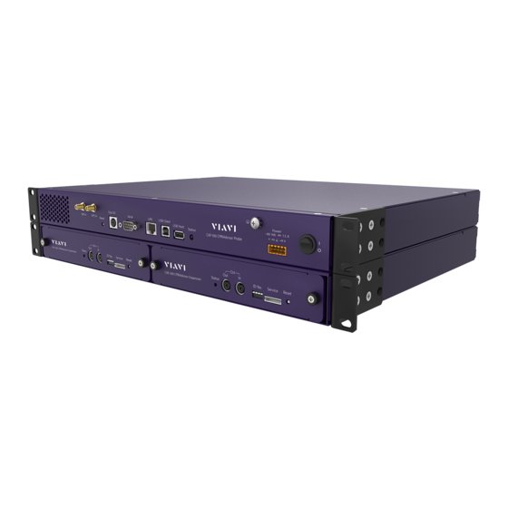
Chapter 3 Installing CPRIAdvisor CAP-100 and CAE-100 Front view Figure 1 CPRIAdvisor CAP-100 front view Description Reset Expansion control Serial port LAN port USB client port USB host port LED status light Grounding connection -48 VDC port Power switch Reset You can use this key to reset your CAP-100. -
Page 17: Rear View
Chapter 3 Installing CPRIAdvisor CAP-100 and CAE-100 LED status light This LED status light shows the operation status of the CAP-100. Once the CAP-100’s booting is completed, it changes from red to illuminating green. NOTE The green LED is illuminated when there is a valid communication connection. -
Page 18: Exploring The Cpriadvisor Cae-100
Chapter 3 Installing CPRIAdvisor CAP-100 and CAE-100 Exploring the CPRIAdvisor CAE-100 Front view Figure 3 CPRIAdvisor CAE-100 front view (2 CAE-100) Description LED status light Control out port Control in port ID number Service port Reset Grounding connection Control out port You can use this port to connect the CAE-100 via cascading. -
Page 19: Rear View
You can use this port to connect the optical LC cable. You can connect 36xLC optical ports per each CAE-100. Installing the CPRIAdvisor CAP-100 After inspecting your shipment, follow the procedure below to install the CPRIAdvisor CAP-100. Procedure To install with a 19-inch rack: Using a Phillips-head screwdriver, install the brackets with screws provided. - Page 20 Chapter 3 Installing CPRIAdvisor CAP-100 and CAE-100 To install with a 23-inch rack: Using a Phillips-head screwdriver, install the brackets with screws provided. The bracket size is longer than the one in the 19-inch rack. Mount the CAP-100 to both ends of a 23-inch rack.
- Page 21 Chapter 3 Installing CPRIAdvisor CAP-100 and CAE-100 Connect the two MPO connectors on the rear of the MPO patch panel. Connect the 16 LC connectors to each 16 optical input ports on the rear of the CAP-100. Connect a LAN cable and a -48 VDC input power cable to the CAP-100. Make sure you connect input (–) and return (+) correctly.
-
Page 22: Installing The Cpriadvisor Cae-100
Chapter 3 Installing CPRIAdvisor CAP-100 and CAE-100 NOTE The number of optical cables to be connected varies based on your installation environment. Turn the POWER switch on. Check whether the status LED changes from red to green and wait until the green LED illuminated. - Page 23 Chapter 3 Installing CPRIAdvisor CAP-100 and CAE-100 Mount the CAE-100 to a 19-inch shelf inserted under the CAP-100. NOTE The cabinet model RBS6101 and RBS6120 require mid-mount brackets which are inversely attached to the CAE-100 due to space limit. To install with a 23-inch rack: Using a Phillips-head screwdriver, install the brackets with screws provided.
- Page 24 Chapter 3 Installing CPRIAdvisor CAP-100 and CAE-100 Connect the three 12xMPO (12pin MPO) connectors on the rear of MPO adapter of the MPO Adapter panel. Connect the 36xLC connectors on the other side to 36 optical input ports aligned with the number in the label on the rear of the CAE-100.
-
Page 25: Grounding The Cpriadvisor Cap-100
Grounding the CPRIAdvisor CAP-100 The CPRIAdvisor CAP-100 must be grounded to the building’s earth ground system. It is suitable for installation as part of the Common Network Bonding (CBN). The symbol ( ) appears on the CPRIAdvisor system shelf to indicate a ground conductor terminal. -
Page 26: Grounding The Cpriadvisor Cae-100
Chapter 3 Installing CPRIAdvisor CAP-100 and CAE-100 Grounding the CPRIAdvisor CAE-100 The CPRIAdvisor CAE-100 must be grounded to the building’s earth ground system. It is suitable for installation as part of the Common Network Bonding (CBN). The symbol ( ) appears on the CPRIAdvisor system shelf to indicate a ground conductor terminal. - Page 27 Chapter 3 Installing CPRIAdvisor CAP-100 and CAE-100 to none. In Windows Device Manager, look for the serial port assigned correctly to your PC and note the COM number (for example, it may appear as COM1). If all setting values above are correctly input, the following on-screen prompt appears.
- Page 28 Chapter 3 Installing CPRIAdvisor CAP-100 and CAE-100 To configure Ethernet via DHCP: Download a Tera Term. Install it on your computer. Run the terminal emulator program. Set the proper COM port from the terminal emulation program configuration. Set the Baud Rate to 115200, Data to 8bit, Parity to none, Stop to 1bit, and Flow Control to none.
- Page 29 Chapter 3 Installing CPRIAdvisor CAP-100 and CAE-100 You need to select Ethernet Configuration. Type 3 in Select number. If you want to enable automatic IP addressing, type d between the three choices: s, d or The following two on-screen prompts appear.
-
Page 30: Setting Date And Time
Chapter 3 Installing CPRIAdvisor CAP-100 and CAE-100 NOTE Automatic IP address detection via DHCP occurs only three times. If it fails to find the IP address within three times, you need to exit by pressing Ctrl+c. As a follow-up measure, check if your LAN cable is properly inserted or DHCP server operates well. - Page 31 Chapter 3 Installing CPRIAdvisor CAP-100 and CAE-100 Select a proper location based on your time zone. Select a country that matches with your time zone (For example, 23 if you are in South Korea) If the time zone appeared in the on-screen prompt is correct, type 1.
-
Page 32: Manual Setting
Chapter 3 Installing CPRIAdvisor CAP-100 and CAE-100 The date and time are automatically set based on your selected time zone. Manual setting You can manually set date and time. Procedure On the on-screen prompt of the terminal emulator program, type 4. -
Page 33: Upgrading Firmware
Ctrl+c and set your time and date again. Upgrading firmware It is recommended that you maintain your CAP-100 up-to-date with its latest firmware to achieve the optimal performance. Visit Viavi’s Software Downloads and Updates at http://www.viavisolutions.com/en/services-and-support/support/software-downloads-and- updates#Group-C to check the latest version for your CAP-100 and download it if any newer version... - Page 34 Chapter 3 Installing CPRIAdvisor CAP-100 and CAE-100 Upgrading from terminal emulation program Procedure Connect your PC with the CAP-100 using a serial cable. Run the terminal emulation program such as puTTy and Tera Term. Set the proper COM port from the terminal emulation program configuration.
-
Page 35: Chapter 4 Configuring Cap-100 Via Cam-100
Configuring CAP-100 via CAM-100 Chapter 4 This chapter provides instructions on how to configure CAP-100 properly to check and obtain accurate monitoring results. Topics discussed in this chapter are as follows: Installing the CAM-100 ....................36 Connecting CAP-100 via CAM-100 ................36 ... -
Page 36: Installing The Cam-100
Chapter 4 Configuring CAP-100 Installing the CAM-100 If the IP is assigned to CAP-100 via the terminal emulator program, you need to install the CPRIAdvisor Manager(CAM-100) to set relevant values to configure CAP-100. Only after completing the setup properly, you can view accurate monitoring results via CAM-100. Procedure Install the CAM-100 saved in the USB drive provided on your computer. -
Page 37: Setting Up Cap-100 Via Cam-100
Procedure Click button on the Probe Connection Management pane. Insert the assigned IP address in a pop-up window. Click button at the bottom of the Probe Connection Management pane. Once connected, the Probe appears as highlighted in purple. NOTE If you failed to connect to the Probe, make sure to check your LAN cable is properly connected to Probe and PC. - Page 38 Chapter 4 Configuring CAP-100 pane. Select Probe Configurator from the drop-down list at the bottom of the Probe Information Management pane. Click Note button at the bottom of the Probe Information Management pane. Right-click and select Probe Initialization from the three choices to configure your Probe.
- Page 39 If you click the Apply button, the Probe initialization is completed. To Configure Probe with Expansion: Select Expansion from the drop-down list of Physical Port 01 for example. All Physical Ports need to be set to None. CPRIAdvisor Installation Guide...
- Page 40 Chapter 4 Configuring CAP-100 Click the Expansion icon, and select the number of profiles you want to set from the Profiles of All Ports drop-down list in the Expansion information initialization window (for example, 4). NOTE If you want to check information of all ports or all Expansions, you can select All Ports or All Expansions from the drop-down list.
-
Page 41: Managing Your Cap-100 Information
Managing your CAP-100 Information Procedure After completing the Probe initialization, click the Probe icon, on the Probe Information Management pane. Assign Probe ID in Hardware ID section and complete Location Information fields below. After completing each field with a proper value, press the Enter key on your keyboard. Select a value of IP version from the following choices: IPv4, IPv6, and IPv46. - Page 42 Chapter 4 Configuring CAP-100 NOTE You need to input an accurate value based on RRH setup information. Select a value of NEM (Network Equipment Manufacturer) from the following choices: None,Ericsson, Alcatel-Lucent, Samsung, Huawei,Nokia and ZTE. A default value is None. Click + button in on the Probe Information Management pane.
- Page 43 In Carrier Information Section, do the following steps Click the down arrow for Link direction, and select the option between uplink or downlink. The channel and frequency vary based on the link direction you selected. Click the icon next to the channel standard. ...
-
Page 44: Checking Your Setup
Chapter 4 Configuring CAP-100 uplink or 8 to 20 for downlink. A default value is 12. Click the down arrow for Stuffing bit, and select the option between 0 to 20. A default value is 3. Check or uncheck for the Aggregation. ... - Page 45 Click button at the bottom of the Probe Information Management pane. Click button at the bottom of the Probe Connection Management pane. Once connected, the Probe appears with a check box in front of the Probe icon. Expand the tree structure and check the profiles you have configured. Click button to start the monitoring for the profiles you checked.
- Page 46 Chapter 4 Configuring CAP-100 NOTE You need to check the spectrum chart is properly displayed based on your setting values. There should be no optical power alarm, LOS, and LOF alarms. NOTE You can move the chart on the screen by moving your mouse cursor. You can also align the charts side by side above by clicking Window menu bar and selecting Alignment from the options.
- Page 47 Document No. 22121022 Rev. 1.0, May 2017 English Viavi Solutions North America: 1.844.GO VIAVI / 1.844.468.4284 Latin America: +52 55 5543 6644 EMEA: +49 7121 862273 APAC: +1 512 201 6534 All Other Regions: viavisolutions.com/contacts...
Need help?
Do you have a question about the CPRIAdvisor CAP-100 and is the answer not in the manual?
Questions and answers