
Related Manuals for Viavi MPOL*-85P


Summary of Contents for Viavi MPOL*-85P
- Page 1 MPOLx-85 / MPOLx-85P MPO Light Source/ MPO Power Meter User’s Guide BN 2325/98.21 2017.03 English...
- Page 2 430 N. McCarthy Blvd. • Milpitas, CA 95035 USA Copyright © Copyright 2016 Viavi Solutions Inc. All rights reserved. Viavi and the Viavi logo are trademarks of Viavi Solutions Inc. All other trademarks and registered trademarks are the properties of their respective owners.
-
Page 3: Table Of Contents
ONTENTS ONTENTS ....... . 5 NTRODUCTION MPOLx-85 / MPOLx-85P MPO Test Sets....5 MPOLS-85 Light Sources . - Page 4 ONTENTS PCM & PROBE O ..... 45 PERATION General information ....... . 45 The build in Patch Cord Microscope (PCM) .
-
Page 5: Introduction
NTRODUCTION MPOL -85 / MPOL -85P MPO T NTRODUCTION MPOLx-85 / MPOLx-85P MPO Test Sets The SmartClass™ Fiber MPOLx-85 / MPOLx-85P test sets consist of two pairs of test units: • MPOLS-85 / MPOLP-85 The MPOLS-85 / MPOLP-85 test set consists of a high- performance, easy-to-use MPO light source and a MPO power meter for measuring up to 12 fiber simultaneously. -
Page 6: Mpols-85 Light Sources
NTRODUCTION MPOLS-85 L IGHT OURCES MPOLS-85 Light Sources The SmartClass™ Fiber MPOLS-85 light sources are professional, versatile, compact handheld instruments designed for qualification and certification of fiber optic networks. Carefully chosen combinations of available wavelengths make SmartClass™ Fiber MPOLS-85 light sources the optimum choice for link loss testing and characterization of long-haul, metro, and access telecommunication networks, as well as for data center and local area network testing. -
Page 7: Operating Manual Update
If the operating instructions about features supported by your instrument are missing, please visit the Viavi web site to check if additional information is available. To download the latest user manual: Visit the Viavi web site at http://updatemyunit.net. -
Page 8: Symbols Used In This Operating Manual
NTRODUCTION YMBOLS USED IN THIS OPERATING MANUAL Symbols used in this operating manual Various elements are used in this operating manual to draw attention to special meanings or important points in the text. Symbols and terms used in warnings The following warnings, symbols, and terms are used in this document in compliance with the American National Standard ANSI Z535.6-2011: NOTICE... - Page 9 NTRODUCTION YMBOLS USED IN THIS OPERATING MANUAL Warning format All warnings have the following format: WARNING Type and source of danger Consequences of ignoring the warning. Action needed to avoid danger. The following character formats are used in this operating manual: Requirement This requirement must be met first;...
-
Page 10: Safety Information
AFETY NFORMATION ARNING SYMBOLS ON THE UNIT AFETY NFORMATION Warning symbols on the unit Warning symbols indicating a potential hazard In all cases where the unit is labeled with a warning symbol, the operating manual must be consulted to learn more about the nature of the potential hazard and any action that must be taken. -
Page 11: Laser Safety
AFETY NFORMATION ASER SAFETY Laser safety WARNING Dangerous laser radiation Laser radiation can cause irreparable damage to eyes and skin. This device is a Class 1 laser product according to DIN EN 60825-1:2007. Always be aware of the hazard level of the instrument to be connected. -
Page 12: Ventilation
AFETY NFORMATION ENTILATION Ventilation NOTICE Insufficient ventilation Insufficient ventilation can damage the instrument or adversely affect its function and safety. Ensure adequate ventilation when operating the instrument. PS4 Universal AC/DC Power Supply Safety class The PS4 Universal AC/DC Power Supply unit has a protective isolation that conforms with IEC 60950. - Page 13 AFETY NFORMATION PS4 U AC/DC P NIVERSAL OWER UPPLY NOTICE Condensation Operation in the presence of condensation can damage the PS4 Universal AC/DC Power Supply or adversely affect its function and safety. Do not operate the PS4 Universal AC/DC Power Supply if condensation has formed.
-
Page 14: Getting Started
This is particularly likely if the packaging is visibly damaged. If there is damage, do not attempt to operate the instrument. Doing so can cause further damage. In case of damage, please contact your local Viavi sales company. Addresses can be found at www.viavisolutions.com. Recovery following storage/shipping Condensation can occur if an instrument that is stored or shipped at a low temperature is brought into a warm room. -
Page 15: Instrument Overview
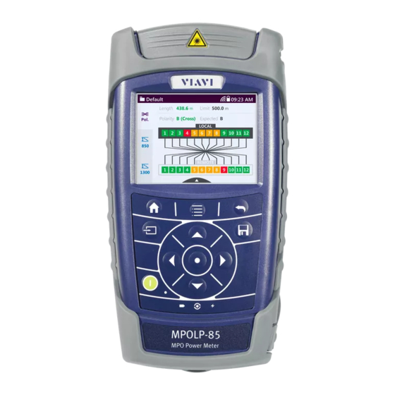
ETTING TARTED NPACKING THE INSTRUMENT Instrument overview Fig. 1 Front view MPOLS-85P (left) and MPOLS-85 Patch cord microscope (PCM) with FMA adapter PCM controls: focus control, automated Pass/Fail analysis, magnification control Connector interface Test head cover (green for APC- and gray for PC connectors) 3.5 inch touchscreen Key pad (operator control panel) Battery compartment and stand (on rear of instrument) -
Page 16: Connector Panel
ETTING TARTED NPACKING THE INSTRUMENT Connector panel Fig. 2 Connector panel MPOLP-85P (top) and MPOLS-85 Patch cord microscope Optical connector: • MPOLP-85, MPOLP-85P: single-mode = APC, multi-mode = PC • MPOLS-85, MPOLS-85P: single-mode = APC Fig. 3 External power supply connector and communication interfaces Ethernet port (RJ-45) External power supply connector USB 2.0 host port (Type A) -
Page 17: Power Supply
ETTING TARTED NPACKING THE INSTRUMENT Power supply The following power sources can be used to operate the MPOLx-85 / MPOLx-85P: • Eight 1.5 V dry batteries (Mignon AA size, alkaline type recommended) • Eight 1.2 V NiMH rechargeable batteries (Mignon AA size, no internal charge) •... - Page 18 ETTING TARTED NPACKING THE INSTRUMENT The battery compartment is on the back of the instrument. Press down the latch to release and to open the lid of the battery compartment. Insert new batteries or remove the used batteries and replace them with fresh ones.
-
Page 19: Environmental Protection
You will often be able to return used batteries to the place where you purchase new ones. Any dry or rechargeable batteries that you purchased from Viavi can be returned to one of our Service Centers for disposal. MPOLx-85 / MPOLx-85P... - Page 20 ETTING TARTED NPACKING THE INSTRUMENT Operation with AC power NOTICE: Only the PS4 Universal AC/DC Power Supply may be used to operate the MPOLS-85 with AC power. To fit the AC line plug adapter: Select the appropriate AC line plug adapter. Slide the AC line plug adapter into the slot.
- Page 21 ETTING TARTED NPACKING THE INSTRUMENT To operate the MPOLS-85 with AC power: Connect the PS4 DC power cord to the MPOLS-85 external power supply connector. (The connector is under the cover on the right side.) Plug the PS4 into the AC line socket. The MPOLS-85 switches on automatically when powered by the PS4.
-
Page 22: Basic Operation
ASIC PERATION WITCHING THE INSTRUMENT ON ASIC PERATION Switching the instrument on/off To switch the instrument on: Press the [E] key to switch on the instrument. To switch the instrument off: Press the [E] key to shift the instrument into hibernate mode. –... -
Page 23: Menus And Display Elements
ASIC PERATION ENUS AND DISPLAY ELEMENTS Menus and display elements Home screen Fig. 7 Home screen Menu See page Dashboard In this menu you can select an operation mode. Management In this menu you can: • manage projects • define a test profile •... - Page 24 ASIC PERATION ENUS AND DISPLAY ELEMENTS Elements in the top bar Project title Indicates the titel of the active project System Settings Shows the selected submenu in the Systems Settings menu. WIFI Indicates an active Wifi connection. External power supply The MPOLS-85 is powered by the external AC adapter when this symbol is shown.
-
Page 25: Navigating In The Menus
ASIC PERATION AVIGATING IN THE MENUS Navigating in the menus Press the [C] key to open the home screen. Depending in the active project type the Projects tab shows the available operation modes or the active Workflow project. Press the [A] key to open the context-sensitive menu. Depending on which application is in the foreground, a different menu opens. -
Page 26: Changing System Settings
ASIC PERATION HANGING YSTEM ETTINGS Changing System Settings In the Settings menu you can change instrument settings, get information and help about the instrument, or update the firmware. To open the Settings menu: The home screen is displayed. Select the tab. -
Page 27: Selecting A Language
ASIC PERATION HANGING YSTEM ETTINGS Configuring the WIFI connection In the menu tap the [WIFI] button. Press the [A] key and tap the desired setting. Configuring the Bluetooth connection In the menu tap the [BLUETOOTH] button. Press the [A] key and tap the desired setting. Adjusting the display brightness In the menu tap the... - Page 28 ASIC PERATION HANGING YSTEM ETTINGS Tap the language you want to select. – or – Press the arrow keys to highlight the language you want to select and to confirm press the center key within the arrow keys. Setting date & time In the menu tap the [More]...
-
Page 29: Updating The Firmware
The latest version of the firmware can be downloaded from the Internet. To find the latest firmware version: Visit the Viavi web site at http://updatemyunit.net. Select your model from the product line. Open the download area and download the latest firmware. - Page 30 ASIC PERATION HANGING YSTEM ETTINGS Plug the USB flash drive into one of the instrument USB ports. To start the firmware update procedure, press the center key within the arrow keys. If the update procedure is terminated, the instrument turns off automatically.
-
Page 31: Managing Projects
ANAGING ROJECTS EATING A NEW PROJECT ANAGING ROJECTS A project is like a folder where you collect you data of a test. At least one project is defined as factory default and set to active. Thus, you do not need to create you own projects but this will help you to organize your results. -
Page 32: Editing A Test Setup
ANAGING ROJECTS DITING A TEST SETUP Editing a test setup You are in the [Management] [PROJECTS] menu. Select a project by tapping it once. – or – Use the arrow keys to highlight a project and press the center button. Edit the available fields. -
Page 33: Performing Aloss/Length Test
LOSS/LENGTH T ERFORMING A ENERAL INFORMATION LOSS/LENGTH T ERFORMING A General information LOSS/LENGTH mode is used to measure loss, length, and polarity of up to 12 fibers simultaneously. Depending on your specific needs a great variety of test types and settings are avialable: How to perform a LOSS/LENGTH test A LOSS/LENGTH test consists of several steps to achieve reliable... - Page 34 LOSS/LENGTH T ERFORMING A ENERAL INFORMATION Important laser warnings WARNING Dangerous laser radiation Laser radiation can cause irreparable damage to eyes and skin. This device is a Class 1 laser product according to DIN EN 60825-1:2007. Always be aware of the hazard level of the instrument to be connected.
-
Page 35: Setting Length Unit And Tone
LOSS/LENGTH T ERFORMING A ETTING LENGTH UNIT AND TONE Setting length unit and tone Length unit and tone settings are not setup specific. To change the length unit: The instrument is in LOSS/LENGTH mode. Press the [A] key. Tap the [More] button. - Page 36 LOSS/LENGTH T ERFORMING A EFINING A TEST CONFIGURATION Ceating a new test configuration The instrument is in LOSS/LENGTH mode. Press the [A] key. Tap the [TEST SETUP] button. The available test configurations are displayed. Select a existing configuration if you want to copy its settings to the new configuration.
- Page 37 LOSS/LENGTH T ERFORMING A EFINING A TEST CONFIGURATION Fiber Type Tap a fiber type to select it: – multi mode – single mode Test Reference Method Tap a reference method to select it: – 1-chord – 3-chord Cable & Connector Settings Open a drop down lists and tap the wanted entry: –...
- Page 38 LOSS/LENGTH T ERFORMING A EFINING A TEST CONFIGURATION Activating a test setup The instrument is in LOSS/LENGTH mode. Press the [A] key. Tap the [TEST SETUP] button. The available test profiles are displayed. To highlight a setup tap it once. –...
-
Page 39: Referencing
LOSS/LENGTH T ERFORMING A EFERENCING Referencing Referencing methods For referencing, only use the special test reference cords contained as a standard assembly in your OLTS-85 test kit. The reference method chosen will determine how many connections are included in the loss limit. Note: In the following procedures, test-reference jumper cables are assumed to be compliant to IEC 61280-4-1/4-2 in good... -
Page 40: Starting The Test
LOSS/LENGTH T ERFORMING A TARTING THE TEST To repeat referencing with the same referencing method: In this case you start referencing from the menu. In the LOSS/LENGTH main menu press the [A] key, select SET REFERENCE. The display informs about the progress. 1-chord referencing 3-chord referencing After a successful referencing the start window and the... -
Page 41: Viewing Results
LOSS/LENGTH T ERFORMING A IEWING RESULTS Press the the [A] key and tap the [AUTO TEST] button. The display informs about the progress. To view results goto “Viewing results”. Viewing results After running a test the display gives an overview of the results. Result overview Fig. - Page 42 LOSS/LENGTH T ERFORMING A IEWING RESULTS Result details Tap a section in the results overview. – or – Press the [A] key and tap [VIEW DETAIL]. The results details display opens. Note: When tapping [VIEW DETAIL] always the polarity page is shown first.
- Page 43 LOSS/LENGTH T ERFORMING A IEWING RESULTS Loss and margin results of 1310 and 1550 nm Fig. 11 Display of results details (figure showing 1310 nm) Limit as defined in setup Margin and loss results of all 12 fibers Test result pages with deselected fibers Deselected fibers are also measured and displayed in the result pages but have no effect on the passed/failed summary.
-
Page 44: Saving Results
LOSS/LENGTH T ERFORMING A AVING RESULTS Fig. 13 Polarity result details page with deselected fibers. Fig. 14 1310 nm result details page with deselected fibers. Saving results Note: This is just a brief description how to save results. For more information about saving results see “Saving results”... -
Page 45: Pcm & Probe Operation
7 PCM & PROBE O PERATION ENERAL INFORMATION PCM & PROBE O PERATION General information Dirty and/or damaged connectors are often the root cause of optical network problems. The Probe and PCM applications enable industry standard inspection and automated Pass/Fail testing with report generation of optical connectors/adapters in order to ensure industry standard fiber endface quality and cleanliness. -
Page 46: The External P5000I Digital Probe
7 PCM & PROBE O PERATION P5000 HE EXTERNAL IGITAL ROBE Fig. 15 Patch cord microscope components FMA-MTPA adapter QuickCapture™ key Focus control Magnification control key FMA series adapters for the PCM SmartClass™ Fiber devices with the PCM use FMA series adapters to ensure consistent and accurate inspection for a wide variety of connectors and applications. - Page 47 7 PCM & PROBE O PERATION P5000 HE EXTERNAL IGITAL ROBE levels: low magnification (around 23000 dpi) for overview inspection of the fiber endface, and high magnification (around 46000 dpi) for detailed inspection of the fiber endface. The P5000i Digital Probe kit sold with the MPOLS-85 contains the standard barrel assembly (FBPP-BAP1), standard patch cord tips, and standard bulkhead tips.
-
Page 48: Basic Settings
7 PCM & PROBE O PERATION ASIC SETTINGS P5000i connection The Probe application requires a P5000i Digital Probe in order to be fully functional (see the list of all accessories in “Accessories” on page 71). Note: The P5000 series probe (the predecessor of the P5000i) is not supported. - Page 49 7 PCM & PROBE O PERATION ASIC SETTINGS QuickCapture™ key In order to support different workflows, the functionality of the QuickCapture™ key is configurable. Pressing the key will either freeze the live image or start a test. Test Pressing the key will automatically freeze the live image and perform a test.
-
Page 50: Selecting A Profile And Adapter/Tip
7 PCM & PROBE O PERATION ELECTING A PROFILE AND ADAPTER Selecting a profile and adapter/tip About profiles Profiles contain the analysis parameters from which pass/fail criteria are determined. A number of profiles are supplied with the instrument. Profiles cannot be created in the instrument but with the FiberChekPRO™... -
Page 51: Operation
7 PCM & PROBE O PERATION PERATION To select a adapter/tip: Press the [A] key. Tap the [Tip]/[Adapter] button. Select the suitable adapter/tip. Operation For MPO tests: positioning the ribbon Use the two screws at the FMA-MTPA adapter to position a fiber in the center of the display. - Page 52 7 PCM & PROBE O PERATION PERATION Overlay Press the [A] key and then the [Overlay] button to change the overlay view. Repeat the action until the desired view appears: without overlay > with colored edges > with colored edges and legend >...
- Page 53 7 PCM & PROBE O PERATION PERATION Background Every saving covers the complete image and overlay data available, regardless of the current screen contents: • Two JPEG files for high and low magnification • One XML file for test result description •...
-
Page 54: Additional Menus
7 PCM & PROBE O PERATION DDITIONAL MENUS Additional menus Recalling Measurement Data Press the [A] key and tap the [More] button. Tap the [Measurement Data] button: The stored measurement data is displayed. For further information about handling measurement data see “Memory Management”... -
Page 55: General Information
EMORY ANAGEMENT ENERAL INFORMATION EMORY ANAGEMENT General information The MPOLx-85/MPOLx-85P allows you to save measured values and inspection images in a structured data memory and recall them as required. Data can also be downloaded via the USB interface to a PC for further evaluation. - Page 56 EMORY ANAGEMENT AVING RESULTS To save results: The instrument displays the results to be stored. Press the [G] key. The Save dialog is displayed. Fig. 19 Save dialog Label as defined in the setup. Tap pen to edit label. Shows selected project. Results will be saved to this project. •...
-
Page 57: Displaying And Managing Stored Results
EMORY ANAGEMENT ISPLAYING AND MANAGING STORED RESULTS Displaying and managing stored results Displaying results of a Test-Tool project To navigate to the stored results overview: Depending from your starting point, choose the most convenient way to the stored results. The homescreen is displayed. Open the menu. - Page 58 EMORY ANAGEMENT ISPLAYING AND MANAGING STORED RESULTS To select / deselect the highlighted measurement result: Tap the highlighted measurement result. – or – Press the center key within the arrow keys. The selection state of the highlighted entry toggles. The following table gives a short overview of the menu items. These are explained in the sections below.
- Page 59 EMORY ANAGEMENT ISPLAYING AND MANAGING STORED RESULTS Select the desired sorting order. To show or hide the overview columns: The measurement data overview is displayed. Press the [A] key and tap the [More] and the [Show Columns] buttons. Tap any column header to toggle its hide/show status. MPOLx-85 / MPOLx-85P...
- Page 60 EMORY ANAGEMENT ISPLAYING AND MANAGING STORED RESULTS To view results in full screen: The measurement data overview is displayed. Press the [A] key and tap the [View Selected] button. The first selected result will be displayed. Press the [A] key and tap the [Next] [Previous] button to...
- Page 61 EMORY ANAGEMENT ISPLAYING AND MANAGING STORED RESULTS To delete stored results from a project: The measurement data overview is displayed. Select one or more results. Press the [A] key and tap the [Delete Selected] button. The selected results are deleted. To delete an entire project: VERWEIS MPOLx-85 / MPOLx-85P...
-
Page 62: Maintenance
AINTENANCE LEANING THE TEST PORT AINTENANCE WARNING Dangerous voltage and invisible laser radiation Maintenance or cleaning of the instrument while it is connected or operating may damage the instrument or injure you. Make sure that the instrument is switched off and disconnected from all power sources and optical radiation sources before maintenance or cleaning. -
Page 63: Specifications
10 S PECIFICATIONS ENERAL SPECIFICATIONS PECIFICATIONS General specifications Fiber inspection Via P5000i Digital Probe with auto Pass/Fail analysis Live image 320 x 240 pixels, 8 bit gray, 10 fps Display High contrast 3.5" TFT color touchscreen Display resolution 0.01 dB / 0.001 μW Measurement units dB, dBm, W Data memory... -
Page 64: Loss/Length
270 Hz, 1 kHz, 2 kHz Warm up time 20 min. Optical interface MPO-12 interface pinned. Compatible with 50/125 μm/PC multi-mode MPO-12, 9/125 μm/APC single-mode MPO-12. MTP adapter with shutter 1) Works in conjunction with Viavi Laser/LED sources MPOLx-85 / MPOLx-85P... -
Page 65: Light Source
10 S PECIFICATIONS IGHT OURCE Light Source Multi-mode Single-mode Nominal wavelengths 850/1300 nm 1310/1550 nm Spectral width typ. 50 nm (850 nm) / <5nm max. 170 nm (1300 nm) Output power -18 to -25 dBm +2 to -5 dBm Stability 15 min/8 hr 0.05 / 0.25 dB Source modes... - Page 66 10 S PECIFICATIONS ATCH CORD MICROSCOPE SPECIFICATIONS MPOLx-85 / MPOLx-85P...
-
Page 67: Mpols-85/Mpolp
NDEX NDEX Link Data Mode 24 Loss length and polarity AC line plug adapter 20 Tier 1 33, 45 Auto-Off 24 Menu navigation 25 Batteries Danger 17 Recharging 18 Replacing 17 Navigating in the menus 25 Tips 18 Battery operation 11 On/Off 22 Operation Cleaning... - Page 68 NDEX Changing settings 35 Optical loss test 33, 45 Referencing methods 39 Update Firmware 29 MPOLS-85/MPOLP-85...
- Page 69 Hazardous materials Viavi avoids or uses with care any hazardous or dangerous material in the manufacturing process or the end product. If the use of a dangerous material cannot be avoided, it is identified in product documentation and clearly labeled on the product itself.
- Page 70 If you would like specific information about the Viavi Environmental Management Program, please contact us at: If you would like specific information about the Viavi Environmental Management Program, please contact us at www.viavisolutions.com. The following page provides information with regard to the location of restricted hazardous substances within this equipment according to Chinese requirements.
- Page 71 RoHS (Additional Information required for the Chinese Market only) RoHS (Component) (Pb) (Hg) (Cd) (PBB) (PBDE) (Main Product) (PCB Assemblies) (Internal wiring) (Display) (Keyboard) (Plastic case parts) (Accessories) SJ/T11363-2006 SJ/T11363-2006...
- Page 74 North America +1 844-468 4284 Viavi product specifications and descriptions in Latin America +1 954 688 5660 this document are subject to change without China +86 21 6859 5260 notice. Germany +49 7121 86 0 © 2017 User’s MPOLS-85 MPO Light Source / MPOLP-85 MPO Power Meter...
Need help?
Do you have a question about the MPOL*-85P and is the answer not in the manual?
Questions and answers
my tester is staying on the start up screen