Table of Contents
Advertisement
Quick Links
This manual contains information necessary for the safe and proper use of the DuraLev
are specifications for the standard configurations of the pump system and instructions regarding its use,
installation, operation, adjustment, inspection and maintenance. For special configurations of the pump
system refer to accompanying information. Please familiarize yourself with the contents of the manual to
ensure the safe and effective use of this product. After reading this manual, please store the manual
where the personnel responsible for operating the pump system can readily refer to it at any time.
PL-4064-00, Rev00, DCO# 22-264
DuraLev
4 bar
100 liters/min
USER MANUAL
User Manual for DuraLev
R65S
(58 psi)
(26 gallons/min)
®
R65S
www.levitronix.com
®
R65S. Included
First Release: 12-Dec-2016
Last Update: 05-Jan-2023
Advertisement
Table of Contents

Related Manuals for Levitronix DuraLev R65S


Summary of Contents for Levitronix DuraLev R65S
- Page 1 ® User Manual for DuraLev R65S www.levitronix.com DuraLev R65S 4 bar (58 psi) 100 liters/min (26 gallons/min) USER MANUAL ® This manual contains information necessary for the safe and proper use of the DuraLev R65S. Included are specifications for the standard configurations of the pump system and instructions regarding its use, installation, operation, adjustment, inspection and maintenance.
-
Page 2: Table Of Contents
® User Manual for DuraLev R65S www.levitronix.com Table of Content SAFETY PRECAUTIONS ............................3 SPECIFICATIONS ..............................4 Specification of Components ..........................4 Standard System Configurations ........................5 2.2.1 Stand-Alone System Configuration ........................... 5 General Environmental Conditions ........................5 Pressure-Flow Curves ............................6 NPSHr Curves .............................. -
Page 3: Safety Precautions
Installation shall be done by qualified personnel only. Following safety precautions and all “CAUTION”, “WARNING” and “DANGER” indications in the relevant sections shall be followed. CAUTION ® Do not under any circumstances open the controller or motor. Levitronix does not assume responsibility for any damage, which occurs under such circumstances. CAUTION High magnetic field strength of pump impeller. -
Page 4: Specifications
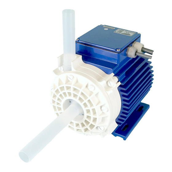
® User Manual for DuraLev R65S www.levitronix.com 2 Specifications 2.1 Specification of Components Figure 1: Pump system with standard components System Name Article # Pump Head Controller Motor Note DuraLev-R65S.1 100-91056 LPP-2000.16 LPC-2000.1-10 LPM-2000.12 Certifications: CE Table 1: Standard system configuration Pos. -
Page 5: Standard System Configurations
Overvoltage category II the mains supply Surge immunity according to EN 61000-4-5 Pollution degree Wet location Motor surface Table 4: Environmental conditions for pump system ® Note 1: Contact Levitronix technical department (see Section 7) for outdoor usage. PL-4064-00, Rev00, DCO# 22-264... -
Page 6: Pressure-Flow Curves
® User Manual for DuraLev R65S www.levitronix.com 2.4 Pressure-Flow Curves [gallons/min] Specific gravity = 1 g/cm 7900 rpm Viscosity = 0.7 cP Liquid Temp.: 40 C Pump Head: LPP-2000.16 7000 rpm [bar] 6000 rpm [psi] 5000 rpm 4000 rpm [liters/min] Figure 3: Pressure/flow curves for pump head LPP-2000.16... -
Page 7: Maximum Static Pressure For Pump Heads
® User Manual for DuraLev R65S www.levitronix.com 2.6 Maximum Static Pressure for Pump Heads [°F] [bar] [psi] Safety Factor = 1.3 (according to EN12162) Burst pressure is significantly higher. Ambient Temp = 25 C Note: Pressure limit only valid for pump head mounted on motor Liquid Temperature in [°C]... -
Page 8: Basic Dimensions Of Main Components
® User Manual for DuraLev R65S www.levitronix.com 2.7 Basic Dimensions of Main Components Spec. Pump Head Screws: Spec. Pump Motor Screws: Dimensions: 8x M8x40 Dimensions: 4x M8x30 Material: Stainless Steel PTFE Coated Material: Stainless Steel PTFE Coated Torque Spec.: 100 Ncm Torque Spec.: 60 Ncm... - Page 9 ® User Manual for DuraLev R65S www.levitronix.com Air Connection Port: NPT ¼“ with max. depth = 14mm Figure 7: Basic dimensions (in mm and [inch]) Motor LPM-2000 with Air Cooling Module ACM-4.2 Cable Cable OD Cable OD Minimum Bending Radius...
-
Page 10: Engineering Information
® User Manual for DuraLev R65S www.levitronix.com 3 Engineering Information 3.1 Sealing and Material Concept Figure 9: Sealing and material concept for system (LPM-2000.10 motor with pump head LPP-2000.16) Item System Materials Component Description Pump casing (lid and bottom, 1” Tube) -
Page 11: Ac Supply And Power Consumption
® User Manual for DuraLev R65S www.levitronix.com 3.2 AC Supply and Power Consumption 3.2.1 Power Consumption [gpm] 1400 Specific gravity = 1 g/cm 1200 Viscosity = ~ 0.7 cP Liquid Temp.: 40 C 7900 rpm 1000 7000 rpm 6000 rpm... -
Page 12: Earth Leakage Current
® User Manual for DuraLev R65S www.levitronix.com Situation t Value in [A Peak Value in [A] Switch-on after complete discharge of controller (> 60 s). For this case inrush current limiter in the controller are active. Switch-on after in-complete discharge (< 60 s, worst case) For this case inrush current limiter in the controller are not active. -
Page 13: Thermal Management
® User Manual for DuraLev R65S www.levitronix.com 3.4 Thermal Management 3.4.1 Motor Temperature The motor temperature depends on the ambient and liquid temperature, as well as on the hydraulic operation point and the characteristics (viscosity and density) of the liquid. Figure 13 illustrates the temperature characteristics for aqueous liquids at room temperature. - Page 14 ® User Manual for DuraLev R65S www.levitronix.com The above curves are measurements of the motor temperature at certain liquid and ambient temperatures. Equation (Eq. 1) shows how to calculate the motor temperature for other liquid and ambient temperatures based on these curves.
-
Page 15: Controller Temperature
® User Manual for DuraLev R65S www.levitronix.com 3.4.2 Controller Temperature Depending on the ambient temperature and the placement of the controller additional cooling may be required (see Figure 15). To improve cooling of the controller, place the device into a moving air stream. If the controller is mounted in a compact area or adjacent to additional heat sources (e.g. -
Page 16: Hydraulic Circuit Design
Figure 16: Avoidance of stress forces and torques at the inlet and outlet of the pump head ® Contact the Levitronix Technical Service department (see Section 7) for more detailed considerations and support on the design of the hydraulic circuit. -
Page 17: Installation
® User Manual for DuraLev R65S www.levitronix.com 4 Installation 4.1 Electrical Installation of Controller 4.1.1 Overview The LPC-2000 controller has signal processor controlled power converters with switched inverters for the drive and the bearing windings of the motor. The signal processor allows precise control of pump speed and impeller position. -
Page 18: General Installation Instructions
® User Manual for DuraLev R65S www.levitronix.com 4.1.2 General Installation Instructions WARNING Hazardous voltage may be present. Always isolate the electrical power supply before making or changing connections to the unit. To remove the power it is recommended to use an isolating device. -
Page 19: Electrical Installation Of Controller For Standalone Operation
® User Manual for DuraLev R65S www.levitronix.com 4.1.3 Electrical Installation of Controller for Standalone Operation For standalone operation the LPC-2000.1 is disabled when power is turned on. It can be enabled manually by using the “UP” button on the display. If the controller shall be enabled automatically, when power is applied the “ENABLE”... -
Page 20: Mechanical Installation Of The Pump/Motor
If explosive flammable gases are present, place the controller in an explosion-proof cabinet. CAUTION ® Do not under any circumstances open the controller. Levitronix does not assume responsibility for any damage, which occurs under such circumstances. PL-4064-00, Rev00, DCO# 22-264... -
Page 21: Operation
® User Manual for DuraLev R65S www.levitronix.com 5 Operation 5.1 State Diagram of Controller The controller LPC-2000.1 allows stand-alone operation with manual speed setting (“Button Control Mode”) as well as extended operation with analog speed setting (“Analog Control Mode”). Figure 22 shows the state diagram which can be controlled with the manual buttons and the signals on the “USER INTERFACE”... -
Page 22: Standalone Operation (Button Control Mode)
® User Manual for DuraLev R65S www.levitronix.com 5.2 Standalone Operation (Button Control Mode) ▪ When applying power the system defaults into the “Button Control Mode” and goes into the status “OFF ButtonControl” according to Figure 22. Levitation is disabled and the display indicates “OF”. -
Page 23: Extended Operation ("Analog Control Mode")
® User Manual for DuraLev R65S www.levitronix.com 5.3 Extended Operation (“Analog Control Mode”) ▪ In order to be able to control the pump with external signals (PLC) the mode “Analog Control Mode” has to be set with the display buttons. The “UP” and “Down” buttons have to be pressed simultaneously during 5 seconds. The display should feedback the change by blinking between the stored speed value and “An”. -
Page 24: Troubleshooting
- A digital output on the “USER INTERFACE” connector (“Status”) indicates if the system is active. However, the source of an error cannot be identified by this signal 7 Technical Support For troubleshooting, support and detailed technical information contact Levitronix Technical Service Department: ... -
Page 25: Symbols And Signal Words
® User Manual for DuraLev R65S www.levitronix.com 8.2 Symbols and Signal Words Symbol / Description Type Source Signal Word Indication of an imminently hazardous situation that, if DANGER not avoided, will result in death or severe injury. Signal word SEMI S1-0701...
Need help?
Do you have a question about the DuraLev R65S and is the answer not in the manual?
Questions and answers