Advertisement
Quick Links
Advertisement

Related Manuals for TMG TMG-GH2030BL


Summary of Contents for TMG TMG-GH2030BL
- Page 1 Main Specifications: Main Specifications : Page 0 of...
-
Page 2: Main Specifications
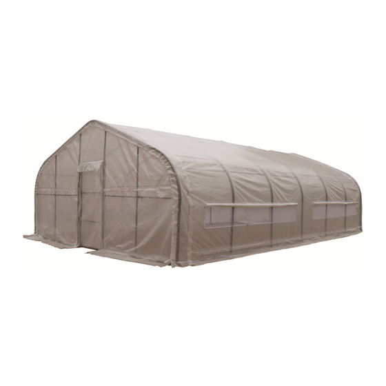
Main Specifications : - Assembly size : W6 x L9 x H3 (m) / W20 x L30 x H10 (ft) - Shoulder wall clearance height : 1.25 m / 4.1ft Front roll up door : W1.1 x H2 (m) / W3.6 x H6.6 (ft) Prior to assembly Please read the instructions carefully before installation. - Page 3 TMG-GH2030BL Part List Parts Graphical Description code Peak arch tube Upper rafter tube (middle and rear truss) Upper rafter tube (front truss) Shoulder tube (middle truss) Lower rafter tube (front and rear truss) Roof purlin (horizontal tube) Roof purlin (horizontal tube)
- Page 4 Baseplate (middle truss) Door frame lower tube (front truss) Door frame lower tube (front and rear truss) Door frame lower tube (front truss) Door frame lower tube (front truss) Door frame upper tube (front truss) Door frame upper tube (rear truss) Door frame upper tube (front truss) Door frame upper horizontal...
- Page 5 Bottom tension bar (front cover) Bottom tension bar (rear cover) Diagonal bracing bar (1st and last span) Tube clamp Tube clamp Door frame column tube Door frame column tube Door horizontal tube Expansion bolt M10x100mm (head diameter Hex bolt M10x60mm Mushroom head hexagon socket head bolt M6x60mm Mushroom head hexagon...
- Page 6 Hex bolt M8x60mm Hex bolt M8x50mm Hex bolt M8x80mm Door cover Water plug Water plug Water plug Top cover Front cover panel Rear cover panel Braided rope 1 bundle Allen key Page 5 of...
- Page 7 Mark the ground in the final building location with a line showing the positions of base plates, front, and rear doors. All lines should be drawn from center to center of all baseplate tubes. Diagonal line X must be equal to Y. ...
- Page 8 Step 2 : Assemble all trusses The building includes 7 trusses : (1) front truss, (1) rear truss, and (5) middle trusses. The front and the rear truss are to install with the fabric panel (#23 and #23A). Parts used to install the front truss in this step (refer to Figure 2) : (1) Peak arch tube (#1) (2) Upper rafter tube (#2A)
- Page 9 Figure 3 Parts used to install (5) middle trusses in this step (refer to Figure 4). (1x5) Peak arch tube (#1) (2x5) Upper rafter tube (#2) (2x5) Shoulder tube (#3) (2x5) Lower rafter tube (#4) (1x5) Ceiling cross bar (#11) (12x5) Hex bolt (#17) (2x5) Hex bolt (#19) Figure 4...
- Page 10 Lay down all (7) trusses on the ground as figure 5 when the assembly is all completed and before moving to next step (refer to Figure 5). Figure 5 Step 3 : Put up the front (1st) truss Use of a crane or forklift is recommended, otherwise a team can use ropes to lift the trusses, but you have to make sure it is safe, and have enough manpower.
- Page 11 Step 4 : Put up the rest trusses Refer to Step 3 to put up the rest trusses, connect all purlins (#5) and (#5A) with bolt (#18) and bolt (#19) secure all bolts firmly on each span before going to next truss (refer to Figure7).
- Page 12 Figure 8 Step 6 : Install the remaining parts on the front truss (refer to Figure 9) Parts used in this step : (1) Door frame lower tube (#8) (1) Door frame lower tube (#8B) (2) Door frame upper tube (#9) (2) Door frame upper tube (#9B) (4) Door frame horizontal tube (#10) (1) Door frame cross pull tube (#11A)
- Page 13 Figure 9 Assemble the sliding door. Fix the door column (#14) and (#14A) on the cross pull tube (#15) with bolts (#18A)( refer to Figure 10). Parts used in this step : (1) Door frame column tube (#14) (1) Door frame column tube (#14A) (4) Door horizontal tube (#15) (8) Mushroom head hexagon socket head bolt (#18A)
- Page 14 Sliding door installation. The assembled door cover cloth (#20) of the sliding door cover is fixed on the door frame of the front truss through the hinge. (refer to Figure Figure 11 Step 7 : Install the remaining parts on the rear truss ...
- Page 15 Figure 12 Step 8 : Install front cover panel and sliding door Note: Figure 13 is the inside view! Lift the fabric panel (#23), starting from the center point (the highest ridge point) of the frame, tie the panel firmly to the truss with a rope (#24) through the grommet, and then tie one end of (#24) to the truss.
- Page 16 Step 9 : Install rear cover panel Use rope (#24) to lift up the rear cover (#23A) from the center grommet and tie it firmly to the truss tube and spread toward both sides through each grommet along the tube (refer to Figure 14).
- Page 17 Step 11 : Stretch and tighten top cover The roof cover must be stretched and tied to the front and rear truss by rope going through the flap grommets on the cover. Start from the top center and go toward both side on each end.
Need help?
Do you have a question about the TMG-GH2030BL and is the answer not in the manual?
Questions and answers