Advertisement
Advertisement
Table of Contents

Subscribe to Our Youtube Channel
Related Manuals for TMG TMG-GH2030


Summary of Contents for TMG TMG-GH2030
- Page 1 www.tmgindustrial.com 0/24 TOLL FREE:1-877-761-2819...
-
Page 2: Main Specifications
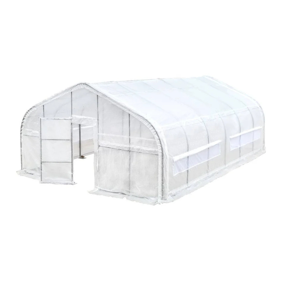
MAIN SPECIFICATIONS : Assembly size : W6 x L9 x H3 (m) / W19.7 x L29.5 x H9.8(ft) Shoulder wall clearance height : 1.25 m / 4.1ft Front roll up door : W1.1 x H2 (m) / W3.6 x H6.6 (ft) ... - Page 3 The layout of foundation(two) Note: the ground anchor is installed on the the ground anchor is installed on the cement block. www.tmgindustrial.com www.tmgindustrial.com 2/24 TOLL FREE:1 TOLL FREE:1-877-761-2819...
- Page 4 Baseplate layout. PRIOR TO ASSEMBLY Please read the instructions carefully before installation. It is important to follow your local safety regulations and industry standards during installation. Regulations may include but are not limited to : Safety helmets, protective eyewear, and clothing. ...
- Page 5 TMG-GH2030 PART LIST PARTS GRAPHICAL GRAPHICAL DESCRIPTION LENGTH CODE Peak arch tube φ φ48x1154mm Upper rafter tube φ φ48x1980mm (middle and rear trusses) Upper rafter tube φ φ48x1980mm (front truss) Shoulder tube φ φ48x1335mm (middle truss) Lower rafter tube φ...
- Page 6 Ratchet Tensioning tube φ32x1993mm Tensioning tube φ32x1360mm Door frame lower tube φ32x1922mm (front truss) Door frame lower tube φ32x1157mm Door frame lower tube φ32x1922mm (front truss) Door frame lower tube φ32x1265mm (front truss) Door frame upper tube φ32x886mm (front truss) Door frame upper tube φ32x1429mm (rear truss)
- Page 7 Bottom tension bar φ φ25x1925mm (rear cover) Diagonal bracing bar φ φ25x1910mm (1st and last span) Tube clamp φ48mm Tube clamp φ32mm Door frame column tube 30x30x1925mm 30x30x1925mm Door frame column tube 30x30x1925mm 30x30x1925mm Door horizontal tube 30x30x996mm 30x30x996mm Expansion bolt φ14x100mm Hex bolt M10x60mm...
- Page 8 Water plug φ32mm Water plug 30x30mm Water plug φ25mm Top cover W90400 90400xL10520mm Front cover panel W3220 3220xL59520mm Rear cover panel W3220 3220xL59520mm Braided rope φ8x100m Ratchet straps W38xL800mm W38xL800mm Allen key Scratch resistant tape www.tmgindustrial.com www.tmgindustrial.com 7/24 TOLL FREE:1 TOLL FREE:1-877-761-2819...
-
Page 9: Installation Steps
INSTALLATION STEPS STEP 1 : REVIEW THE WHOLE STRUCTURE AND CHOOSE THE PROPER INSTALLATION SITE. Installation diagram of expansion bolt. PART PART www.tmgindustrial.com 8/24 TOLL FREE:1-877-761-2819... - Page 10 STEP 2 : ASSEMBLE ALL TRUSSES. The building includes 7 trusses: (1) front truss, (1) rear truss, and ( trusses: (1) front truss, (1) rear truss, and (5) middle trusses. ) middle trusses. install front truss. PART PART www.tmgindustrial.com www.tmgindustrial.com 9/24...
- Page 11 install rear truss. PART PART www.tmgindustrial.com www.tmgindustrial.com 10/24 TOLL FREE:1 TOLL FREE:1-877-761-2819...
- Page 12 Install (5) middle trusses. PART PART 12x5 www.tmgindustrial.com www.tmgindustrial.com 11/24 TOLL FREE:1 TOLL FREE:1-877-761-2819...
- Page 13 Lay down all (7) trusses on the ground when the assembly is all completed and before moving to next step, and then wrap (#26) around the sharp points of the joint to avoid friction between the fabric and the interface, resulting in fabric damage.
- Page 14 STEP 3 : PUT UP THE FRONT (1ST) TRUSS. Put up the truss, use hex bolt (#17) to secure the truss to the base plates. PART www.tmgindustrial.com 13/24 TOLL FREE:1-877-761-2819...
- Page 15 Refer to Step 3 to put up the rest trusses, connect all purlins to put up the rest trusses, connect all purlins. PART www.tmgindustrial.com www.tmgindustrial.com 14/24 TOLL FREE:1 TOLL FREE:1-877-761-2819...
- Page 16 STEP 4 : INSTALL THE DIAGONAL BRACING BARS (#13) : INSTALL THE DIAGONAL BRACING BARS (#13). Connect diagonal bracing bar (#13) on the first and last span between the shoulder tube and Connect diagonal bracing bar (#13) on the first and last span between the shoulder tube and Connect diagonal bracing bar (#13) on the first and last span between the shoulder tube and lower rafter tube ...
- Page 17 STEP 5 : INSTALL THE REMAINING PARTS ON THE AINING PARTS ON THE FRONT TRUSS. PART PART www.tmgindustrial.com www.tmgindustrial.com 16/24 TOLL FREE:1 TOLL FREE:1-877-761-2819...
- Page 18 STEP 6 : INSTALL THE REMAINING PARTS ON THE REAR TRUSS AINING PARTS ON THE REAR TRUSS. PART PART www.tmgindustrial.com www.tmgindustrial.com 17/24 TOLL FREE:1 TOLL FREE:1-877-761-2819...
- Page 19 STEP 7 : INSTALL FRONT COVER PANEL, WHAT YOU SE : INSTALL FRONT COVER PANEL, WHAT YOU SEE IN THIS PICTURE IS THE INSIDE. Use rope (#24) to lift up the front front cover (#23) from the center grommet and tie it firmly to the truss tube and ) from the center grommet and tie it firmly to the truss tube and ...
- Page 20 Assemble the sliding door. Fix the door column (#14) and (#14A) on the cross pull tube (#15) with bolts Assemble the sliding door. Fix the door column (#14) and (#14A) on the cross pull tube (#15) with bolts Assemble the sliding door. Fix the door column (#14) and (#14A) on the cross pull tube (#15) with bolts ...
- Page 21 Sliding door installation. The assembled door cover cloth (#20) of the sliding door cover is fixed on the door frame of the front truss through the hinge. www.tmgindustrial.com 20/24 TOLL FREE:1-877-761-2819...
- Page 22 STEP 8 : INSTALL REAR COVER PANEL, WHAT YOU SEE IN THIS PICTURE IS THE , WHAT YOU SEE IN THIS PICTURE IS THE INSIDE. Use rope (#24) to lift up the rear cover (#23A) from Use rope (#24) to lift up the rear cover (#23A) from the center grommet and tie it firmly to the truss tube and the center grommet and tie it firmly to the truss tube and ...
- Page 23 STEP 9 : INSTALL THE TOP COVER (#22 : INSTALL THE TOP COVER (#22). DO NOT INSTALL THE COVER DURING WINDY WEATHER! DO NOT INSTALL THE COVER DURING WINDY WEATHER! Unpack the top cover and place it along one of the long sides of the structure. Unpack the top cover and place it along one of the long sides of the structure.
- Page 24 STEP 10 : STRETCH AND TIGHTEN TOP COVER : STRETCH AND TIGHTEN TOP COVER. The roof cover must be stretched and tied to the The roof cover must be stretched and tied to the front and rear truss by rope going through the flap grommets front and rear truss by rope going through the flap grommets ...
-
Page 25: After The Installation
AFTER THE INSTALLATION. Inspect the building periodically to make sure the parts are firmly fixed and the whole building is well supported. Check all bolts and hardware connectors to make sure they are in place and tightened. Check the base plates, adjust the ropes if necessary and clean the cover regularly.
Need help?
Do you have a question about the TMG-GH2030 and is the answer not in the manual?
Questions and answers