Advertisement
Quick Links
Advertisement

Subscribe to Our Youtube Channel
Related Manuals for TMG TMG-GH826


Summary of Contents for TMG TMG-GH826
- Page 1 0/16 Toll Free:1-877-761-2819 ►www.tmgindustrial.com...
-
Page 2: Main Specifications
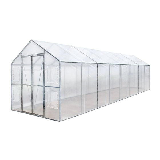
MAIN SPECIFICATIONS : Overall assembled size : W2.4 x L8 x H2.3 (m) / 7.87 x 26.25 x 7.54 (ft) Shoulder height : 1.58m / 5.18 ft Ridge peak height : 2.3m / 7.54 ft The front and back doors : 1.1 x 1.8 (m) / 3.6 x 5.9 (ft) ... - Page 3 TMG-GH826 PART LIST PARTS GRAPHICAL DESCRIPTION LENGTH CODE Truss upper eave beam L1398mm pipe Front and rear door truss L1398mm upper eave beam pipe Lower straight pipe of L1555mm middle truss Lower straight pipe of front L1555mm and rear doors...
- Page 4 L-shaped connecting plate L90mm Triangular fixing plate L150mm Riding clip L134mm Expansion bolt φ8x100mm (not included) Mushroom head hexagon M6x45mm socket bolt Inner hexagon spanner Hex Bolt M10x30mm Compression strip L2000mm Scratch resistant tape Cross round head drill tail M5x15mm 1198 tapping screw Hinge...
-
Page 5: Installation Steps
INSTALLATION STEPS STEP 1 : FOUNDATION PIPE INSTALLATION. Installation diagram of expansion bolt. PART PART 4/16 Toll Free:1-877-761-2819 ►www.tmgindustrial.com... - Page 6 STEP 2 : INSTALL THE LOWER STRAIGHT PIPE. In this step, do not tighten the screws, and then tighten them when positioning later! PART 5/16 Toll Free:1-877-761-2819 ►www.tmgindustrial.com...
- Page 7 STEP 3 : INSTALL THE UPPER EAVE BEAM PIPE (#1、#1A) AND CROSS PULL PIPE OF TRUSS(#4). In this step, do not tighten the screws, and then tighten them when positioning later! PART PART 6/16 Toll Free:1-877-761-2819 ►www.tmgindustrial.com...
- Page 8 STEP 4 : ASSEMBLE THE LIMIT BAR (#23), AND USE THE LIMIT BAR TO FIX THE TRUSS POSITION AND TIGHTEN THE BOLTS. Assemble the limit rod (#23) with connecting plate (#23A) and self-tapping screw (#20). Fix the truss position with the limit bar (#23) in sequence from one to nine and tighten the bolts. ...
- Page 9 STEP 5 : WRAP (#19) AROUND THE SHARP POINTS OF THE JOINT TO AVOID FRICTION BETWEEN THE FABRIC AND THE INTERFACE. PART 8/16 Toll Free:1-877-761-2819 ►www.tmgindustrial.com...
- Page 10 STEP 6 : INSTALL THE FRONT AND REAR TRUSSES. PART PART 14x2 9/16 Toll Free:1-877-761-2819 ►www.tmgindustrial.com...
- Page 11 STEP 7 : ASSEMBLE 4 DOOR FRAMES. PART 16x4 10/16 Toll Free:1-877-761-2819 ►www.tmgindustrial.com...
- Page 12 STEP 8 : FRONT AND REAR DOOR INSTALLATION. Pay attention to the outward opening of the door during installation! PART 32x2 11/16 Toll Free:1-877-761-2819 ►www.tmgindustrial.com...
- Page 13 STEP 9 : INSTALL FRONT AND REAR COVER PANEL. Trim the length of compression band (#18) according to the site requirements. According to the sequence of steps, use the compression belt (#18) to fix the cover plate from ① to ⑥, first ...
- Page 14 STEP 10 : INSTALL THE DOOR HANDLE AND DOOR LATCH. Cut the door film as shown. PART PART 36x2 13/16 Toll Free:1-877-761-2819 ►www.tmgindustrial.com...
- Page 15 STEP 11 : INSTALL THE TOP COVER (#25D). DO NOT INSTALL THE COVER DURING WINDY WEATHER! Stretch and adjust the cover from back and forth, to make sure it is square and centered. Unpack the top cover and place it along one of the long sides of the structure. ...
- Page 16 STEP 12 : TIGHTEN AND FIX THE TOP CLOTH. The Compression strip (#18) at the front and rear stops are nailed to the front of the front and rear crotch cloth. The spacing of each self Cross round head drill tail tapping screw shall be kept within 150mm. Nail a circle of Compression strip (#18) on the third and seventh truss.
-
Page 17: After The Installation
AFTER THE INSTALLATION Walk around and inspect the shelter periodically to make sure all components are still firmly secured and the whole shelter is well supported. Check all bolts and nuts as well as all connection points to make sure they are all in good position.
Need help?
Do you have a question about the TMG-GH826 and is the answer not in the manual?
Questions and answers