
Related Manuals for AmeriWater Central Sterile RO3X


Summary of Contents for AmeriWater Central Sterile RO3X
- Page 1 Operation & Maintenance Manual Central Sterile RO3X 00HCRO3X402 3345 Stop 8 Rd, Dayton, OH 45414 | 800 535 5585 | www.ameriwater.com 098-0002 Rev B Manufactured With Pride in the USA...
-
Page 3: Table Of Contents
TABLE OF CONTENTS HCRO3X TABLE OF CONTENTS TABLE OF CONTENTS ..........................1 USER INFORMATION........................3 Manual Definitions ..........................3 Introduction ............................3 Electrical Leakage Standards ......................4 Cautionary Symbols .......................... 4 Warranty Policy ..........................4 TECHNICAL INFORMATION ......................5 System Specifications ........................5 Environmental Conditions Anticipated ................... - Page 4 TABLE OF CONTENTS HCRO3X 6.1.1 Disinfecting the RO3X ......................... 25 A Word about Hydrogen Peroxide/Peroxyacetic Acid ..............27 Membrane Flush Feature (Auto Flush) ..................29 CLEAN IN PLACE (CIP) ........................30 RO CONTROLLER .......................... 32 Front Panel Controls and Indicators ..................... 32 Controller Operation ........................
-
Page 5: User Information
Please notify AmeriWater if any problems are encountered. Please read the Operation Manual before using the system. Contact AmeriWater Customer Service with any questions at 1-800-535-5585 Monday through Friday 8:00 a.m. to 5:00 p.m. Eastern Time. -
Page 6: Electrical Leakage Standards
USER INFORMATION HCRO3X 1.3 Electrical Leakage Standards The AmeriWater RO water treatment systems comply with the IEC 61010-1 Standards for Product Safety and Construction. The cabinet of the RO is PVC for additional operator safety. The RO is compliant with IEC 61010-1 Safe Current Limits. All major components of the RO (controller, pump, solenoid valve, anti-scalant pump, etc.) are UL listed. -
Page 7: Technical Information
TECHNICAL INFORMATION HCRO3X TECHNICAL INFORMATION 2.1 System Specifications Ideal, minimum, and maximum Min = 41° F (5° C) incoming water temperature Max = 90° F (33° C) Ideal Temperature = 77° F (25° C) Pre-filter gauge pressure (when the RO is running) Minimum 20 PSI Maximum... -
Page 8: Environmental Conditions Anticipated
TECHNICAL INFORMATION HCRO3X 2.2 Environmental Conditions Anticipated This device is intended to be used under the following conditions: Indoor use • Altitude up to 6562 feet (2000 m) • Temperature between 41°F and 104°F (5°C and 40°C) • Maximum relative humidity 80% for temperatures up to 87.8°F (31°C) decreasing linearly to •... -
Page 9: System Components
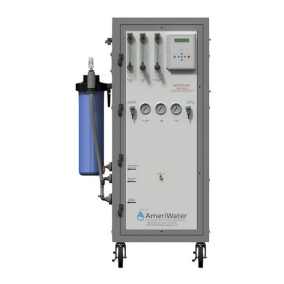
TECHNICAL INFORMATION HCRO3X 2.5 System Components Figure 1. External Front View 098-0002 Rev B... - Page 10 TECHNICAL INFORMATION HCRO3X IDENTIFICATION OF COMPONENTS (Figure 1) SIDE ENTRY HOODS: External connection for float level switches (4 pin connection) and PT Pump power connection (5 pin connection). PRE-FILTER INLET GAUGE – Gauge that measures the pressure in pounds per square inch (PSI) of the incoming tap water as it enters the carbon block pre-filters.
- Page 11 TECHNICAL INFORMATION HCRO3X REJECT PRESSURE – Gauge that measures the pressure in pounds per square inch (PSI) from the reject of the membranes. CONTROLLER – Control mechanism for the RO. RECIRCULATION GPM – Flowmeter that indicates the flow of water that is recirculated back to the pump’s inlet.
- Page 12 CLEAN IN PLACE SWITCH (ALARM FAULT OVERRIDE): When the Clean In Place (CIP) switch is placed to the ON position, all RO fail-safe modes are disabled for low-pressure membrane cleaning with the optional AmeriWater Clean In Place system (P/N 00CIP2). The controller will display a warning that the CIP mode is active.
-
Page 13: Electical Schematic
TECHNICAL INFORMATION HCRO3X 2.6 Electical Schematic Figure 3: Electrical Diagram, RO3X 098-0002 Rev B... -
Page 14: Flow Schematic
TECHNICAL INFORMATION HCRO3X 2.7 Flow Schematic Figure 4: RO3X Flow Schematic 098-0002 Rev B... -
Page 15: System Installation
SYSTEM INSTALLATION HCRO3X SYSTEM INSTALLATION 3.1 Pre-Installation Requirements Utility requirements; Plumbing: ¾” ball valve with NPT threads and dynamic pressure of at least 20 PSI at 10 GPM. Electrical: see Section 2.1. Hot and cold city/tap water supply line flushed and free of debris before equipment installation. - Page 16 SYSTEM INSTALLATION HCRO3X The RO system may be equipped with a pretreatment system to remove chlorine. It is important to test for chlorine at the chloramine sample port periodically. Chlorine will deteriorate the membrane and cause system failure. It is recommended to use a chlorine test strip.
-
Page 17: Pt401 Installation
RO in after the pre-filters. Fill the solution tank with the supplied chemical and follow the pump priming procedure. NOTE: Use AmeriWater, CP Grade (Chemically Pure) chemicals only! CAUTION: Disconnect ALL power supplies to the RO prior to connecting the metering pump to the RO control or electrical shock could result. -
Page 18: System Start-Up Procedures
ON position during normal operation, all RO fail-safe modes will be disabled, and damage to the RO. Ameriwater recommends installing a sediment filter added as pretreatment for the RO. Minimize the opportunities for bacterial growth between uses! Whenever the RO is not used for a period of several hours, and connected to a Storage Tank, the “Membrane Flush... - Page 19 An audible alarm sounds whenever water quality drops to an unacceptable level. WARNING: The AmeriWater model RO3X is considered a non-portable device. It can be connected to a Storage Tank system. For this reason, there is a divert to drain on this model.
- Page 20 SYSTEM START-UP PROCEDURES HCRO3X NOTE: Before connecting incoming feed water to RO, ensure feed water line is routed to drain and until the water is clear to prevent rusty water from clogging the system. Connect the RO incoming tap water hose to the potable cold water supply using the incoming tap water hose and fittings supplied.
- Page 21 SYSTEM START-UP PROCEDURES HCRO3X �������������� �������� (������) �� 100% = ���� ���������������� �������� �������� (������) With the RO Operating, adjust the valve on the recirculation flowmeter until the recirculation flow rate is approximately one-third of the reject flow rate. The user can verify that the RO is operating correctly by checking the flowmeters, the controller, and the inlet and outlet pressure gauges.
-
Page 22: Pt401 Priming Procedure
SYSTEM START-UP PROCEDURES HCRO3X where it no longer meets the requirements of this standard. AmeriWater offers information about ultra-pure water piping to prevent the degradation of product water in a water loop. 4.3.1 PT401 Priming Procedure WARNING: Do not use the PT401 anti-scalant if your system has softened water. Turn off the system by depressing the on / off button on the PT401 pump. -
Page 23: System Shutdown
SYSTEM START-UP PROCEDURES HCRO3X At the stroke rate of ten, the PT401 injection pump will put about 30 milliliters (approximately 10 liquid ounces) per hour into the RO incoming water stream. Repeat these steps as necessary when the system is started after sitting for extended periods or the PT401 Bottle is empty and air has drawn into the pump. -
Page 24: Operation And Monitoring
OPERATION AND MONITORING HCRO3X OPERATION AND MONITORING 5.1 Operation Once the system has been started, the RO will continue to make water until the high-level float switch is tripped on the storage tank. At this point, the RO will be placed into standby (tank full) until the mid-level float switch is tripped. - Page 25 OPERATION AND MONITORING HCRO3X warranty. The follow page shows a sample log. FEED WATER QUALITY Parameters Results Date Initials Conductivity (uS) Record Hardness (GPG) Record Chlorine (ppm) Record Record PRE-FILTRATION Parameters Results Date Initials Blend Valve Temperature 77°F ± 5°F Chlorine Test ≤...
-
Page 26: Aami Monitoring
DISINFECTION AmeriWater recommends that all HCRO systems should be disinfected monthly. Additionally, the system should be disinfected if it has not been: flushed at least every 8 hours; or “preserved”. The following sections will outline the disinfection steps. -
Page 27: Disinfecting The Ro3X
DISINFECTION HCRO3X 6.1.1 Disinfecting the RO3X Switch off the RO3X by pressing the POWER key (the display will show STANDBY). WARNING: The disinfection mode will allow PAA to flow through the PRODUCT WATER hose. This is to allow disinfection of the hoses. To disinfect only the RO3X that is connected to a Storage Tank, disconnect the PRODUCT WATER hose from the tank and place along with the... - Page 28 DISINFECTION HCRO3X approximately 2 minutes. Continue holding the ENTER key until the PAA container is empty, then immediately release the ENTER key. NOTE: The ENTER key must be held until all the PAA is drawn into the RO. a. Avoid stopping and starting the disinfect function which may cause a thermal overload of the RO pump.
-
Page 29: A Word About Hydrogen Peroxide/Peroxyacetic Acid
Continue rinsing and testing with test strips until all test strips show a negative residual result (no color change) to ensure that there are NO traces of PAA disinfecting solution remaining in the entire water system. AmeriWater recommends using Renal Check PX Test Strips (P/N 97PX20501). - Page 30 DISINFECTION HCRO3X Disposal of Outdated Hydrogen Peroxide/Peroxyacetic Acid: Put on rubber gloves, apron, and goggles. CAUTION: Exposure to PAA concentrate or solution may cause severe chemical burns to skin or eyes. Start a flow of cold tap water to dilute the PAA as it flows down the sink drain. Slowly and carefully pour the disinfecting solution down the drain, taking care to avoid spills, splashes, or breathing the vapors.
-
Page 31: Membrane Flush Feature (Auto Flush)
DISINFECTION HCRO3X 6.3 Membrane Flush Feature (Auto Flush) The MEMBRANE FLUSH FEATURE is the preferred means for minimizing bacterial growth for the RO3X during periods of low water usage. Ordinarily these sizes of RO are connected to a loop or storage tank only having 1-2 days of non-use when water usage is not necessary. -
Page 32: Clean In Place (Cip)
CLEAN IN PLACE (CIP) HCRO3X CLEAN IN PLACE (CIP) Move the CLEAN IN PLACE SWITCH (inside the RO on the back of the controller) to the ON position. CAUTION: To avoid electrical shock, always unplug the RO system before opening the access panel or the face of the electrical controller. - Page 33 CLEAN IN PLACE (CIP) HCRO3X Turn off the RO and CIP Pump and disconnect the REJECT TO DRAIN HOSE from the CIP Cleaning Drum. Direct the REJECT TO DRAIN HOSE to a drain. Turn on the RO and CIP Pump and continue running to drain until the CIP Cleaning Drum is emptied.
-
Page 34: Controller
RO CONTROLLER HCRO3X RO CONTROLLER 8.1 Front Panel Controls and Indicators Figure 6: Control Panel DISPLAY Shows status of system. ALARM LAMP Flashes when fault causes an RO system shut down. On steady when a Set-point is exceeded that does not cause an RO system shut down. -
Page 35: Controller Operation
RO CONTROLLER HCRO3X Controller Operation GENERAL OPERATION The unit has 2 modes of operation, a standby mode and an operating mode that are controlled by the POWER key. In the standby mode, the unit is effectively off. All outputs are turned off and the display shows STANDBY. - Page 36 RO CONTROLLER HCRO3X OPERATING HOURS The current operating hours are shown on the bottom line. TEMPERATURE The current water temperature is shown on the bottom line to the right of operating hours. When the unit is in STANDBY due to a shut down condition, the reading is replaced with ‘---‘. WARNING MESSAGES Warning messages are also shown on the second line.
- Page 37 RO CONTROLLER HCRO3X tank full shut down condition. The TANK FULL OVERRIDE will divert all water to the drain, whether the water quality is good or bad coming into the RO. PRESSURE FAULT If the pressure fault input becomes active (closes) and stays active for the delay programmed in the PF Delay Set-point, the unit will shut down for a pressure fault.
-
Page 38: Controller Adjustments
It may be necessary to periodically calibrate the Conductivity. If the controller should require calibration, follow the instructions below. Please contact AmeriWater at 800-535-5585 or 937-461-8833 if you have any questions regarding the procedure. - Page 39 RO CONTROLLER HCRO3X Figure 7 098-0002 Rev B...
- Page 40 RO CONTROLLER HCRO3X Figure 8 098-0002 Rev B...
-
Page 41: Standard Set-Points
RO CONTROLLER HCRO3X 8.4 Standard Set-points FACTORY SET-POINT DESCRIPTION RANGE USER SETTING When this value is met or exceeded, Based on the alarm lamp will light and high 0-999 µS TDS/Cond Limit water TDS/Cond will show on the display. To or PPM* analysis. - Page 42 RO CONTROLLER HCRO3X FACTORY SET-POINT DESCRIPTION RANGE USER SETTING Allows adjustment of temperature Temp Offset reading by ±5 degrees. Selects display of temperature in °F or Temp UOM °C. 0 = °F, 1= °C. Selects if switch inputs are normally Switch Select open or normally closed.
-
Page 43: To Display Or Change Set-Points
8.5 To Display or Change Set-points NOTE: Please contact your AmeriWater representative prior to changing set-points. Refer to Figure 6 for the location of the keys used to display or change the Set-points and Figure 7 for the location of the write protect jumper, J3. For the unit to be able to accept a change in a Set-point, the shorting jumper must be in the WRITE PROTECT OFF position (center and left pins). - Page 44 R10 position with a replacement resistor, provided by AmeriWater. This replacement resistor can be identified by its color bands (Blue- Grey-Red-Gold). Alternatively, if you have an ohm-meter, the original resistor can be identified by its resistance value of 2.7 kΩ;...
-
Page 45: Maintenance
MAINTENANCE HCRO3X MAINTENANCE WARNING: If any component of the water treatment system is changed or replaced, the user should conduct appropriate tests to ensure that the revised system meets all standards to which it was initially tested. WARNING: Maintenance shall be performed by qualified personnel only. 9.1 Maintaining the System Use the following maintenance schedule: Frequency... - Page 46 MAINTENANCE HCRO3X Open the back panel of cabinet. Press release button on Product Water Manifold (Manifold located near top at back of left wall – looking in back of cabinet) to disconnect product water hose from all membranes being removed. Disconnect the pump feed and reject discharge hose from the membrane being replaced.
-
Page 47: Rinse Out Cycle
Turn on the RO. The rinse out cycle is now complete, and the RO is ready for use. WARNING: If the product water conductivity does not come out of alarm, do not use the system! Continue rinsing, or call AmeriWater for guidance. 098-0002 Rev B... -
Page 48: Troubleshooting And Repair
RO system. To assist you in quickly restoring your system into service, AmeriWater will send your replacement part out immediately and check your bad part when it comes in to verify if it is covered under your equipment warranty. - Page 49 TROUBLESHOOTING AND REPAIR HCRO3X PROBLEM POSSIBLE CAUSE CORRECTIVE ACTION 3. Pump motor or impeller 1 GPM. failing 2. Test the solenoid (Section 10.5). Replace the valve if it is defective (see Section 10.6). 3. Check PUMP PSI GAUGE to verify that it is within operating parameters.
-
Page 50: Controller Troubleshooting
When disconnecting or connecting any board or accessory, be sure power is unplugged. Before contacting AmeriWater for technical help, verify the programming of all Set-points, check the display and check the status of all lights and indicators. The more information available when you contact us, the easier it will be to determine the source of the problem. - Page 51 TROUBLESHOOTING AND REPAIR HCRO3X PROBLEM INVESTIGATION CORRECTIVE ACTION lit? 4. If yes, with a voltmeter, verify if there is power on the inlet terminals. Is there power? RO Pump Will Not Operate 1. Is the system in standby? 1. If no, replace the board. 2.
-
Page 52: Pump Repair
TROUBLESHOOTING AND REPAIR HCRO3X 10.3 Pump Repair The following procedures are instructions for removing the pump from the unit. Turn off the water supply and the RO. Unplug the power cord from the electrical outlet and turn off the wall disconnect for the high voltage. If the high voltage cannot be disconnected by a twist-lock plug, make sure there is a “lockout”... -
Page 53: Solenoid Test Procedure
TROUBLESHOOTING AND REPAIR HCRO3X Clean the threads from the fittings that were previously removed. Apply a suitable thread sealant and install into the cap. Insert the pump assembly and reconnect the pump to the frame using the unistrut clamps. Connect the membrane feed tubing and pump pressure gauge tubing to the pump housing outlet port (at the top), and tighten the ferrule nut. -
Page 54: Solenoid Valve Replacement
TROUBLESHOOTING AND REPAIR HCRO3X Hold in the ENTER KEY until water flows to the drain. If there is no water flow to the drain, the solenoid has failed closed. 10.6 Solenoid Valve Replacement For all valves, Feed, Disinfect, or Product Divert Solenoid Valves Turn off the RO by pressing the POWER key (the display will show STANDBY), unplug the 120 VAC power cord from the electrical outlet, turn off the wall disconnect, and place a lockout in the disconnect handle. -
Page 55: Spare Parts Listing
SPARE PARTS LISTING HCRO3X 11 SPARE PARTS LISTING Item # Description Part Number FLOWMETER 1-10 GPM 41530612 VALVED METER 1-10 GPM 41-0024 SIDE ENTRY HOOD 0167-0016 BALL VALVE 041003 PRESSURE GAUGE 0-100 PSI 43-0012 ½” HB x MPT ELBOW 14520406 ¾”... - Page 56 SPARE PARTS LISTING HCRO3X Figure 10 098-0002 Rev B...
- Page 57 SPARE PARTS LISTING HCRO3X Figure 11 Figure 12 098-0002 Rev B...
- Page 58 SPARE PARTS LISTING HCRO3X EXPLANATION OF THE 0013-0002 O-RING REPLACEMENT KIT FOR THE 24-0007 MEMBRANE HOUSING The 24-0007 membrane housing is purchased from (2) different vendors, Pureteck & Axeon. To identify the correct housing being used with your product, reference the pictures below. The 0013-0002 o-ring kit contains a quantity of (2) of the 24-0029 o-rings and a quantity of (2) of the 24-0028 u-packing seals that are used on the Pureteck membrane housing for the (2) end caps.
-
Page 59: California Proposition 65
Polyvinyl Chloride (PVC). The AmeriWater system you have purchased may contain PVC or stainless steel parts. While warnings are only required in the State of California, AmeriWater has initiated the use of Prop 65 labeling for all products to ensure compliance with California regulations. Please note that the above warning does not necessarily mean that the product that you have purchased is unsafe.
Need help?
Do you have a question about the Central Sterile RO3X and is the answer not in the manual?
Questions and answers