
Related Manuals for AmeriWater MediQA


Summary of Contents for AmeriWater MediQA
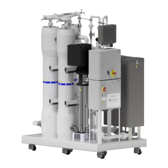
- Page 1 AmeriWater Diagnostic Guide The Water Purification Specialists MediQA Reverse Osmosis System 3345 Stop 8 Rd, Dayton, OH 45414 | 800 535 5585 | www.ameriwater.com 098-0010 Rev C Manufactured With Pride in The USA...
-
Page 3: Table Of Contents
IFU 98-9160A – Updating MediQA HMI Software with Jump Drive ....54 IFU 98-9084B – Heatsan-MediQA Fill Line Disinfection ........56 IFU 98-9085A – MediQA – Changing RO Cleaning Reminder Setting on HMI 58 IFU 98-9098B– AmeriClean Powder Membrane Cleaning Procedure ..... 62 Instructions for changing HMI clock on MediQA .......... -
Page 4: Component Identification
COMPONENT IDENTIFICATION 1.1 MSP Components 098-0010 Rev C... - Page 5 098-0010 Rev C...
- Page 6 098-0010 Rev C...
-
Page 7: Mdp Components
1.2 MDP Components 098-0010 Rev C... - Page 8 098-0010 Rev C...
- Page 9 098-0010 Rev C...
-
Page 10: Mediqa Operation Periods
Explanation Standby When the MediQA is not scheduled to be on and in TIMER mode, the system will be in Standby. The MediQA can also be set to “POWER ON STANDBY” for occasions when there are long periods without use. In standby mode the MediQA operates for 10 minutes every 2 hours, these values are user settable. -
Page 11: Flow Schematics
2.2 Flow Schematics 2.2.1 MSP Schematics 098-0010 Rev C... - Page 12 098-0010 Rev C...
- Page 13 098-0010 Rev C...
- Page 14 098-0010 Rev C...
- Page 15 098-0010 Rev C...
- Page 16 098-0010 Rev C...
- Page 17 098-0010 Rev C...
- Page 18 098-0010 Rev C...
- Page 19 098-0010 Rev C...
- Page 20 098-0010 Rev C...
- Page 21 098-0010 Rev C...
- Page 22 098-0010 Rev C...
- Page 23 098-0010 Rev C...
- Page 24 098-0010 Rev C...
-
Page 25: Mdp Schematics
2.2.2 MDP Schematics 098-0010 Rev C... - Page 26 098-0010 Rev C...
- Page 27 098-0010 Rev C...
- Page 28 098-0010 Rev C...
- Page 29 098-0010 Rev C...
- Page 30 098-0010 Rev C...
- Page 31 098-0010 Rev C...
- Page 32 098-0010 Rev C...
- Page 33 098-0010 Rev C...
- Page 34 098-0010 Rev C...
- Page 35 098-0010 Rev C...
- Page 36 098-0010 Rev C...
- Page 37 098-0010 Rev C...
-
Page 38: Plc Inputs And Outputs
PLC INPUTS AND OUTPUTS Input Description On meaning Off meaning Emergency Stop Relay Normal E-stop pushed in or not yet reset Stage 1 Pump Fault Fault Normal Stage 2 Pump Fault (MDP only) Fault Normal Base Level Float Closed (tank filled Open (tank filled less above base level float) than base level float) - Page 39 Output Description On meaning Off meaning Pump Run Stage 1 Pump on Pump off Pump Slow Stage 1 Pump running slow Pump off or full speed Pump Run Stage 2 (MDP only) Pump on Pump off Pump Slow Stage 2 (MDP only) Pump running slow Pump off or full speed...
-
Page 40: Valve Positions
VALVE POSITIONS Normal Operation: Ball Valve Flush Rinse Supply PSC - Product to Closed Closed Open Loop Valve LRV - Loop Return Open to return loop Open to return loop Open to return loop Valve water to tank water to tank water to tank CDV –... - Page 41 System Off Operation Note: The MediQA system uses a series of automated 2 and 3-way stainless steel valves to direct the water flow through the unit during each of the various stages of operation. These valves are marked with yellow indicators that represent the openings of the valve. The yellow markers are used as a visual indicator of the position of the ball valve as it relates to the flow of the water through the valve.
-
Page 42: Alarm Information And Checks
ALARM INFORMATION AND CHECKS ALARMS will stop machine operation. It is not possible to restart the machine without addressing the fault. Alarm Reason Checks Proposed Actions Description ALARMS RO1 Pump Stage 1 Pump pressure switch 1) RO1 Membranes are blocked 1) Check valve status Over Pressure (PS2) registers value higher than... - Page 43 Output Quality Output Quality Alarm Set-point 1) Check Output Quality Alarm set-point 1) Perform RO Heat Disinfection or Alarm Exceeded 2) Check output conductivity with Myron-L membrane chemical clean meter 2) Replace membranes 3) Profile membranes Tank Quality Tank Quality Alarm Set-point 1) Check Tank Quality Alarm set-point 1) Drain tank refill and perform extra Alarm...
- Page 44 RO Heat 2) Check if Heatsan is doing Heat 2) Change disinfection schedule so it Alarm Disinfection or Chemical Clean Disinfection while MediQA is doing Heat doesn’t occur simultaneously Disinfection or Chem Clean 3) Limit switch failure Heater Over...
-
Page 45: Warning Information And Checks
WARNING INFORMATION AND CHECKS Warnings are advisories. The machine will not stop but action should be taken to correct the fault. Warning Reason Checks Proposed Actions Description WARNINGS Time Date Not Timer mode is on but there are 1) RO Supply Schedule and RO Heat 1) Program times to schedule Set Warning no schedules set for either Supply... - Page 46 Output High Delivery Pressure Switch (PS1) 1) Permeate valve relief set too high 1) Adjust valve using Section 9.1 Pressure registers value higher than set- 2) Check pressure switch set-point by 2) Adjust set-point Warning point on pressure switch comparing gauge reading when warning X12 off occurs High Water...
- Page 47 Loop Flow High Flow Warning Set-point 1) Check High Flow Warning set-point 1) Adjust set-point to default Rate High Exceeded 2) Check loop flowmeter reading on Warning (MSP Activity Details screen only) 3) Check wiring to flowmeter 4) With no HD machines running, check loop return flowmeter and compare to screen reading Loop Flow...
- Page 48 Pump Run Slow set-point, factory set to 86 °F. Note: If the permeate to the loop is over the alarm set-point, the MediQA will attempt to rectify this by closing the permeate valve and performing a rinse.
-
Page 49: Electrical & Mechanical Faults
2. Check your water to system logs before 2. The incoming water see if it is still running contacting AmeriWater supply has been cut at a rate that seems to off or has reduced be normal and at an for further assistance. - Page 50 The 230 V power is There is a short on the 1. Check that an 1. Check any installed on, but the 24 V 24 V power overload light is on wires from installation. power supply is not somewhere in the the power supply.
-
Page 51: Component Failures
COMPONENT FAILURES 098-0010 Rev C... -
Page 52: Instruction For Use (Ifu)
Wait a few minutes for the MediQA to enter Supply mode. 2. While the MediQA is in Supply, adjust the pressure relief valve on the Product Recovery Kit (PRK) to 80 psi. To adjust the pressure relief valve, loosen the locking nut and use a wrench to turn the bolt on the bottom of the valve. -
Page 53: Ifu 98-9078A - Updating Mitsubishi Fx3G Plc Software With The Fx3G- Eeprom-32L Module
Refer to the ‘NAMES AND FUNCTIONS OF PARTS’ section of this document for pictorial references. 1. Navigate to the unit’s SOFTWARE VERSIONS HMI screen. Write down current PLC software version. • MediQA: CALIBRATION MENU (Password Required) SYSTEM – “SYSTEM VERSION” Heatsan: •... - Page 54 20. Verify the PLC Run Status LED is ON. 21. Shut and secure the panel front door. 22. Navigate to the unit’s SOFTWARE VERSIONS HMI screen. Verify that the PLC software version matches the version upgrade documentation. NAMES AND FUNCTIONS OF PARTS [1] PLC Power Status LED: Illuminated green while power is on the PLC.
- Page 55 [1] Front Cover: Can be used to remove module from PLC. [2] [WR] Pushbutton: Initiates module writing to PLC. [3] [WR] LED: Writing indicator. 098-0010 Rev C...
-
Page 56: Ifu 98-9160A - Updating Mediqa Hmi Software With Jump Drive
9.3 IFU 98-9160A – Updating MediQA HMI Software with Jump Drive SCOPE This document walks the reader through installing new software to a Pro-Face HMI on a MediQA. REQUIRED ITEMS Flash Drive with Current project release of the HMI program ready for loading •... - Page 57 6. Select English and press the button marked Download (Storage > Display). 7. Another window will open; select start. 8. A message box will open to ask to download the data; select yes. The project will begin writing from the USB drive to the HMI. When completed push the back button in the bottom right corner of the screen.
-
Page 58: Ifu 98-9084B - Heatsan-Mediqa Fill Line Disinfection
AmeriWater has determined that there is a potential for culture growth within the Heatsan fill line from the MediQA unit. The fill line needs to be disinfected to prevent possible RO water contamination. The following procedure is the recommendation from AmeriWater to properly disinfect the line. - Page 59 2) Drain water out of the disconnected Heatsan fill line tubing. 3) Prepare 1000 ml of a 1/100 cleaning agent to water ratio by volume solution. Cleaning agent can be either bleach or Peracetic Acid (PAA). 4) Hold both ends of the fill line tubing at an equal height and pour the cleaning solution into one end until the fill line is full of solution.
-
Page 60: Ifu 98-9085A - Mediqa - Changing Ro Cleaning Reminder Setting On Hmi
9.5 IFU 98-9085A – MediQA – Changing RO Cleaning Reminder Setting on HMI BACKGROUND The MediQA unit has an RO Cleaning Reminder setting for user’s that want to be reminded about cleaning processes for the RO membranes. As a default, the unit is shipped with a preset value of 90 days for a cleaning reminder. - Page 61 3. Enter 5555 on the Keypad and press ENT. The following Screen will come up. 4. Press button marked RO CLEAN 5. This Screen Appears for Setting the RO Chemical Cleaning Parameters 098-0010 Rev C...
- Page 62 6. There is a button in the Upper Right Hand Corner of the Screen marked Clean Reminder, IN _____ Days 7. Press the number inside the box, it calls up the Keypad for Changing the Value 8. Set the value on the Keypad to the Desired Setting (Needs to be in a Range of 0 – 999) 098-0010 Rev C...
- Page 63 9. Press ENT on the Keypad after setting the New Value 10. The Clean Reminder has been changed and the Warning will not be activated until the Left _____ Days reaches a value of 0. 11. A max setting of 999 days is approximately 2.75 years. 098-0010 Rev C...
-
Page 64: Ifu 98-9098B- Americlean Powder Membrane Cleaning Procedure
9.6 IFU 98-9098B– AmeriClean Powder Membrane Cleaning Procedure Important! Read and Understand All Instructions and Review Your MSDS Before Cleaning WARNING: Proper safety equipment should be utilized. Such equipment includes chemical resistant gloves, boots, apron, safety goggles, splash shield, and upper/lower- body protection. - Page 65 Proceed with the cleaning using the AmeriClean A mixture according to the above instructions for AmeriClean B. Never mix AmeriClean B with AmeriClean A! For more information, tips and technical information regarding membrane cleaning and fouling/scaling prevention, contact AmeriWater at 1-800-535-5585. 098-0010 Rev C...
-
Page 66: Instructions For Changing Hmi Clock On Mediqa
9.7 Instructions for changing HMI clock on MediQA 1. Open the top panel on the MediQA. 2. Inside of the panel the Mitsubishi PLC will be visible. On the left side of the PLC a black wire will be visible. This is the wire that connects the PLC to the HMI. Unplug this wire by pulling it straight back.
Need help?
Do you have a question about the MediQA and is the answer not in the manual?
Questions and answers