AmeriWater Clack V125DTH Operation & Maintenance Manual
Hide thumbs
Also See for Clack V125DTH:
- Operation & maintenance manual (33 pages) ,
- Operation & maintenance manual (32 pages)
Table of Contents

Related Manuals for AmeriWater Clack V125DTH


Summary of Contents for AmeriWater Clack V125DTH
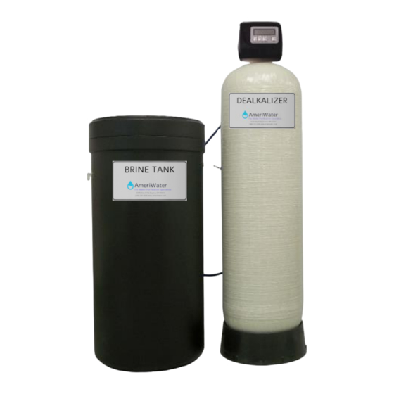
- Page 1 AmeriWater Operation & Maintenance Manual The Water Purification Specialists Dealkalizer Clack Model V125DTH Medical Series 3345 Stop 8 Rd, Dayton, OH 45414 | 800 535 5585 | www.ameriwater.com 98-0181 Rev B Manufactured With Pride in The USA...
-
Page 3: Table Of Contents
Table of Contents INTRODUCTION & WARNINGS ................2 MEDICAL SERIES SYSTEM SPECIFICATIONS ............3 Dealkalizer ....................3 DEALKALIZER OPERATION SUMMARY ..............4 Description ....................4 How It Works ....................4 Flow Diagrams ....................5 Monitoring..................... 8 SYSTEM INSTALLATION ..................9 Installation Requirements ................ -
Page 4: Introduction & Warnings
Your Water Purification Equipment was thoroughly tested and in excellent condition when it was shipped to you. However, because damage during shipment is possible, please unpack and carefully inspect as soon as you receive it. Please notify AmeriWater immediately if any problems or shipping damages are identified. -
Page 5: Medical Series System Specifications
MEDICAL SERIES SYSTEM SPECIFICATIONS 2.1 Dealkalizer FEATURES: A full flow 1¼” valve. The control valve utilizes the time proven piston-seal-spacer technology for durable, maintenance free service. All plastic construction will not corrode. Programmable electronic controller is flexible for all conditions. All times can be set to the minute. -
Page 6: Dealkalizer Operation Summary
DEALKALIZER OPERATION SUMMARY 3.1 Description The Dealkalizer reduces the alkalinity in the feed water present as bicarbonate, carbonate, or hydroxide to prevent high pH water from interfering with the performance of the carbon filtration and the reverse osmosis system. 3.2 How It Works Dealkalizers are basically anion water softeners (standard softeners use cation resin rather than anion resin). -
Page 7: Flow Diagrams
3.3 Flow Diagrams 98-0181 Rev B... - Page 8 98-0181 Rev B...
- Page 9 98-0181 Rev B...
-
Page 10: Monitoring
3.4 Monitoring 1. Verify at the beginning of each day that the control head timer is set to the correct time and correct day, record that this verification was done. This prevents the system from inadvertently regenerating during clinical operation, which would cause the RO to shut down via the interlock mechanism. -
Page 11: System Installation
SYSTEM INSTALLATION 4.1 Installation Requirements Water Pressure A minimum 20 pounds per square inch of inlet water pressure, is required for the regeneration valve to effectively operate Electrical Facilities An uninterrupted alternating current (A/C) supply is required. Make sure: Voltage supply is compatible with unit before installation. -
Page 12: Installation Instructions
4.2 Installation Instructions 1. Always install devices as shown on the AmeriWater Piping and Instrumentation Drawing (P&ID) provided with the water purification system. Failure to do so may adulterate the marketing clearance on the device and void all AmeriWater warranties. - Page 13 12. Connect all plumbing in accordance to your local plumbing codes. The dealkalizer should be installed using the appropriate AmeriWater Bypass Header. This allows the device to be bypassed for service. 13. Make plumbing connections to the Clack V125DTH valve head.
- Page 14 Clack V125DTH Models Model W x D x H Brine Tank D X H Anion Resin(32540628) Small Gravel(33-0050) 0095106 10" x 17" x 62" 18" x 40" 1.5 CU FT .5 CU FT 0095107 14" x 17" x 55" 18" x 40"...
-
Page 15: Start-Up Instructions
4.3 Start-up Instructions 1. Completely program the control valve or verify it has been programmed correctly [ The "Fill" cycle has to be programmed to support the brine tank testing]. 2. Perform these steps to flush pipe cutting debris & other debris from the piping prior to putting water into the control valve and vessel [Debris can enter the control valve and cause an easily avoided failure ]. - Page 16 b) On the control valve, cycle the valve into the "Rinse" position. Once the control valve is in the "Rinse" position, unplug the control valve from the 120‐ Volt receptacle [Rinse position is to send the water thru the resin and out the drain, unplugging the control valve allows for unlimited time to complete the color throw rinseout].
- Page 17 a difference is noted from the previously recorded measurement [Disconnecting the brine line and checking for vacuum will not verify the air check assembly in the brine well is functioning]. g) Allow the water to continue being suctioned out until the level drops to about the midpoint of the air check screened intake area.
-
Page 18: Programming Charts And System Programming
Height) Cubic Feet Resin Injector 1.23 Size (GPM) Backwash Flow Control Table 1. Dealkalizers Clack V125DTH Programming Step Description Instructions Enter into First Tier programming Press NEXT and Down Arrow simultaneously for 5 seconds and release. Choose Softening Choose SOFTENING using ▲... - Page 19 Set the 7 day using ▲ or ▼. Select 7 Day timer Set Relay Operation (OFF) Set Relay Operation using ▲ or ▼. To enter Installer Display (Second Tier Press NEXT and UP Arrow programming) simultaneously for 5 seconds and release. Set Current Day of the Week Set the current day of the Set to Desired Day:D1 = Sun, D2 =...
-
Page 20: Troubleshooting
TROUBLESHOOTING Problem Possible Cause Solution 1. No Display on PC Board a. No power at electric outlet a. Repair outlet or use working outlet b. Control valve Power Adapter b. Plug Power Adapter into outlet or not plugged into outlet or power connect power cord end to PC Board cord end not connected to PC connection... - Page 21 connector METER f. Defective meter f. Replace meter g. Defective PC Board g. Replace PC Board 8. Hard or untreated water is a. Bypass valve is open or a. Fully close bypass valve or replace being delivered faulty b. Check program settings or diagnostics b.
- Page 22 13. Water running to drain a. Power outage during a. Upon power being restored control will regeneration finish the remaining regeneration time. b. Damaged seal/ stack Reset time of day assembly b. Replace seal/ stack assembly c. Piston assembly failure c.
- Page 23 16. E3, Err – 1003, Err – 103 = a. Motor failure during a a. Check motor connections then Press Control valve motor ran too regeneration NEXT and REGEN buttons for 3 seconds to long and was unable to find the b.
- Page 24 19. Err – 1007, Err – 107, Err - a. Foreign material is lodged in a. Open up MAV/ NHBP valve and check 117 = MAV/ SEPS/ NHBP/ AUX MAV/ NHBP valve piston and seal/ stack assembly for foreign MAV valve motor ran too short b.
-
Page 25: Parts Lists And Repair Diagrams
NUMBER CLACK,SPACER STACK 050-0319 ASSY,V125DTH CLACK,PISTON ASSEMBLY, 050-0320 DOWNFLOW,V125DTH CLACK,WS1 REGENERANT 050-0321 PISTON,V125DTH O-RING, 228,CLACK V125DTH, 050-0308 KIT FOR ALL O-RINGS IS 911-50- 0385 O-RING, 337,CLACK V125DTH, 050-0310 KIT FOR ALL O-RINGS IS 911-50- 0385 O-RING, 219,CLACK V125DTH, 050-0312 KIT FOR ALL O-RINGS IS 911-50- 0385 7. - Page 26 DRAWING ORDER NO. DESCRIPTION QUANTITY NUMBER 050-0317 CLACK,INJECTOR CAP,V125DTH O-RING, 135,CLACK V125DTH, KIT FOR ALL 050-0309 O-RINGS IS 911-50-0385 050-0318 CLACK,INJECTOR SCREEN CAGE,V125DTH 50-0411 CLACK,INJECTOR,PLUG,V125DTH CLACK,INJECTOR,V125DTH,BLUE,0.9GPM 50-0386 TOTAL FLOW (10x54 Tank) CLACK,INJECTOR,V125DTH,GREEN,1.23GPM 50-0387 TOTAL FLOW (14x47,14x65,16x65 Tanks) CLACK,INJECTOR,V125DTH,ORANGE,1.7GPM 50-0388 TOTAL FLOW (18x65 Tank)
- Page 27 REFILL,PLUG,V125DTH CLACK,ELBOW LOCKING 050-0322 CLIP,REFILL FLOW CONTROL ASSY,V125DTH CLACK,ELBOW 3/8" 050-0323 LIQUIFIT,REFILL FLOW CONTROL ASSY,V125DTH O-RING, 019,CLACK V125DTH, KIT 050-0314 FOR ALL O-RINGS IS 911-50-0385 CLACK,REFILL FLOW CONTROL 050-0324 RETAINER ASSY,V125DTH ELBOW,.38 LIQUIFIT ASSY, WITH 050-0316 REFILL FLOW CONTROL 7. NOT...
- Page 28 DRAWING ORDER DESCRIPTION QUANTITY NUMBER CLACK,DRAIN LINE ASSY,3/4 1. NOT SHOWN 050-0326 INCH,V125DTH CLACK,DRAIN LINE ASSY,1 2. NOT SHOWN 050-0327 INCH,V125DTH CLACK,DRAIN LINE FLOW 3. NOT SHOWN 50-0392 CONTROL,2.7GPM,V125DTH (10x54 Tank) CLACK,DRAIN LINE FLOW 4. NOT SHOWN 50-0393 CONTROL,5.3GPM,V125DTH (14x47, 14x65 Tank) CLACK,DRAIN LINE FLOW 5.
- Page 29 DRAWING ORDER DESCRIPTION QUANTITY NUMBER CLACK,WRENCH,REPAIR AND BREAK 0403 APART,V125DTH 98-0181 Rev B...
-
Page 30: Pre-Treatment Lockout
PRE-TREATMENT LOCKOUT 98-0181 Rev B... - Page 31 98-0181 Rev B...
- Page 32 Polyvinyl Chloride (PVC). The AmeriWater system you have purchased may contain PVC or stainless steel parts. While warnings are only required in the State of California, AmeriWater has initiated the use of Prop 65 labeling for all products to ensure compliance with California regulations. Please note that the above warning does not necessarily mean that the product that you have purchased is unsafe.
Need help?
Do you have a question about the Clack V125DTH and is the answer not in the manual?
Questions and answers