Table of Contents
Troubleshooting

Related Manuals for AmeriWater MRO3


Summary of Contents for AmeriWater MRO3
- Page 1 MRO3 & MRO4 OPERATION & MAINTENANCE MANUAL FOR MODELS MRO3 AND MRO4 Manufactured With Pride In The USA www.ameriwater.com • 800-535-5585 AmeriWater • 3345 Stop 8 Rd. • Dayton, OH 45414 MRO 3 and MRO4 MANUAL 98-0140 Rev. F...
-
Page 2: Table Of Contents
TEMPERATURE CORRECTED MRO PRODUCTION RATES ..................... 4 SECTION 3 COMPONENTS AND SCHEMATICS .................. 5 EXTERNAL FRONT VIEW .............................. 5 INTERNAL REAR VIEW ..............................7 ELECTRICAL DIAGRAM, MRO3 & MRO4 ........................9 SECTION 4 MRO STARTUP & OPERATION ..................11 CAUTION ................................... 11 SAFETY FEATURES ..............................13 INITIAL STARTUP ............................... - Page 3 SECTION 10 WARRANTY ....................... 48 SECTION 11 MRO3 & 4 SPARE PARTS LISTING ................49 11.1 ROUTINE REPLACEMENT ITEMS (NON-DURABLE COMPONENTS) ................51 ATTACHMENT 1 - SUMMARY DISINFECTION PROCEDURE...
-
Page 4: Section 1 General Information
Your MRO system was thoroughly tested and in excellent condition when it was shipped to you. However, because damage during shipment is possible, please unpack and carefully ® inspect the MRO as soon as you receive it. Please notify AmeriWater if any problems are encountered. -
Page 5: Cautionary Symbols
CAUTIONARY SYMBOLS Caution, risk of electrical shock! Attention, risque de choc électrique! Open by qualified service personnel only! Ouverture par le personnel qualifié seulement! Refer to this Operation and Maintenance Manual for instructions and safety considerations. Référez-vous au manuel des Opérations et Entretien pour instructions et mesures de sécurité. -
Page 6: Section 2 Technical Information
Water pressure to dialysis machine Controlled by Loop return relief valve. Maximum output of product water MRO3 - 4200 GPD (15,897 LPD) @ 77°F (25°C), TDS<1000 ppm of MRO4 - 5600 GPD (21,196 LPD) NaCl, & pump pressure of 150 psi. -
Page 7: Mro Output Water Quality
The physician in charge of dialysis has the ultimate responsibility for selecting the maximum allowable levels of chemical contaminants in the water, and, also, is responsible for monitoring the water. The AmeriWater MRO System is designed to produce water that meets or exceeds ANSI/AAMI RD62 requirements. -
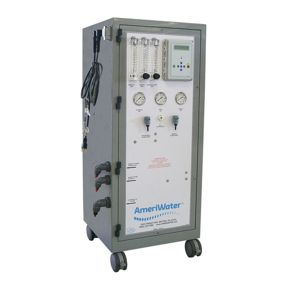
Page 8: Section 3 Components And Schematics
SECTION 3 COMPONENTS AND SCHEMATICS EXTERNAL FRONT VIEW MRO 3 & 4 MANUAL 98-0140 Rev. F... - Page 9 IDENTIFICATION OF COMPONENTS (EXTERNAL FRONT VIEW) PRODUCT GPM: Rotameter that measures the flow of the Product Water For Dialysis in gallons per minute (GPM). SIDE ENTRY HOOD: External wire installation for float level switches, pretreat lockout and RO alarm relay connectors. REJECT GPM WITH VALVE: Rotameter with valve to control the flow of the Reject water to drain, in gallons per minute (GPM).
-
Page 10: Internal Rear View
INTERNAL REAR VIEW MRO 3 & 4 MANUAL 98-0140 Rev. F... - Page 11 (CIP) switch is placed to the ON position, all MRO fail-safe modes are disabled for low-pressure membrane cleaning with the optional AmeriWater Clean In Place system (P/N 00CIP1). The controller will display a warning that the CIP mode is active.
-
Page 12: Electrical Diagram, Mro3 & Mro4
ELECTRICAL DIAGRAM, MRO3 & MRO4 MRO 3 & 4 MANUAL 98-0140 Rev. F... - Page 13 FLUID DIAGRAM, MRO3 & MRO4 MRO 3 & 4 MANUAL 98-0140 Rev. F...
-
Page 14: Section 4 Mro Startup & Operation
SECTION 4 MRO STARTUP & OPERATION CAUTION NOTE: This entire Operations Manual should be read before operating or servicing the MRO system. The Operations Manual should then be kept near the system and used as a reference and troubleshooting guide. WARNING: This Reverse Osmosis System (RO) contains a preservative solution to prevent microbiological growth and freezing. - Page 15 CAUTION: Mixing chlorine and hydrogen peroxide/peroxyacetic acid causes a toxic chemical reaction. Never allow them to mix! Do not use chlorine to disinfect the system! Use only the exact amount of PAA disinfectant solution and in proper dilution during disinfection of the system. It is important to test for PAA in the Product Water For Dialysis after rinsing during disinfection of the system.
-
Page 16: Safety Features
WHEN NO STORAGE TANK IS BEING USED. WARNING: However, when the MRO3 or 4 is connected to a storage tank, the Product water will divert to drain as long as the Product Water is out of specification with no water going to the Storage Tank. The poor quality alarm for the MRO will sound, but the water already in the storage tank can continue to be used from the tank. -
Page 17: Initial Startup
INITIAL STARTUP WARNING: This Reverse Osmosis System (RO) contains a preservative solution to prevent microbiological growth and freezing. Discard all product water for at least two hours of operation before placing the RO in service. 1. Lock the two front casters so that the MRO will remain stationary during startup. 2. - Page 18 “twist lock” high voltage polarized receptacle that has been installed by a qualified electrician. For 3 phase applications, the 3-wire connections must be verified to give the correct rotation on the MRO pump. If not, specified pressure cannot be obtained, and the pump will quickly overheat. 12.
-
Page 19: System Shutdown
SYSTEM SHUTDOWN Ordinarily, an MRO3 or 4 is connected to a water use system that is used continually or very frequently. Therefore, frequent shutting down is not necessary. Typically, the MRO is connected to a Direct Feed Loop or Storage Tank of a Central System. If so, the MRO should be cycled using the “Membrane Flush”... -
Page 20: Section 5 Disinfecting The System
As a general guideline, AmeriWater recommends that the system should be disinfected at least monthly. In addition, AmeriWater recommends that the system be disinfected if it has not been: used for 24 hours or flushed at least every 8 hours. - Page 21 WARNING: The disinfection mode will allow PAA to flow through the PRODUCT WATER hose. This is to allow disinfection of the hoses and the connected “small” direct-feed water loop. If the “small” direct-feed water loop is to be disinfected with the MRO, fill and draw the PAA solution container at least twice and up to 5 times to allow sufficient volume into the loop for complete disinfection.
- Page 22 Press and hold the ENTER key to turn on the Disinfect Draw function and THE DISPLAY WILL READ DISINFECT ENABLED DRAW. Adjust the REJECT flow control knob so that the PAA will be drawn into the MRO in about 2 minutes. (Figure 5.1) The REJECT flow amount will have to be determined the first time the PAA is drawn in, and noted so that it will empty the container in about 2 minutes.
- Page 23 19b. If the MRO is connected to a small direct-feed loop during disinfection, then the entire loop must test positive for PAA throughout the loop. Using a fresh test strip at each dialysis machine water outlet, test the water. The result must be at least 0.5% (250 ppm).
- Page 24 Press and hold the LEFT ARROW key and then, press the RIGHT ARROW key. This will access the DISINFECT MODE. The controller display will show DISINFECT ENABLED and the keys can be released. Press and hold the ENTER key to turn on the Disinfect Draw function and THE DISPLAY WILL READ DISINFECT ENABLED DRAW.
- Page 25 (no color change) to ensure that there is less than 3 PPM of PAA disinfecting solution remaining in the entire water system. AmeriWater recommends using Renal Check PX Test Strips (P/N 97PX20501) Record the Stop time on the Log to have a record of how long it takes for the disinfecting solution to completely rinse out.
-
Page 26: Disinfecting An Mro Connected To A "Large" Loop
This is good for cleaning, but great care must be exercised for disinfection. To clean an MRO, an AmeriWater CIP2 cleaning system is required to be connected to the MRO. Place the MRO in “STANDBY”, turn off the water supply and disconnect the MRO feed water inlet hose from the Product Recovery unit, and connect it to the CIP2 pump outlet. -
Page 27: A Word About Hydrogen Peroxide/Peroxyacetic Acid
A WORD ABOUT HYDROGEN PEROXIDE/PEROXYACETIC ACID Do not use hydrogen peroxide/peroxyacetic acid concentrate (PAA) after the expiration date. Using outdated PAA concentrate may cause incomplete disinfection. PAA loses effectiveness if not kept out of direct sunlight and/or the cap is not tightly sealed. Using ineffective disinfecting solution will cause incomplete disinfection. -
Page 28: Membrane Flush Feature (Auto Flush)
The MEMBRANE FLUSH FEATURE is the preferred means for minimizing bacterial growth for the MRO3 or MRO4 during periods of low water usage. Ordinarily these sizes of MRO are connected to a loop or storage tank only having 1-2 days of non-use when dialysis procedures are not being carried out. -
Page 29: Section 6 Mro Controller
SECTION 6 MRO CONTROLLER FRONT PANEL CONTROLS AND INDICATORS DISPLAY FIGURE 6.1 DISPLAY - Shows status of system. ALARM LAMP - Flashes when fault causes an RO system shut down. On steady when a Setpoint is exceeded that does not cause an RO system shut down. -
Page 30: Controller Operation
CONTROLLER OPERATION GENERAL OPERATION The unit has 2 modes of operation, a standby mode and an operating mode that are controlled by the POWER key. In the standby mode, the unit is effectively off. All outputs are turned off and the display shows STANDBY. In the operating mode, the unit operates automatically. - Page 31 The current water temperature is shown on the bottom line to the right of operating hours. When the unit is in STANDBY due to a shut down condition, the reading is replaced with ‘---‘. WARNING MESSAGES Warning messages are also shown on the second line. If any warnings are active, the active warnings will alternate with the normal displays for the bottom line.
- Page 32 AUTO RESET If a pressure fault shut down occurs and the Auto Reset Setpoint is programmed to 0, the unit will remain shut down until manually reset. If the Auto Reset Setpoint is programmed to a value greater than 0, the unit will automatically clear the pressure fault and attempt to restart after this delay times out.
-
Page 33: Controller Adjustments
It may be necessary to periodically calibrate the Conductivity. If the controller should require calibration, follow the instructions below. Please contact AmeriWater at 800/535-5585 or 937/461-8833 if you have any questions regarding the procedure. - Page 34 FIGURE 6.2 MRO 3 & 4 MANUAL 98-0140 Rev. F...
- Page 35 FIGURE 6.3 MRO 3 & 4 MANUAL 98-0140 Rev. F...
-
Page 36: Standard Setpoints
STANDARD SETPOINTS FACTORY SETPOINT DESCRIPTION RANGE SETTING When this value is met or exceeded, the Based on 0-999 TDS/Cond Limit alarm lamp will light and high TDS/Cond will water µS or PPM* show on the display. To disable, set to 0. analysis. - Page 37 FACTORY SETPOINT DESCRIPTION RANGE SETTING The interval between flush cycles. Only valid 0-99 Flush Interval with operation hour, elapsed time or off flush minutes types. Selects if the inlet and RO pump relays Flush Mode operate during flush. If the current operating hours exceed this 0-65000 Maximum Hours limit, the operating hours warning will occur.
-
Page 38: To Display Or Change Setpoints
TO DISPLAY OR CHANGE SETPOINTS NOTE: Please contact your AmeriWater representative prior to changing set points. 1. Refer to Figure 6.1 for the location of the keys used to display or change the Setpoints and Figure 6.2 for the location of the write protect jumper, J3. For the unit to be able to accept a change in a Setpoint, the shorting jumper must be in the WRITE PROTECT OFF position (center and left pins). -
Page 39: Section 7 External Wire Installation
SECTION 7 EXTERNAL WIRE INSTALLATION FLOAT LEVEL SWITCHES, PRETREAT LOCKOUT & RO ALARM RELAY CONNECTORS Remove the side entry hood by disengaging the lock and pulling down. Loosen 4 retaining screws from outer shroud and remove inner terminals. Loosen the nut and run the float switch wires through the outer housing. Connect the High Tank float wires to contacts 1 &... -
Page 40: Section 8 Maintenance
NOTE: All major components for the Portable MRO are stocked for emergency shipment. MAINTAINING THE SYSTEM 1. AmeriWater has provided a Startup Log for the MRO system. This must be filled out completely each time the system is used. The recorded information may be useful in troubleshooting problems encountered with the MRO. -
Page 41: Pt401 Anti-Scalant
PT401 ANTI-SCALANT Smaller AmeriWater MRO products have the PT401 antiscalant system equipped as an option. The larger units, MRO3 & 4 ordinarily have a complete water pre-treatment system (backwashing particulate filter, backwashing carbon filter, and water softener) installed ahead of the MRO. This eliminates the need for the PT401 anti-scalant system within the MRO, and is not a point of discussion in this manual. - Page 42 Remove the white snap ring from the inlet end of the housing and remove the end cap by pulling straight out. NOTE: Remove the endcap only from the inlet end of the housing. Inserting a membrane from the discharge end will damage the membrane’s brine seal. Remove the old membrane.
-
Page 43: Ameriwater Clean In Place (Cip)
WARNING: If the product water conductivity does not come out of alarm, do not use the system! Continue rinsing, or call AmeriWater for guidance. AMERIWATER CLEAN IN PLACE (CIP) 1. Move the CLEAN IN PLACE SWITCH (inside the MRO on the back of the controller) to the ON position. -
Page 44: Section 9 Troubleshooting And Repair
MRO system. To assist you in quickly restoring your system into service, AmeriWater will send your replacement part out immediately and check your bad part when it comes in to verify if it is covered under your equipment warranty. - Page 45 PROBLEM POSSIBLE CAUSE CORRECTIVE ACTION Disinfect cycle will not Disinfect Solenoid Valve not Test solenoid valve (Section operate when holding the operating 9.5). Replace the valve if it ENTER key (cont’d) fails (Section 9.6). Pump making excessive Low pressure or flow rate Check the inlet gauge PSI noise feeding the MRO...
- Page 46 PROBLEM POSSIBLE CAUSE CORRECTIVE ACTION Low product flow rate Low pressure feeding Verify that the incoming tap membrane water supply is fully open. The pressure on the inlet gauge should be > 20 PSI when the MRO is operating. Low pump PSI Pump should be operating at 175 –...
-
Page 47: Controller Troubleshooting
When disconnecting or connecting any board or accessory, be sure power is unplugged. Before contacting AmeriWater for technical help, verify the programming of all Setpoints, check the display and check the status of all lights and indicators. The more information available when you contact us, the easier it will be to determine the source of the problem. - Page 48 PROBLEM INVESTIGATION CORRECTIVE ACTION RO Pump Will Not Operate Is the system in standby? (Cont.) If no, are any shut down conditions active? If no, is the RO LED, DS6 If no, replace the board. lit? If no, replace the board. If yes, with a voltmeter, verify if there is power on the RO If yes, check the pump and...
-
Page 49: Pump Repair
PUMP REPAIR The following procedures are instructions for removing the pump from the unit. Before replacing the pump, be sure the pump’s thermal overload has not tripped. Allow the pump to sit at least 5 minutes to allow it to reset, then try to re-start the pump. 1. -
Page 50: Solenoid Test Procedure
SOLENOID TEST PROCEDURE Feed Solenoid 1. With the MRO Off, turn the Incoming Tap Water supply on. If there is water flowing to the drain, the solenoid has failed open. 2. Turn on the MRO, with the Incoming Tap Water supply still on. If there is no flow to the drain, the solenoid has failed closed. - Page 51 8. Install per the kit installation instructions. 9. Connect the wire harness to the valve. 10. Replace the membrane(s), and pump. 11. To verify that the solenoid valve is installed correctly, follow the Solenoid Test Procedures in Section 9.5. SECTION 10 WARRANTY The buyer has a one year warranty on all equipment and parts, excluding non-durable components (e.g., RO membrane, carbon, PT401, and micron prefilter);...
- Page 52 SECTION 11 MRO3 & 4 SPARE PARTS LISTING MRO 3 & 4 MANUAL 98-0140 Rev. F...
- Page 53 MRO 3 & 4 MANUAL 98-0140 Rev. F...
- Page 54 97CM20201 For Measuring Low Level Chlorine/Chloramine LAL Endotoxin Testing, Exact results in just a few days AAMI AAMI Chemical Analysis, Results within one week *Call AmeriWater or your AmeriWater distributor for pricing. MRO 3 & 4 MANUAL 98-0140 Rev. F...
Need help?
Do you have a question about the MRO3 and is the answer not in the manual?
Questions and answers
The auto flush settings does not come on. Was activated a few days ago but now, it refuses to activate. I re-entered ghe recommended settings, followed each step outlined in the manual, and no result
The auto flush setting is not activating on the AmeriWater MRO3 because the Membrane Flush feature is disabled by default from the factory. To activate it, specific setpoints must be configured on the MRO controller, including Flush Type, Flush Time, Flush Interval, and Flush Mode.
This answer is automatically generated