
Related Manuals for AmeriWater MRO3Z


Summary of Contents for AmeriWater MRO3Z
- Page 1 MROZ OPERATION & MAINTENANCE MANUAL Manufactured With Pride In The USA www.ameriwater.com • 800-535-5585 AmeriWater • 3345 Stop 8 Rd. • Dayton, OH 45414 98-0155 Rev. C...
- Page 2 98-0155 Rev. C...
- Page 3 CAUTIONARY SYMBOLS Caution, risk of electrical shock! Attention, risque de choc électrique! Open by qualified service personnel only! Ouverture par le personnel qualifié seulement! Refer to this Operation and Maintenance Manual for instructions and safety considerations. Référez-vous au manuel des Opérations et Entretien pour instructions et mesures de sécurité.
-
Page 4: Table Of Contents
TABLE OF CONTENTS PAGE GENERAL INFORMATION.................... 1 1.1 INTRODUCTION ................................1 1.2 RESTRICTION ON USE ..............................1 1.3 INDICATIONS FOR USE ..............................2 TECHNICAL INFORMATION ..................3 2.1 SPECIFICATIONS ................................3 2.2 MROZ OUTPUT WATER QUALITY ........................... 5 2.3 ENVIRONMENTAL/TRANSPORT CONDITIONS EXPECTED ....................6 COMPONENTS AND SCHEMATICS ................ - Page 5 98-0155 Rev. C...
-
Page 6: General Information
It must be preceded by pre-treatment devices, and may need to be followed by post-treatment devices as well to meet current AAMI and Federal (U.S.) standards. This Operation Manual was written for the MRO3Z, MRO4Z, MRO5Z, MRO6Z, MRO7Z and MRO8Z models. -
Page 7: Indications For Use
The AmeriWater MROZ Reverse Osmosis System is a water treatment device intended for use in hemodialysis applications. It is intended to be used as a component in the AmeriWater Water Purification System (K991519), and is intended to purify potable water for use in making dialysate for hemodialysis and to meet current AAMI and Federal (U.S.) -
Page 8: Technical Information
100 PSI Maximum 200 PSI Water pressure to dialysis machine Controlled by Loop return relief valve. MRO3Z – 5513 TO 8,750 GPD (20,869 TO 33,122 LPD) MRO4Z – 7245 TO 11,500 GPD (27,425 TO 43,532 LPD) Maximum output of product water MRO5Z –... - Page 9 80” H x 32" W x 58" D Dimensions not Packaged 76”H x 30”W x 55”D MRO3Z 360 - 410 lbs. / 285 lbs. MRO4Z 390 - 440 lbs. / 320 lbs. MRO5Z 420 - 470 lbs. / 355 lbs.
-
Page 10: Mroz Output Water Quality
The physician in charge of dialysis has the ultimate responsibility for selecting the maximum allowable levels of chemical contaminants in the water, and, also, is responsible for monitoring the water. The AmeriWater MROZ System is designed to produce water that meets or exceeds ANSI/AAMI requirements. -
Page 11: Environmental/Transport Conditions Expected
2.3 ENVIRONMENTAL/TRANSPORT CONDITIONS EXPECTED ENVIRONMENTAL CONDITIONS ANTICIPATED This device is intended to be used under the following conditions: Indoor use; Altitude up to 2000 m; 6562 feet Temperature between 5°C and 40°C; 41°F and 104°F Maximum relative humidity 80% for temperatures up to 31°C (87.8°F) decreasing linearly to 50% relative humidity at 40°C (104°F) MAINS supply voltage fluctuations up to + 10% of the nominal voltage;... -
Page 12: Components And Schematics
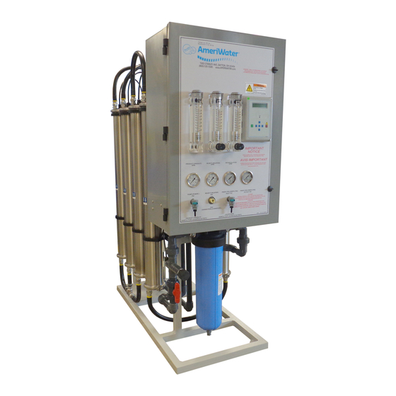
COMPONENTS AND SCHEMATICS 3.1 EXTERNAL FRONT VIEW MRO3Z THRU MRO6Z CONFIGURATION SHOWN, MRO7Z & MRO8Z MODELS HAVE AN EXTERNALLY MOUNTED PRE-FILTER CARTRIDGE ASSEMBLY. Figure 3.1 98-0155 Rev. C... - Page 13 MRO7Z and MRO8Z CONFIGURATION SHOWN BELOW Figure 3.2 98-0155 Rev. C...
- Page 14 IDENTIFICATION OF COMPONENTS (EXTERNAL FRONT VIEW) PRODUCT GPM: Rotameter that measures the flow of the Product Water for Dialysis in gallons per minute (GPM). SIDE ENTRY HOOD: External wire installation for float level switches, pretreat lockout and RO alarm relay connectors; (See Section 7). REJECT GPM WITH VALVE: Rotameter with valve to control the flow of the Reject water to drain, in gallons per minute (GPM).
-
Page 15: Internal Cabinet, Top And Side View
3.2 INTERNAL CABINET, TOP AND SIDE VIEW Figure 3.3 98-0155 Rev. C... -
Page 16: Internal Cabinet, Top And Side View Cont
3.3 INTERNAL CABINET, TOP AND SIDE VIEW CONT. Figure 3.4 98-0155 Rev. C... - Page 17 (CIP) switch is placed to the ON position, all MROZ fail-safe modes are disabled for low-pressure membrane cleaning with the optional AmeriWater Clean In Place system (P/N 00CIP2). The controller will display a warning that the CIP mode is active.
-
Page 18: Electrical Diagram And Field Wiring
3.4 ELECTRICAL DIAGRAM AND FIELD WIRING Figure 98-0155 Rev. C... - Page 19 Figure 3.6 98-0155 Rev. C...
- Page 20 Figure 3.7 98-0155 Rev. C...
-
Page 21: Flow Diagrams
3.5 FLOW DIAGRAMS Figure 3.8 98-0155 Rev. C... - Page 22 Figure 3.9 98-0155 Rev. C...
- Page 23 Figure 3.10 98-0155 Rev. C...
- Page 24 Figure 3.11 98-0155 Rev. C...
- Page 25 Figure 3.12 98-0155 Rev. C...
- Page 26 Figure 3.13 98-0155 Rev. C...
-
Page 27: Mroz Startup & Operation
MROZ STARTUP & OPERATION 4.1 CAUTION The Operations Manual should then be kept near the system and used as a reference and troubleshooting guide. Follow all safety procedures for the facility and company for which all work is being performed. CAUTION: No person should attempt to operate or service the MROZ without Prior authorization or instruction from your medical facility director. - Page 28 5. Incoming water should be between 41° F and 90° F (5° C and 33° C). It is not recommended to use water at temperatures below 41° F (5° C) as it will reduce membrane performance significantly. Never use water warmer than 90° F (33° C). Use only the cold water supply unless using an automatic blending valve to get 77°...
- Page 29 14. With the RO Operating, adjust the valve on the Reject flowmeter until the flow rate is equal to the product flow rate of the RO. This will be 50% recovery. Operating the RO at higher recovery percentage may reduce the life span of the RO membranes. Recovery is calculated via the following equation: 100% = 15.
-
Page 30: Safety Features
4.2 SAFETY FEATURES The MROZ is equipped with several safety features for the benefit of both the user and the patient. They consist of the following: 1. Disinfection using (PAA) disinfecting solution instead of formaldehyde increases safety and avoids health risks associated with formaldehyde. PAA produces no harmful by- products or side effects, thus it is safer for patients. -
Page 31: Initial Startup
4.3 INITIAL STARTUP WARNING: This Reverse Osmosis System (RO) contains a preservative solution to prevent microbiological growth and freezing. Discard all product water for at least two hours of operation before placing the RO in service. 1. Secure the RO to the floor. 2. - Page 32 10. Plug the controller power cord into a dedicated hospital grade UL Listed 120-volt GFI receptacle that is capable of 125VAC, 20AMP, 2.5kVA, -35C TO 66C, 60HZ, 4 TO 6mA leakage. 11. Connection to a wall disconnect must be done by a qualified electrician. The wall disconnect must be of a UL Listed, lockable, 4X NEMA rated fusible box, capable of 240VAC, 30AMP, 31.18kVA (For the 208/230V models) and 600VAC, 30AMP, 31.18kVA (For the 460V models).
-
Page 33: System Shutdown
MROZ shall remain in OPERATION. When the “Flush” feature is active, the MROZ will cycle on some predetermine frequency to send the Product Water through the “Divert to Drain” feature of the MROZ to the drain. If the MROZ must be shut down for an extended period, contact Ameriwater for instructions. 98-0155 Rev. C... -
Page 34: Disinfecting The System
5.1 DISINFECTION PROCEDURE The MROZ system should be disinfected according to specifications of your medical facility director. As a general guideline, AmeriWater recommends that the system should be disinfected at least monthly. Be sure to refer to your facilities Start-Up Log. This will help you verify that all steps are performed and recorded to disinfect the system properly. - Page 35 Add 800 ml of 100% PAA disinfecting solution to the PAA Container, and fill with water to the red line (tap water or treated water may be used). Screw the cap assembly securely back onto the PAA container. Agitate the container in a circular motion for approximately 10 seconds. Connect the PAA tubing male fitting into the quick disconnect fitting that is mounted on the front of the cabinet of the MROZ (Figure 5.1).
- Page 36 b. Use another test strip at the PRODUCT WATER hose, the result must be at least 0.5% (250 ppm). c. If the desired levels are not reached, press and hold “ENTER” button to force disinfectant thru the hoses. Label the MROZ with appropriate WARNING signs (Example: “DO NOT USE / CONTAINS DISINFECTANT”).
- Page 37 (no color change) to ensure that there are NO traces of PAA disinfecting solution remaining in the entire water system. AmeriWater recommends using Renal Check PX Test Strips (P/N 97PX20501) Record the Stop time on the Startup Log to have a record of how long it takes for the disinfecting solution to completely rinse out.
-
Page 38: A Word About Hydrogen Peroxide/Peroxyacetic Acid
5.2 A WORD ABOUT HYDROGEN PEROXIDE/PEROXYACETIC ACID Do not use hydrogen peroxide/peroxyacetic acid concentrate (PAA) after the expiration date. Using outdated PAA may cause incomplete disinfection. PAA loses effectiveness if not kept out of direct sunlight and/or the cap is not tightly sealed. Using ineffective disinfecting solution will cause incomplete disinfection. -
Page 39: Membrane Flush Feature (Auto Flush)
5.3 MEMBRANE FLUSH FEATURE (AUTO FLUSH) The MRO3Z-MRO8Z sizes are connected to a loop or storage tank only having 1-2 days of non-use when dialysis procedures are not being carried out. The MEMBRANE FLUSH FEATURE is the preferred means for minimizing bacterial growth for the MRO3Z-MRO8Z during periods when dialysis procedures are not being carried out. -
Page 40: Mroz Controller
MROZ CONTROLLER 6.1 FRONT PANEL CONTROLS AND INDICATORS FIGURE 6.1 DISPLAY DISPLAY - Shows status of system. ALARM LAMP - Flashes when fault causes an RO system shut down. On steady when a Set point is exceeded that does not cause an RO system shut down. -
Page 41: Controller Operation
6.2 CONTROLLER OPERATION GENERAL OPERATION The unit has 2 modes of operation, a standby mode and an operating mode that are controlled by the POWER key. In the standby mode, the unit is effectively off. All outputs are turned off and the display shows STANDBY. In the operating mode, the unit operates automatically. - Page 42 CONDUCTIVITY The Conductivity is shown on the top line after the unit operating status. When the unit is in STANDBY, because of a shutdown condition, the reading is replaced with ‘----’. If the reading is over range, the reading is shown as ‘^^^^’ when in the OPERATE mode. OPERATING HOURS The current operating hours are shown on the bottom line.
- Page 43 TANK FULL (TF) RESTART The tank full restart is the delay before the MROZ unit starts when a tank full condition clears. This delay can be in minutes or in seconds. The tank full restart set point selects seconds or minutes.
-
Page 44: Controller Adjustments
It may be necessary to periodically calibrate the Conductivity. If the controller should require calibration, follow the instructions below. Please contact AmeriWater at 800/535-5585 or 937/461-8833 if you have any questions regarding the procedure. - Page 45 Feed Water Adjustment Potentiometer Product Water Adjustment Potentiometer FIGURE 6.2 98-0155 Rev. C...
- Page 46 FIGURE 6.3 98-0155 Rev. C...
-
Page 47: Standard Setpoints
6.4 STANDARD SETPOINTS FACTORY SETPOINT DESCRIPTION RANGE SETTING When this value is met or exceeded, the Based on 0-999 TDS/Cond Limit alarm lamp will light and high TDS/Cond will water µS or PPM* show on the display. To disable, set to 0. analysis. - Page 48 FACTORY SETPOINT DESCRIPTION RANGE SETTING The interval between flush cycles. Only 0-99 Flush Interval valid with operation hour, elapsed time or off minutes flush types. Selects if the inlet and RO pump relays Flush Mode operate during flush. If the current operating hours exceed this 0-65000 Maximum Hours limit, the operating hours warning will occur.
-
Page 49: To Display Or Change Setpoints
6.5 TO DISPLAY OR CHANGE SETPOINTS NOTE: Please contact your AmeriWater representative prior to changing set points. 1. Refer to Figure 6.1 for the location of the keys used to display or change the Setpoints and Figure 6.2 for the location of the write protect jumper, J3. For the unit to be able to accept a change in a Setpoint, the shorting jumper must be in the WRITE PROTECT OFF position (center and left pins). - Page 50 µS/cm, you may want to change out the resistor in the R10 position with a replacement resistor, provided by AmeriWater. This replacement resistor can be identified by its color bands (Blue-Grey-Red-Gold). Alternatively, if you have an ohm-meter, the original resistor can be identified by its resistance value of 2.7 kΩ;...
-
Page 51: External Wire Installation
EXTERNAL WIRE INSTALLATION FLOAT LEVEL SWITCHES, PRETREAT LOCKOUT & RO ALARM RELAY CONNECTORS Remove the side entry hood by disengaging the lock and pulling down. Loosen 4 retaining screws from outer shroud and remove inner terminals. Loosen the nut and run the float switch wires through the outer housing. Connect the High Tank float wires to contacts 1 &... -
Page 52: Maintenance
8.2 MEMBRANE MAINTENANCE INSTRUCTIONS MEMBRANE REPLACEMENT PROCEDURE MRO3Z-MRO8Z: Turn off the incoming tap water supply to the MRO3Z-MRO8Z and unplug the MRO3Z- MRO8Z from the GFI receptacle. (The following procedure will cause water to leak and spill – This could occur at different times during the procedure - You may get wet.) Follow all safety procedures for the facility and company for which all work is being performed. - Page 53 NOTE: The plastic compression fitting will remain with the tubing on which it was connected. Loosen the clamps that hold the membrane assembly to the RO frame. Remove the end caps from each end of the membrane by loosening the bolts that hold these in place.
- Page 54 Turn on the MROZ. The rinse out cycle is now complete, and the MROZ is ready for use. WARNING: If the product water conductivity does not come out of alarm, do not use the system! Continue rinsing, or call AmeriWater for guidance. 98-0155 Rev. C...
-
Page 55: Prefilter Replacement Instructions
Even after relieving the pressure from the system and filter assembly, the filter housings could be full of water. Use care to prevent spillage. 2. For models MRO3Z, MRO4Z, MRO5Z and MRO6Z; use the filter wrench to unscrew the filter housing. -
Page 56: Troubleshooting And Repair
To assist you in quickly restoring your system into service, AmeriWater will send your replacement part out immediately and check your bad part when it comes in to verify if it is covered under your equipment warranty. - Page 57 PROBLEM POSSIBLE CAUSE CORRECTIVE ACTION DISINFECT MODE has not Access DISINFECT MODE been accessed correctly. (see 5.1). Circuit board relay not Replace the controller circuit Disinfect cycle will not operating in DISINFECT board (see 9.2). operate when holding the MODE. ENTER key Disinfect Solenoid Valve not Test solenoid valve (Section...
- Page 58 The pressure on the prefilter gauges should be > 20 PSI when the MROZ is operating. Low pump PSI. Pump should be operating MRO3Z 100-140 PSI MRO4Z 100-160 PSI MRO5Z 100-160 PSI MRO6Z 100-160 PSI MRO7Z 100-180 PSI MRO8Z 100-200 PSI...
-
Page 59: Controller Troubleshooting Matrix
Follow all safety procedures for the facility and company for which all work is being performed. Before contacting AmeriWater for technical help, verify the programming of all Setpoints, check the display and check the status of all lights and indicators. The more information available when you contact us, the easier it will be to determine the source of the problem. - Page 60 PROBLEM INVESTIGATION CORRECTIVE ACTION Inlet Valve Will Not If yes, with a voltmeter, If yes, check the valve and Operate (Cont’d.) verify if there is power on wiring. the inlet terminals. Is there power? RO Pump Will Not Is the system in standby? Operate If no, are any shut down conditions active?
- Page 61 PROBLEM INVESTIGATION CORRECTIVE ACTION Incoming Conductivity Indicates incoming Turn the Write Protect off Reads “^^^^” conductivity is greater than by moving the Write Protect 1000 µS. chip in the controller to the off position. Then change the value of C2 Range to either 5 or 6.
-
Page 62: Pump Repair
9.3 PUMP REPAIR The following procedures are instructions for removing the pump from the unit. The MRO3Z-MRO6Z Series has a pump with a ¾ NPT throttle valve. The MRO7Z-MRO8Z Series has a pump with a 1 NPT throttle valve. Before replacing the pump, be sure the pump’s thermal overload has not tripped. - Page 63 8. Secure the cap to the housing with the plastic locking ring previously removed. 9. Clean the threads from the fittings that were previously removed. Apply a suitable thread sealant and install into the cap. 10. Insert the pump assembly and reconnect the pump to the frame using the unistrut clamps.
-
Page 64: Solenoid Test Procedure
9.5 SOLENOID TEST PROCEDURE Feed Solenoid 1. With the MROZ Off, turn the Incoming Tap Water supply on. If there is water flowing to the drain, the solenoid has failed open. 2. Turn on the MROZ, with the Incoming Tap Water supply still on. If there is no flow to the drain, the solenoid has failed closed. -
Page 65: Warranty Policy
12. To verify that the solenoid valve is installed correctly, follow the Solenoid Test Procedures in Section 9.5. 10.0 WARRANTY POLICY This product is covered under the standard AmeriWater warranty policy. For specific terms and conditions, please contact your AmeriWater Sales Representative. 98-0155 Rev. C... -
Page 66: Spare Parts Listing
WaterCheck 2 (6 Bottles of 100 Strips each) 97CM20201 For Measuring Low Level Chlorine/Chloramine LAL Endotoxin Testing, Exact results in just a few days AAMI AAMI Chemical Analysis, Results within one week *Call AmeriWater or your AmeriWater distributor for pricing. 98-0155 Rev. C... -
Page 67: Spare Parts Items
KIT,REPLACEMENT,PUMP,2HP,460V/3PH,15GPM,FOR MRO5Z404 R188-0057 KIT,REPLACEMENT,PUMP,3HP,208V/3PH,20GPM,FOR MRO6Z402 R188-0058 KIT,REPLACEMENT,PUMP,3HP,230V/3PH,20GPM,FOR MRO6Z403 R188-0059 KIT,REPLACEMENT,PUMP,3HP,460V/3PH,20GPM,FOR MRO6Z404 KIT,REPLACEMENT,PUMP,3HP,208V/3PH,30GPM, FOR MRO7Z402 & R188-0065 MRO8Z402 KIT,REPLACEMENT,PUMP,3HP,230V/3PH,30GPM, FOR MRO7Z403 & R188-0066 MRO8Z403 KIT,REPLACEMENT,PUMP,3HP,460V/3PH,30GPM, FOR MRO7Z404 & R188-0067 MRO8Z404 *Call AmeriWater or your AmeriWater distributor for pricing. 98-0155 Rev. C...
Need help?
Do you have a question about the MRO3Z and is the answer not in the manual?
Questions and answers