Sign In
Upload
Manuals
Brands
Nortel Manuals
Network Router
8010co
Nortel 8010co Manuals
Manuals and User Guides for Nortel 8010co. We have
3
Nortel 8010co manuals available for free PDF download: Installing And Maintaining, Installation Manual
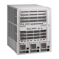
Nortel 8010co Installing And Maintaining (112 pages)
Brand:
Nortel
| Category:
Network Hardware
| Size: 2.54 MB
Table of Contents
Table of Contents
9
Preface
17
Before You Begin
17
Text Conventions
18
Hard-Copy Technical Manuals
18
How to Get Help
19
Passport 8000 Series Chassis Hardware Components
21
8010 Chassis
21
8010Co Chassis
22
8010 Chassis
23
Figure 1 8010Co Chassis and Components
23
Figure 2 8010 Chassis and Components
24
8006 Chassis
25
8003 Chassis
26
Figure 3 8006 Chassis and Components
26
Power Supplies
27
Figure 4 8003 Chassis and Components
27
Fan Trays
28
Table 1 Number of Fan Trays Installed each Chassis
28
Installing the 8010, 8006, and 8003 Chassis
29
Preparing to Install the 8010, 8006, and 8003 Chassis
29
Shipment Contents
30
Table 2 Chassis Shipping Accessories: 8010, 8006, 8003
30
Figure 5 Items in the 8010 Chassis Shipping Container
31
Figure 6 Items in the 8006 Chassis Shipping Container
32
Supplying Equipment
33
Management Console
33
Figure 7 Items in the 8003 Chassis Shipping Container
33
Cables
34
Hardware for Mounting the 8010, 8006, 8003 Chassis in an Equipment Rack
34
Site Requirements
34
Space Requirements
34
AC Input Electrical Requirements (8010, 8006 and 8003 Chassis)
35
DC Input Electrical Requirements (8010 and 8006 Chassis)
35
Table 3 Wall Receptacle Requirements for AC Power
35
Table 4 Electrical Requirements for the DC Model
35
Environmental Requirements
36
Installing the Chassis
36
Table 5 Environmental Requirements
36
Positioning the 8010, 8006, and 8003 Chassis on a Flat Surface
37
Mounting the 8010, 8006, and 8003 Chassis in an Equipment Rack
37
Table 6 Chassis Weight Including Components and Cables
37
Table 7 Maximum Number of Chassis in 7-Foot Rack
38
Figure 8 Positioning the Rack-Mounting Brackets: 8010 Chassis
39
Figure 9 Positioning the Rack-Mounting Brackets: 8006 Chassis
39
Figure 10 Positioning the Rack-Mounting Brackets: 8003 Chassis
39
Figure 11 Attaching the Rack-Mounting Brackets to the Chassis: 8010 Chassis
40
Figure 12 Attaching the Rack-Mounting Brackets to the Chassis: 8006 Chassis
40
Figure 13 Attaching the Rack-Mounting Brackets to the Chassis: 8003
40
Figure 14 Aligning the Rack-Mounting Brackets with the Equipment Rack
41
Table 8 Number of Rack Units to Allocate for Chassis
41
Figure 17 Installing the 8010 Chassis in an Equipment Rack
43
Figure 18 Installing the 8006 Chassis in an Equipment Rack
43
Figure 19 Installing the 8003 Chassis in an Equipment Rack
43
Installing the Cable Guides
44
Figure 20 Loosening the Rack-Mounting Screws: 8010 Chassis
44
Figure 21 Loosening the Rack-Mounting Screws: 8006 Chassis
44
Figure 22 Loosening the Rack-Mounting Screws: 8003 Chassis
45
Figure 23 Sliding the Cable Guide Onto the Screws
45
Figure 24 Sliding the Cable Guide Onto the Screws: 8003 Chassis
45
Figure 25 Securing the Cable Guide to the Chassis: 8010 Chassis
46
Figure 26 Securing the Cable Guide to the Chassis: 8006 Chassis
46
Figure 27 Securing the Cable Guide to the Chassis: 8003 Chassis
47
Installing the 8010Co Chassis
49
Preparing to Install the 8010Co Chassis
49
Shipment Contents
50
Table 9 8010Co Chassis Shipping Accessories
50
Figure 28 Accessories in the 8010Co Chassis Shipping Container
51
Supplying Equipment
52
Cables
52
Hardware for Mounting the Chassis in an Equipment Rack
52
Management Console
52
Site Requirements
53
Space Requirements
53
AC Input Electrical Requirements
53
Table 10 Wall Receptacle Requirements for AC Power
53
DC Input Electrical Requirements
54
Environmental Requirements
54
Table 11 DC Power Requirement for BIP
54
Table 12 Environmental Requirements
54
Installing the Chassis
55
Mounting the 8010Co Chassis in a Two-Post Rack
55
Figure 29 Two 8010Co Chassis with BIP in a Two-Post Rack
56
Mounting the 8010Co Chassis in a 19-Inch Rack
57
Figure 30 Location of Handles on the 8010Co Chassis
58
Figure 31 Installing the Installation Shelf in a 19-Inch Equipment Rack
59
Figure 32 Installing the 8010Co Chassis in a 19-Inch Two-Post Rack
60
Mounting the 8010Co Chassis in a Hendry Rack
61
Figure 33 Installing the Installation Shelf in a Hendry Rack
61
Figure 34 Removing the Mounting Rails from the 8010Co Chassis
62
Figure 35 Installing the Mounting Rails for a Hendry Rack
63
Figure 36 Location of Handles on 8010Co Chassis
64
Installing the Cable Management Brackets
65
Figure 37 Installing Cable Management Brackets
66
Grounding the 8010Co Chassis
67
Figure 38 Location of 8010Co Chassis Ground Studs
67
Figure 39 Chassis and DC Power Supply Grounding Example
69
Table 13 Item Description for Chassis and DC Power Supply Grounding
70
Figure 40 Chassis and AC Power Supply Grounding Example
71
Table 14 Item Description for Chassis and AC Power Supply Grounding
72
Connecting the Ground Cables to the Rack Grounding Strip
73
Figure 41 Rack Grounding Strip Example
73
Operating the Passport 8000 Series Switch
75
Turning the Passport 8000 Series Switch on and off
76
Turning DC Power Supplies on and off
76
Figure 42 DC Power Supply Power Switch
77
Turning AC Power Supplies on and off
78
Verifying a Successful Installation
79
Configuring the Chassis to Operate in E Mode or M Mode
80
Table 15 Boot Mode at Startup
80
Resetting the Passport 8000 Series Switch
81
Figure 43 Reset Button
81
Installing Removable Flash Memory Cards
82
Figure 44 Inserting a Removeable Flash Memory Card: 8010Co Chassis
82
Removing Removable Flash Memory Cards
83
Figure 46 Removing a Removeable Flash Memory Card: 8010Co Chassis
83
Protecting Memory Card Files
84
Figure 47 Removing a Removeable Flash Memory Card: 8010, 8006, 8003 Chassis
84
Replacing an Air Filter (8010Co Chassis Only)
85
Figure 48 Memory Card Read-Write Protect Switch
85
Removing and Inserting an Air Filter (8010Co Chassis Only)
86
Table 16 8010Co Air Filter Physical Specifications
86
Figure 49 Inserting an Air Filter into the 8010Co Chassis
87
Troubleshooting
88
LED Indications of Problems
88
Table 17 LED Problem Indicators
88
Apparent Module Failure
89
Module Failure Workaround 1
89
Module Failure Workaround 2
90
Failure to Get a Login Prompt from the Console Port
90
Figure 50 DCE/DTE Switch
90
Cable Connection Problems
91
10BASE-T Cables
91
100BASE-T and 1000BASE-T Cables
92
8100 Series Fiber MDA Cables
92
GBIC Cables
92
Autonegotiation Mode Problems for Passport 8100 Modules
92
Technical Specifications for the Passport 8000 Series Chassis
95
8010Co Chassis
95
Physical Specifications
96
Network Equipment Building Standard
96
Environmental Specifications
96
Maximum Airflow
97
8004AC Power Supply Specifications
97
8004DC Power Supply Specifications
97
System Power Specifications
98
International Regulatory Requirements
98
Electromagnetic Emissions
98
Electromagnetic Immunity
99
Safety Agency Certification
99
8010 Chassis
99
Physical Specifications
100
Environmental Specifications
100
8004AC-DC Power Supply Specifications
101
8004DC-DC Power Supply Specifications
101
System Power Specifications
102
International Regulatory Requirements
102
Electromagnetic Emissions
102
Electromagnetic Immunity
103
Safety Agency Certification
103
8006 Chassis
103
Physical Specifications
104
Environmental Specifications
104
8004AC Power Supply Specifications
105
8004DC Power Supply Specifications
105
System Power Specifications
106
International Regulatory Requirements
106
Electromagnetic Emissions
106
Electromagnetic Immunity
107
Safety Agency Certification
107
8003 Chassis
107
Physical Specifications
108
Environmental Specifications
108
8003ACPS Power Supply Specifications
109
System Power Specifications
109
International Regulatory Requirements
109
Electromagnetic Emissions
110
Electromagnetic Immunity
110
Safety Agency Certification
110
Index
111
Advertisement
Nortel 8010co Installing And Maintaining (108 pages)
Ethernet Routing Switch
Brand:
Nortel
| Category:
Chassis
| Size: 2.14 MB
Table of Contents
Table of Contents
3
Contents
5
New in this Release
7
Other Changes
7
Air Filter
7
Bezel Modifications
7
Document Changes
7
Document Corrections
7
Part Numbers
7
Introduction
9
Regulatory Information
10
Chassis Installation Fundamentals
17
8010Co Chassis
17
8010 Chassis
19
8006 Chassis
21
8003 Chassis
23
Power Supplies
24
Fan Trays
25
Site Requirements
26
8010, 8006, and 8003 Chassis
26
8010Co Chassis
27
Hardware Requirements
28
8010, 8006, and 8003 Chassis
28
8010Co Chassis
32
Successful Installation Verification
34
8010, 8006, and 8003 Chassis Installation
37
Positioning the Chassis on a Flat Surface
37
Mounting the Chassis in an Equipment Rack
38
Installing the Cable Management Brackets
44
8010Co Chassis Installation
49
Mounting the Chassis in a Two-Post Rack
49
Mounting the Chassis in a Hendry Rack
53
Installing the Cable Management Brackets
57
Installing 8004DC Power Supplies with the BIP
59
Grounding the Chassis
59
Nortel Ethernet Routing Switch 8600
59
Switch Operations
67
Powering on DC Power Supplies
67
Powering on AC Power Supplies
69
Resetting the Switch
70
Installing Removable Flash Memory Cards
70
Removing Removable Flash Memory Cards
72
Protecting Memory Card Files
73
Troubleshooting
75
Navigation
75
LED Indications of Problems
75
Apparent Module Failure
76
Module Failure Workaround 1
77
Module Failure Workaround 2
77
Failure to Get a Login Prompt from the Console Port
77
Cable Connection Problems
78
10BASE-T Cables
78
100BASE-T and 1000BASE-T Cables
79
GBIC Cables
79
Common Procedures
81
Reducing the Chassis Weight
81
Part Numbers
83
Technical Specifications
85
Chassis Weight
85
Rack-Mount
86
Model 8003AC Power Supply
86
Model 8004AC Power Supply
87
Model 8005AC Power Supply
87
Model 8004DC Power Supply
88
Model 8005DC Power Supply
89
Component Input Power
90
Input Power Consumption Example: 8010 Chassis
90
8004AC Power Supply Example
91
8004DC Power Supply Example
92
Input Power Consumption Example: 8006 Chassis
92
8005AC Power Supply Example
93
8005DC Power Supply Example
93
8010Co Chassis
94
Physical Specifications
94
Network Equipment Building Standard
94
Environmental Specifications
95
Maximum Airflow
95
Nortel Ethernet Routing Switch 8600
95
Installing and Maintaining the Ethernet Routing Switch 8000 Series Chassis
95
NN46205-303 01.02 Standard
95
International Regulatory Requirements
95
8010 Chassis
96
Physical Specifications
96
Environmental Specifications
97
International Regulatory Requirements
97
8006 Chassis
99
Physical Specifications
99
Environmental Specifications
99
International Regulatory Requirements
100
8003 Chassis
101
Physical Specifications
101
Environmental Specifications
102
International Regulatory Requirements
102
Index
104
Nortel Ethernet Routing Switch
105
Nortel 8010co Installation Manual (82 pages)
Installing the Breaker Interface Panel for the Ethernet Routing Switch
Brand:
Nortel
| Category:
Network Router
| Size: 1.89 MB
Table of Contents
International Regulatory Statements of Conformity
2
Statement of Conditions
2
National Safety Statements of Compliance
4
Table of Contents
7
Before You Begin
15
Preface
15
How to Get Help
16
Getting Help from the Nortel Web Site
16
Getting Help over the Phone from a Nortel Solutions Center
17
Getting Help from a Specialist by Using an Express Routing Code
17
Getting Help through a Nortel Distributor or Reseller
17
Text Conventions
16
Chapter 1 Overview
19
Physical Description
19
Figure 1 Breaker Interface Panel
19
Front Panel
20
Shelf Circuit Breakers (Upper and Lower Shelves)
20
Figure 2 Front Panel Components
20
Figure 3 Shelf Circuit Breakers
21
Alarm Module Display Panel
22
Figure 4 Alarm Module Display Panel
22
Table 1 Alarm Module Display Leds
22
Front Panel Locking Screws
24
Back Panel
24
Shelf Alarm Connectors (Upper and Lower Shelves)
24
Figure 5 Back Panel Components
24
Figure 6 Shelf Alarm Connections (Upper and Lower Shelves)
25
Central Office Alarms
26
Figure 7 Configuring Multiple Bips to Aggregate Office Alarms
26
Power Terminal Block
27
Figure 8 Configuring Standalone Bips to Report Alarm Status
27
Figure 9 Power Terminal Block
28
Figure 10 Power and Grounding Example
29
Accessing the Alarm Module
30
Figure 11 Opening the Front Panel
30
Figure 12 Accessing the Alarm Module
31
Figure 13 Default Jumper Settings
31
Configuration Example
32
Figure 14 8010Co Chassis Configuration with BIP Option
32
Chapter 2 Installation
33
Preparing to Install the Breaker Interface Panel
33
Shipment Contents
34
Figure 15 Contents of the BIP Shipping Container
34
Additional Equipment
35
Mounting Hardware
35
DC Input Electrical Requirements
35
Table 2 DC Power Requirements
35
Installing the Breaker Interface Panel
36
Installing the Hardware
36
Figure 16 Removing the Plastic Back Cover from the BIP
37
Figure 17 Installing the BIP in the Rack
37
36 Chapter 36 36 Chapter 2 Installation
38
Connecting Cables to the Chassis Power Supplies
38
Figure 18 Removing the 8010Co Chassis Bottom 312096-A Bezel
39
Figure 19 Location of Power Supplies
40
Figure 20 Loosening the Power Supply Retaining Screws
41
Figure 21 Disconnecting the Power Supply from the Chassis Backplane
41
Figure 22 Removing the Plastic Safety Cover from the Power Supply
42
Figure 23 Power Supply Input and Ground Stud Location
42
Figure 24 Power Supply Cables
43
Figure 25 Attaching the Ground Lead
43
Figure 26 Attaching the Positive Lead
44
Figure 27 Attaching the Negative Lead
45
Figure 28 Replacing the Plastic Safety Cover on the Power Supply
45
Figure 29 Replacing the Power Supply
46
Routing Power Supply Cables to the BIP
47
Figure 30 Labeling Cables for the BIP
47
Connecting the Ground Cables to the Rack Grounding Strip
48
Figure 31 Rack Grounding Strip Example
48
Connecting the Power Supply Cables to the BIP
49
Figure 32 Attaching Power Supply Cable Leads to the BIP
49
Figure 33 Upper and Lower Shelf Power Cables Connected to the BIP
50
Figure 34 Attaching the BIP Ground Cable
51
Connecting DC Input Power Feeds to the BIP
52
Figure 35 a and B Feed Example
53
Table 3 Single Chassis and Dual Chassis Input Options
53
Figure 36 Locating the a and B -48 VDC Input Feeds
54
Figure 37 Connecting the a and B -48 VDC Input Feeds to the BIP (1 of 2)
55
Figure 38 Connecting the a and B -48 VDC Input Feeds to the BIP (2 of 2)
56
Figure 39 Connecting the A/B Input Feed Returns (1 of 2)
57
Figure 40 Connecting the A/B Input Feed Returns (2 of 2)
58
Replacing Covers
59
Figure 41 Replacing the Plastic Back Cover on the BIP
59
Figure 42 Replacing the 8010Co Chassis 312096-A Bezel
60
Installing Shelf Alarm Cables
61
Figure 43 Installing Shelf Alarm Cables
61
Verifying the Installation
62
Initial Power-Up
63
Verifying the Leds
63
Powering off the System
64
Chapter 3
64
Problem Solving
67
Interpreting the Leds
68
Figure 44 BIP Leds and Indicators
68
Table 4 BIP Leds and Indicators
68
Diagnosing and Correcting the Problem
70
Corrective Actions
71
Table 5 Corrective Actions
71
Appendix A Technical Specifications
73
Environmental
73
Electrical
74
Physical Dimensions
74
Electromagnetic Emissions
74
Safety Agency Certification
74
Appendix B BIP External Cable Pin Assignments
75
Shelf Alarm Connectors (J1 and J2)
75
Figure 45 J1 and J2 9-Pin Standard D-Sub Connector
75
Figure 46 J1 and J2 Shelf Alarm Connector Pinouts
76
Table 6 J1 and J2 Shelf Alarm Connector Pin Assignments
76
Office Alarm Connectors (J3 and J4)
77
Figure 47 J3 and J4 High-Density 26-Pin D-Sub Connector
77
Figure 48 J3 and J4 Office Alarm Connectors
77
Table 7 J3 and J4 Office Alarm Connector Pin Assignments
78
Standalone Office Alarm Connector (J5)
79
Figure 49 J5 High-Density 26-Pin D-Sub Connector
79
Figure 50 J5 Standalone Office Alarm Connector
79
Table 8 J5 Standalone Office Alarm Connector Pin Assignments
80
Advertisement
Advertisement
Related Products
Nortel 8003AC
Nortel 8004AC
Nortel 8005AC
Nortel 8005DC
Nortel 8004DC
Nortel BayStack 820
Nortel Ethernet Routing Switch 8010
Nortel e-mobility 802.11b Wireless LAN DSSS PCI Card
Nortel Passport 8002PS
Nortel Accelar 8006
Nortel Categories
IP Phone
Telephone
Switch
Software
Server
More Nortel Manuals
Login
Sign In
OR
Sign in with Facebook
Sign in with Google
Upload manual
Upload from disk
Upload from URL