Table of Contents
Advertisement
Quick Links
PHASE/OFF
PHASE/OFF
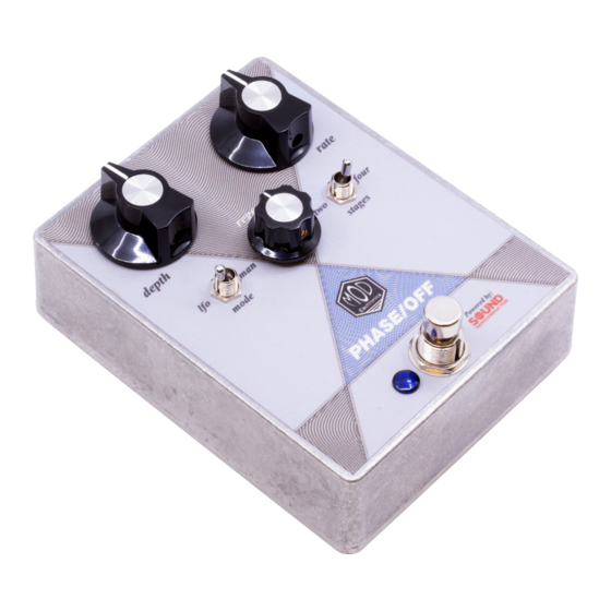
The Phase / Off is a four-stage phaser based around the Sound Semiconductor SSI2140 voltage-controlled
multi-mode filter. This pedal offers classic phasing effects along with plenty of control to dial in the perfect
amount of modulation using the Depth, Rate, and Regen knobs. The Stages switch can change the Phase /
Off from four-stage phaser to a two-stage phaser providing a wide variety of different phasing sounds.
Change the Mode switch from LFO to Manual to use the Phase / Off in fixed phase mode controlled by the
Depth knob for unique filtering effects.
®
The Phase / Off pedal kit is the second entry in the Nexus Series from Mod
Electronics. This series
®
features a PCB base rather than the Mod
Electronics' traditional point-to-point wiring kits to offer builders
an even wider variety of effects to build. The Phase / Off is a great pedal for intermediate skill sets. It
features an all through-hole build with pre-soldered SMT SSI2140.
The pedal operates on 9VDC. A center negative power supply is required for use (not included with kit).
There is no battery connection. The pedal draws ~50mA. The enclosure size is a standard 1590BB (4.7" x
3.7" x 1.34").
Phase / Off
Copyright © 2023 by modelectronics.com
Advertisement
Table of Contents

Related Manuals for Mod Nexus Series


Summary of Contents for Mod Nexus Series
- Page 1 Change the Mode switch from LFO to Manual to use the Phase / Off in fixed phase mode controlled by the Depth knob for unique filtering effects. ® The Phase / Off pedal kit is the second entry in the Nexus Series from Mod Electronics. This series ®...
-
Page 2: Table Of Contents
Table of Contents Page Section Notes on PCB Construction Parts Lists PCB Bill of Materials 8-11 Applying The Sticker Main PCB Construction 13-18 Footswitch PCB Construction Jack PCB Construction Final Assembly 21-23 Phase / Off Controls Schematic 25-27 Required Tools Adjustable Wrench Cutters Lead Formers... -
Page 3: Notes On Pcb Construction
Notes on PCB Construction This section is intended for those unfamiliar or new to constructing circuit boards. Lead Spacing Components are made in two common mounting types, radial and axial. Radial components feature leads that are parallel and oriented in the same direction whereas the leads of axial components protrude from each end of the component oriented in opposite directions. -
Page 4: Parts Lists
Main PCB Parts List R-N100 Qty 2 100Ω 1/4W Metal Film Resistor R-N200 Qty 4 200Ω 1/4W Metal Film Resistor R-N1K Qty 1 1KΩ 1/4W Metal Film Resistor R-N3K Qty 1 3KΩ 1/4W Metal Film Resistor R-N5D1K Qty 1 5.1KΩ 1/4W Metal Film Resistor R-N8D2K Qty 1 8.2KΩ... - Page 5 Main PCB Parts List (cont.) P-Q971 Qty 2 1N4148 Small Signal Diode P-Q1N5817 Qty 1 1N5817 Schottky Diode C-R82-1N Qty 4 1nF Box Film Capacitor DOWN VIEW C-R82-1N5 Qty 1 1.5nF Box Film Capacitor DOWN VIEW C-R82-100N Qty 1 100nF (.1uF) Box Film Capacitor DOWN VIEW C-R82-470N...
- Page 6 Main PCB Parts List (cont.) R-VAM10KA-SS-PCL Qty 1 A10KΩ 16mm PCB Mount Potentiometer DOWN VIEW R-VAM10KL-SS-PCL Qty 1 B10KΩ 16mm PCB Mount Potentiometer DOWN VIEW R-VAM50KL-SS-PCL Qty 1 B50KΩ 16mm PCB Mount Potentiometer DOWN VIEW R-VCOVER-LP16 Qty 1 16mm Potentiometer Cover DOWN VIEW BOTTOM...
- Page 7 Footswitch PCB Parts List R-G1K Qty1 1KΩ 1/8W Metal Film Resistor P-L353 Qty 1 Blue 5mm Diffused LED Schottky Diode DOWN VIEW P-L710-BLU Qty 1 Blue LED Lens Qty 1 Low Profile 3PDT Footswitch P-H501-LP Qty 1 Footswitch PCB K-905-PCB-SWITCH Jack PCB Parts List Qty 1 DC Barrel Jack...
- Page 8 Enclosure Parts List P-K371 Qty 1 Small Knob P-K381 Qty 2 Large Knob P-H1590BBCE Qty 1 Aluminum 1590BB Enclosure K-905-LABEL Qty 1 Phase / Off Sticker Phase / Off...
-
Page 9: Pcb Bill Of Materials
PCB BOMs Main PCB SIDE 1 SIDE 2 ✔ Type Part Value 10KΩ 1/4W Metal Film Resistor 200Ω 1/4W Metal Film Resistor 10KΩ 1/4W Metal Film Resistor 10KΩ 1/4W Metal Film Resistor 200Ω 1/4W Metal Film Resistor 10KΩ 1/4W Metal Film Resistor 33KΩ... - Page 10 PCB BOMs Main PCB (cont.) ✔ Type Part Value 200Ω 1/4W Metal Film Resistor 10KΩ 1/4W Metal Film Resistor 16KΩ 1/4W Metal Film Resistor 1KΩ 1/4W Metal Film Resistor 100KΩ 1/4W Metal Film Resistor 51KΩ 1/4W Metal Film Resistor 10KΩ 1/4W Metal Film Resistor 10KΩ...
- Page 11 PCB BOMs Main PCB (cont.) Type Part Value 100nF Ceramic Capacitor 100nF Ceramic Capacitor 100nF Ceramic Capacitor 100nF Ceramic Capacitor Film Capacitor Film Capacitor 470pF Ceramic Capacitor 1.5nF Film Capacitor 100nF Ceramic Capacitor 100nF Film Capacitor 10pF Ceramic Capacitor 100uF Electrolytic Capacitor 470nF Film Capacitor...
- Page 12 PCB BOMs Switch PCB SIDE 1 SIDE 2 ✔ Type Part Value RLED 1KΩ 1/8W Metal Film Resistor Blue 5mm Diffused LED Footswitch 3PDT Low Profile 3PDT Footswitch Ribbon Cable 6 Conductor 6 Conductor Flexstrip Ribbon Jack PCB SIDE 1 SIDE 2 ✔...
-
Page 13: Applying The Sticker
Applying The Sticker Note: Do not apply the sticker until directed to do so at Step 73 in the instructions. Locate the top of the pedal as well as the top of the sticker. The cover of the instructions for your kit will have an image of the pedal that can be used for reference. -
Page 14: Main Pcb Construction
Main PCB Construction Locate the Main PCB. The following steps will cover the placement and soldering of all parts that are mounted on this PCB. Use the BOM and Parts List as references. Part 1: Resistors 1: Insert a 10KΩ resistor at R1. Its color bands are brown, black, black, red, brown. - Page 15 Main PCB Construction Part 1: Resistors (cont.) 16: Insert a 10KΩ resistor at R16. Its color bands are brown, black, black, red, brown. 17: Insert a 200Ω resistor at R17. Its color bands are red, black, black, black, brown. 18: Insert a 10KΩ resistor at R18. Its color bands are brown, black, black, red, brown.
- Page 16 Main PCB Construction Part 1: Resistors (cont.) 31: Insert a 1MΩ resistor at R31. Its color bands are brown, black, black, yellow, brown. 32: Insert a 3KΩ resistor at R32. Its color bands are orange, black, black, brown, brown. 33: Insert a 100Ω resistor at R33. Its color bands are brown, black, black, red, brown.
- Page 17 Main PCB Construction Part 4: Capacitors 43: Insert a 1nF film capacitor at C1. This is the rectangular capacitor marked 1nJ100. 44: Insert a 1nF film capacitor at C2. This is the rectangular capacitor marked 1nJ100. 45: Insert a 470nF film capacitor at C3. This is the rectangular capacitor marked .47K63.
- Page 18 Main PCB Construction Part 4: Capacitors (cont.) 57: Insert a 1.5nF film capacitor at C15. This is the rectangular capacitor marked 1n5K100. 58: Insert a 100nF ceramic capacitor at C16. This is the circular capacitor marked 104. 59: Insert a 100nF film capacitor at C17. This is the rectangular capacitor marked .1J100.
- Page 19 Main PCB Construction Part 5: Switches and Potentiometers 63: Remove all of the mounting hardware and insert the SPDT mini toggle switch at SW1 on side 2 of the PCB. 64: Remove all of the mounting hardware and insert the DPDT mini toggle switch at SW2 on side 2 of the PCB.
-
Page 20: Footswitch Pcb Construction
Footswitch PCB Construction Locate the Footswitch PCB. The following steps will cover the placement and soldering of all parts that are mounted on this PCB. Use the BOM and Parts List as references. Mount All Components 71: Insert the 1/8W 1KΩ resistor at RLED. Its color bands are brown, black, black, brown, brown. -
Page 21: Jack Pcb Construction
Jack PCB Construction Locate the Jack PCB. The following steps will cover the placement and soldering of all parts that are mounted on this PCB. Use the BOM and Parts List as references. Mount All Components 77: Cut and strip a one inch piece of both the black and white 24AWG wire. On side 2 of the Jack PCB, solder the white wire to the +9V pad and the black wire to the GND pad. -
Page 22: Final Assembly
Final Assembly Locate the three PCBs and the enclosure. The following steps will cover the final assembly of the pedal by connecting and mounting these three boards. Use the BOM and Parts List as references. Part 1: Connect the Footswitch PCB to the Main PCB 83: Insert the 6 conductor ribbon cable through the six holes near the logos on side 1 of the main PCB. - Page 23 Final Assembly Part 3: Attach the Jack PCB to the Enclosure 88: Mount the DC jack to the center hole of the top side of the enclosure. Orient the jack so the large center pin lug is to the left and the ring lug is to the right. Tighten down the mounting nut. 89: Now secure the jack PCB to the enclosure.
- Page 24 Final Assembly Part 5: Insert the ICs 91: Insert the LM311 in the U2 socket. Be sure to orient the IC correctly. The small dot on the top should be closest to the notch in the IC socket. 92: Insert the TL074 in the U3 socket. Be sure to orient the IC correctly.
-
Page 25: Phase / Off Controls
Phase / Off Controls Effect Output Power Input - 9VDC Center Negative Effect Input Depth Control - In LFO Mode this knob sets the amount of modulation. Counterclockwise for zero modulation and clockwise for full modulation. In Manual Mode this knob sets the static phase amount. -
Page 26: Schematic
Copyright © 2023 By Mod® Electronics Phase / Off (K-905) Main PCB Schematic... - Page 27 Copyright © 2023 By Mod® Electronics Phase / Off (K-905) Main PCB Schematic...
- Page 28 Copyright © 2023 By Mod® Electronics Phase / Off (K-905) Main PCB Schematic...
Need help?
Do you have a question about the Nexus Series and is the answer not in the manual?
Questions and answers