Advertisement
Quick Links
SEISMIC
SHIFT
SEISMIC
SHIFT
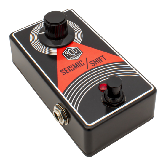
The Seismic Shift is a JFET boost based on one of the earliest effects to ever be
used on stage. This pedal adds subtle color to a guitar's sound while
maintaining the natural tone of the guitar. It packs a serious punch that can cut
through any mix when soloing or whenever some extra "umph" is required. The
Seismic Shift pairs nicely with amps and other pedals. Place it ahead of tubes,
preamps, overdrives, distortions, and fuzz pedals to shift your gear onto a new
level.
The Seismic Shift pedal kit is the introduction to the Nexus Series from Mod
Electronics. This series features a PCB base rather than the Mod Electronics'
traditional point-to-point wiring kits to offer builders an even wider variety of
effects to build. The Seismic Shift kit is designed for all skill sets and is the
perfect first build for those unfamiliar with PCB construction.
The pedal operates on both 9VDC and 18VDC. A center negative power supply
is required for use (not included w/ kit). There is no battery connection. When
using 9VDC the pedal draws 8mA. When using 18VDC the pedal draws 16mA.
The enclosure size is a standard 1590B (4.4" x 2.4" x 1.2").
Seismic Shift JFET Boost
Copyright © 2021 by modelectronics.com
Advertisement

Related Manuals for Mod Nexus Series


Summary of Contents for Mod Nexus Series
- Page 1 The Seismic Shift pedal kit is the introduction to the Nexus Series from Mod Electronics. This series features a PCB base rather than the Mod Electronics’...
-
Page 2: Table Of Contents
Table of Contents Page Section Notes on PCB Construction Parts Lists PCB BOM's Applying The Sticker Main PCB Construction 3PDT PCB Construction and Enclosure Parts 10-13 Calibration Schematic Required Tools Adjustable Wrench Cutters Lead Formers Needlenose Pliers Phillips Head Screwdriver Ruler Small Flat Head Screwdriver Solder... -
Page 3: Notes On Pcb Construction
Notes on PCB Construction This section is intended for those unfamiliar with or new to constructing circuit boards. Lead Spacing Components are made in two common mounting types, radial and axial. Radial components feature leads that are parallel and oriented in the same direction whereas the leads of axial components protrude from each end of the component oriented in opposite directions. -
Page 4: Parts Lists
R-N100K Qty 2 100KΩ 1/4W Metal Film Resistor R-O1M Qty 1 1MΩ 1/4W Metal Film Resistor P-Q1N5817 Qty 1 1N5817 Schottky Diode C-ET50-50-MOD Qty 1 50uF Electrolytic Capacitor C-ET250-25-MOD Qty 1 250uF Electrolytic Capacitor C-D100N-50 Qty 1 100nF Ceramic Capacitor... - Page 5 3PDT PCB Parts List P-L352 Qty 1 Red 5mm Diffused LED R-N1K Qty 1 1KΩ 1/4W Metal Film Resistor P-H501-L-BLK Qty 1 Soft Click 3PDT Footswitch P-PC-3PDT-BOARD Qty 1 3PDT PCB Enclosure Parts Lists P-L710-RED Qty 1 Red LED Lens P-JB-IN-U Qty 1 Low Profile DC Barrel Jack...
-
Page 6: Pcb Bom's
PCB BOM's Seismic Shift PCB Part Value Type 100Ω 1/4W Metal Film Resistor 100KΩ 1/4W Metal Film Resistor 1MΩ 1/4W Metal Film Resistor 22KΩ 1/4W Metal Film Resistor 100KΩ 1/4W Metal Film Resistor 1N5817 Schottky Diode 250uF Electrolytic Capacitor 100nF Ceramic Capacitor 100pF Ceramic Capacitor... -
Page 7: Applying The Sticker
Applying The Sticker Locate the top of the pedal as well as the top of the sticker. The cover of the instructions for your kit will have an image of the pedal that can be used for reference. Peel the backing from the sticker. Carefully line up the top edge of the sticker with the top of the pedal. -
Page 8: Main Pcb Construction
Main PCB Construction Locate the Seismic Shift Main PCB. The following steps will cover the placement and soldering of all parts that are mounted on this PCB. Use the BOM and Parts List as references. Part 1: Resistors Locate the 100Ω resistor. Its color bands are brown, black, black, black, brown. - Page 9 Main PCB Construction Part 2: Solid State Components Locate the 1N5817 diode. When inserting the diode, note the orientation of the band. This should match the orientation on the silkscreen. Use the .4 notch on the lead formers. Insert and solder this diode at D1. Locate the PF5102 JFET.
- Page 10 Main PCB Construction Part 4: Radial Capacitors (cont.) Locate the 100pF ceramic capacitor. This is the circular capacitor marked 101. Insert and solder this capacitor at C3. Locate the 47nF film capacitor. This is the rectangular capacitor marked 473. Insert and solder this capacitor at C4. Locate the 100nF film capacitor.
-
Page 11: 3Pdt Pcb Construction And Enclosure Parts
3PDT PCB Construction and Enclosure Parts Locate the 3PDT PCB. The following steps will cover the placement and soldering of all parts that are mounted on this PCB. Use the BOM and Parts List as references. Part 1: Board-Mounted Components Locate the 1KΩ... - Page 12 3PDT PCB Construction and Enclosure Parts (cont.) Locate the two 1/4" jacks. Solder the four 1 3/4" wires to the sleeve and tip of each jack. Part 3: Mounting to the Enclosure Locate the red LED, the lens, and 1590B enclosure. Insert the LED lens into the small hole directly above the large footswitch hole.
- Page 13 3PDT PCB Construction and Enclosure Parts (cont.) Locate the DC jack and mount it in the hole on the top side of the enclosure. Run the two 6" wires connected to the POWER GND and POWER V+ along the bottom left edge inside the enclosure then connect the V+ wire to the longer lug and the GND wire to the shorter lug.
- Page 14 3PDT PCB Construction and Enclosure Parts (cont.) Part 4: Mounting The Main PCB Remove the nut and washer from the 9mm pot mounted to the main PCB. Grip the small metal tab with a pair of pliers and gently rock the tab until it snaps off.
-
Page 15: Calibration
Calibration Calibrating By Ear Locate the 5KΩ trimmer on the main PCB. With a small flat head screwdriver rotate the trimmer fully clockwise. This is a 25 turn trimmer. A quiet clicking sound will occur once the end has been reached. -
Page 16: Schematic
1N5817 250uF 100nF 100nF 500K PF5102 100K 47nF 100pF 50uF 100K COPYRIGHT © 2021 BY MODELECTRONICS.COM Seismic Shift (K-902) Main PCB Schematic...
Need help?
Do you have a question about the Nexus Series and is the answer not in the manual?
Questions and answers