
Related Manuals for Schmalz RECBi


Summary of Contents for Schmalz RECBi
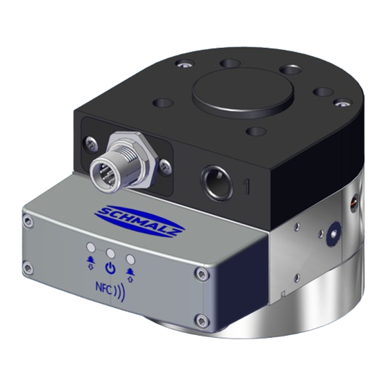
- Page 1 Operating instructions Ejector Module RECBi WWW.SCHMALZ.COM EN-US · 30.30.01.03601 · 00 · 01/23...
- Page 2 Published by © J. Schmalz GmbH, 01/23 This document is protected by copyright. J. Schmalz GmbH retains the rights established thereby. Repro- duction of the contents, in full or in part, is only permitted within the limits of the legal provisions of copyright law. Any modifications to or abridgments of the document are prohibited without explicit writ- ten agreement from J. Schmalz GmbH.
-
Page 3: Table Of Contents
Contents Contents 1 Important Information ........................... 5 Note on Using this Document...................... 5 The technical documentation is part of the product ................ 5 Type Plate............................. 5 Symbols.............................. 6 2 Fundamental Safety Instructions........................ 7 Intended Use ............................ 7 Non-Intended Use.......................... 7 Personnel Qualification ........................ - Page 4 Contents 5.21 IO-Link Events ............................ 30 6 Technical Data............................... 31 General Parameters ........................... 31 Performance Data.......................... 31 Electrical Specifications ........................ 31 Maximum Forces .......................... 32 Dimensions ............................ 32 Factory Settings.......................... 34 Pneumatic Circuit Plans ........................ 35 7 Transportation and Storage......................... 36 Checking the Delivery........................
-
Page 5: Important Information
ð Failure to follow the instructions in these Operating instructions may result in injuries! ð Schmalz is not liable for damage or malfunctions that result from failure to heed these instructions. If you still have questions after reading the technical documentation, contact Schmalz Service at: www.schmalz.com/services... -
Page 6: Symbols
1 Important Information 1.4 Symbols This symbol indicates useful and important information. ü This symbol represents a prerequisite that must be met prior to an operational step. 4 This symbol represents an action to be performed. ð This symbol represents the result of an action. Actions that consist of more than one step are numbered: 1. -
Page 7: Fundamental Safety Instructions
2.2 Non-Intended Use Schmalz does not accept any liability for any direct or indirect losses or damages that result from using the product. This applies, in particular, to any use of the product that is not in accordance with the in- tended purpose and to any use that is not described or mentioned in this documentation. -
Page 8: Warnings In This Document
2 Fundamental Safety Instructions 2.4 Warnings in This Document Warnings warn against hazards that may occur when handling the product. The signal word indicates the level of danger. Signal word Meaning Indicates a medium-risk hazard that could result in death or serious injury if WARNING not avoided. -
Page 9: Modifications To The Product
4 Do not walk, stand or work under suspended loads. 2.6 Modifications to the Product Schmalz assumes no liability for consequences of modifications over which it has no control: 1. The product must be operated only in its original condition as delivered. -
Page 10: Criteria For Use In Collaborative Applications
2 Fundamental Safety Instructions 2.7 Criteria for Use in Collaborative Applications 1) Automation cell 2) Coexistence The following criteria justify the suit- ability of the gripper for use in collabo- rative applications: See the adjacent image, Figure 3) and The gripper has an inherently safe de- sign and rounded edges and shapes that prevent hazards. -
Page 11: Product Description
3 Product description 3 Product description 3.1 Product Description The products differ with regard to the basic position of the ejector module in the de-energized state NO (normally open) and NC (normally closed). The product is designed with an integrated ejector module and is marked “1C” in the type key. Depending on the variant, the product has a different design for the interface to the vacuum gripper. -
Page 12: Product Design
3 Product description 3.2 Part Table Schmalz part no. Version 10.02.03.00434 Digital I/O + IO-Link RECBi 24V-DC NC UNI 1C 10.02.03.00437 Digital I/O + IO-Link RECBi 24V-DC NO UNI 1C 10.02.03.00443 Digital I/O + IO-Link RECBi 24V-DC NC PXR-I 1C 10.02.03.00444... -
Page 13: Led Display
The table below describes the possible states on the LED displays. LED display LED color Behavior SCHMALZ IO-Link product status — None RECBi does not blow off Orange Continuous RECBi blows off “Blow-off” light — None No power supply... -
Page 14: Nfc Interface
In addition to pure read access, the app allows you to ac- tively write the parameters of the device via NFC. The “Schmalz ControlRoom” app is available in the Google Play Store or Ap- ple App Store. -
Page 15: Io-Link Operating Mode
• Energy and process control (EPC) functions This allows all modifiable parameters to be read, modified and written back to the RECBi directly via the higher-level controller. Evaluation of the condition monitoring and energy monitoring results allows you to draw direct conclu- sions regarding the current handling cycle and perform trend analyses. -
Page 16: Process Data
4 IO-Link Operating Mode 4.2 Process Data The cyclical process data is used to control the product and receive current information reported from the component. There is a distinction between the: • Input data (Process Data In) and • Output data for the control (Process data out) The input data Process data in is used to report the following information cyclically: •... -
Page 17: Description Of Functions
5 Description of Functions 5 Description of Functions 5.1 Monitoring the System Vacuum and Defining Switching Points The product has integrated sensors for measuring the vacuum. The current vacuum value and current pressure values can be retrieved via IO-Link. Two independent switching points (SP1 and SP2) can be set. Each switching point has an activation point and a corresponding hysteresis (RP1 and RP2). -
Page 18: Production Setup Profiles
5 Description of Functions Overview of switching points P0; the specified parameters apply to production setup profile P0. For other profiles, the data can be taken from the data dictionary. ISDU [hex] Limit value parame- Description Factory P0: 0x0064 Vacuum control value 750 mbar Vacuum switching point P0: 0x0065... -
Page 19: Applying Suction To The Workpiece/Part (Vacuum Generation)
5 Description of Functions The following control function operating modes can be chosen: ISDU Parameter Value Description (hex) 0x0044 Ejector module 0x00 No control control mode 0x01 Control function activated 0x02 Control activated, with supervision (onS) Description Description of control functions No control (continuous suc- The ejector produces continuous suction with maximum power. -
Page 20: Depositing The Workpiece/Part (Blowing Off)
Info: In IO-Link mode, the set input process data bit “SP3 Ejector” (part detached) provides you with infor- mation about whether a picked-up part has been deposited (see also “Monitoring System Vacuum and Defining Switching Points”). The RECBi provides three blow-off modes that can be selected using the “Blow-off mode” parameter 0x0045: •... -
Page 21: Automatic Operation
5 Description of Functions 5.5.1 Externally Controlled Blow-Off The ejector switches to blow-off mode for as long as the signal for “Blow-off” mode is present. 5.5.2 Internally Time-Controlled Blow-Off After the suction signal is switched off, the ejector switches to blow-off mode automatically for the set time. -
Page 22: Access Control
5 Description of Functions The device must be restarted by interrupting the supply voltage. 5.8.2 Reset to Factory Settings The system command “Back to box” 0x83 is used to reset all the setting parameters to their factory set- tings. Any IO-Link communication is stopped in doing so. The device must be restarted by interrupting the supply voltage. -
Page 23: Device Data
5.12 Output and Input Signals RECBi variants with an ejector module have signal outputs and inputs and are designed with SIO as well as IO-Link. In SIO mode, all input and output signals are connected to the higher-level control unit (e.g. a robot) di- rectly or via IO fieldbus boxes. -
Page 24: Switch-Off Delay
5 Description of Functions For this purpose, in addition to the power supply lines, one input signal and two output signals must be connected. The product communicates with the control unit via these signals. The signal type for the digital inputs and outputs can switch between PNP and NPN with the parameters “Signal type: SIO outputs of the device”... -
Page 25: Changing The Blow-Off Flow Rate On The Ejector
5 Description of Functions 5.16 Changing the Blow-Off Flow Rate on the Ejector Do not overwind past the stop on the valve screw. The blow off flow rate can be adjusted within the range between 0% and 100%. A valve screw (see the figure below) is located on the side of the ejector module. This valve screw can be used to manually adjust the blow-off flow rate. -
Page 26: Active Profile
5 Description of Functions Device status parameter 0x0024 The device status provides basic status information for the device in the form of a status traffic light: Parameter 0x0024 Status Description Green (0) Device is operating without any errors (Device is operating properly) Yellow (1) Maintenance or adaptation of settings required (Maintenance re- Device status... -
Page 27: Energy And Process Control (Epc)
5 Description of Functions 5.20 Energy and Process Control (EPC) In IO-Link mode, the energy and process control (EPC) function is available. It is subdivided into three modules: • Condition monitoring (CM): Condition monitoring to increase system avail- ability • Energy monitoring (EM): Energy monitoring to optimize the vacuum sys- tem’s energy consumption •... - Page 28 5 Description of Functions Measure the evacuation time t1 (parameter “Evacuation time t1 of last suction cycle” 0x0095): The evacuation time t1 is defined as the time (in ms) from when switching point SP2 is reached until switching point SP1 is reached. If the measured evacuation time t1 (from SP2 to SP1) exceeds the specified value, the “Evacuation time above limit”...
- Page 29 5 Description of Functions 5.20.4 Energy Monitoring (EM) To optimize the energy efficiency of vacuum gripping systems, the device provides a function for measur- ing and displaying the energy and air consumption. The product is not a calibrated measuring device. However, the values may be used as a ref- erence and for comparison measurements.
-
Page 30: Io-Link Events
“Min reached input pressure of last cycle” 0x00A5. 5.21 IO-Link Events The RECBi indicates when specific “events” occur. As a result, these events do not have to be queried us- ing a parameter. These are error messages and warnings. For more information, see the Data Dictionary. -
Page 31: Technical Data
Polarity reversal protec- tion Current consumption — Typical current consump- Max. current consump- (at 24 V) tion tion RECBi 1C – NC 45 mA 45 mA RECBi 1C – NO 65 mA 65 mA NFC Forum Tag type 4 f = 13.56 MHz IO-Link IO-Link 1.1 Baud rate COM2 (38.4 Kbits/s) EN-US ·... -
Page 32: Maximum Forces
6 Technical Data The power supply must correspond to the regulations in accordance with EN60204 (protected extra-low voltage). 6.4 Maximum Forces The holding force of the different grippers is limited; that is, the absorption of load forces and torques is limited. To prevent the load from shifting or even coming loose during the handling process, the operator of the respective gripper is therefore obliged to determine the optimum settings for the permitted process parameters for the handling process (load, acceleration, vacuum level, and so on) by performing testing and carefully increasing the load. - Page 33 6 Technical Data Version UNI 31.5 107. 75.5 1/8" ter- ter- thre thre Version PXRx 31.5 1/8" inter- M12 ex- nal thread ternal thread EN-US · 30.30.01.03601 · 00 · 01/23 33 / 64...
-
Page 34: Factory Settings
6 Technical Data 75.5 All length dimensions given in millimeters [mm]. 6.6 Factory Settings Parameter Value of the factory setting Limit value SP1 750 mbar Reset value RP1 600 mbar Limit value SP2 550 mbar Reset value RP2 540 mbar Blow off time 0.2 s Air saving Activated Continuous suction Deactivated... -
Page 35: Pneumatic Circuit Plans
6 Technical Data 6.7 Pneumatic Circuit Plans Key: Normally closed Normally open Compressed air connection Vacuum connection Exhaust air output EN-US · 30.30.01.03601 · 00 · 01/23 35 / 64... -
Page 36: Transportation And Storage
1. Compare the entire delivery with the supplied delivery notes to make sure nothing is missing. 2. Damage caused by defective packaging or occurring in transit must be reported immediately to the carrier and J. Schmalz GmbH. 7.2 Unpacking the Device Remove product packaging only to the extent required for further internal transport. -
Page 37: Installation
4 Avoid the danger zone. The RECBi may be installed in any position. The RECBi is adapted directly to a handling system or robot. A positioning pin on the housing is used to align the display and suction cup. The illustrations shown below may deviate from the customer’s version because they serve as examples of different versions of the product. -
Page 38: Connecting Compressed Air
8 Installation 8.2 Connecting Compressed Air ü The hose attachment adapter (provided by the customer) is fitted. 4 Connect the compressed air hose for supplying the integrated vacuum generation via the compressed air connection (1) (marked with 1). Use a maximum tightening torque of 2.5 Nm. -
Page 39: Electrical Connection
8 Installation 8.3 Electrical Connection CAUTION Changing output signals when the product is switched on or plug is connected Personal injury or damage to property! 4 The electrical connection must be performed only by specialists who can evaluate the effects of signal changes on the overall system. WARNING Electric shock Risk of injury... - Page 40 8 Installation The table below shows the pin assignment of the electrical connection options in the operating modes SIO and IO-Link: 8-pin M12 con- Symbol Function with SIO Function with IO-Link nector (A-coded) Supply voltage for actuator Supply voltage for sensor Actuator ground “Suction”...
- Page 41 8 Installation Mounting thread 1. Use the universal flange pattern and 4x M6 fe- male thread (1) to install a customer-specific gripping system with a max. tightening torque of 4 Nm. 2. Connect the vacuum gripping system to the vacuum supply. Remove the selected screw for the vacuum supply and install a suitable hose connection.
- Page 42 8 Installation Examples: PXRi PXRx The vacuum supply for the individual suction cups is established via the vacuum connections of the ejector module using hoses. Installing vacuum suction cups ü The required accessories are available. 1. Position the washer (1) and the hollow bolt (2) on the RECB holder.
- Page 43 (5). Screw the vacuum suction cup (5) onto the hollow screw (2) and fasten with a tightening torque of 2.5 Nm. 5. Position the suction cup assembly in the RECBi holder and secure with a tightening torque of 9 Nm using the nut (3).
- Page 44 8 Installation 6. Remove the required number of plugs (6) from the ejector module. 7. Screw the plug-in screw unions (7) into the free vacuum connections and fasten them with a tightening torque of 2.5 Nm. 8. Cut the vacuum hose (8) to length and insert it into the hose connections.
- Page 45 8 Installation ð Example of a fitted RECBi PXR-i with vacuum gripping system EN-US · 30.30.01.03601 · 00 · 01/23 45 / 64...
-
Page 46: Operation
9 Operation 9 Operation 9.1 Safety Instructions for Operation WARNING Change of output signals when product is switched on or plug is connected Risk of injury to persons and damage to property due to uncontrolled movements of the higher-level machine/system! 4 The electrical connection must be performed only by specialists who can evaluate the effects of signal changes on the overall system. -
Page 47: Setting Process Parameters
(load, acceleration, vacuum level, and so on) by performing testing and carefully increasing the load. Schmalz assumes no liability for damages resulting from slippage or the release of the load due to the in- correct adjustment of process parameters. -
Page 48: Help With Malfunctions
I/O sig- 4 Adjust the input and output logic Input and output logic (PNP/NPN) nals from the controller of the RECBi does not match the (PNP/NPN) to the device's electrics input and output logic of the con- trol (PNP/NPN); unsuitable applica-... -
Page 49: Maintenance And Cleaning
Unauthorized disassembly and assembly of the product can lead to complications, as special assembly de- vices are sometimes required. Schmalz stipulates the following checks and check intervals. The operator must comply with the legal regulations and safety regulations applicable at the location of use. These intervals apply to single-shift operation. -
Page 50: Cleaning
11 Maintenance and Cleaning Maintenance task When start- Weekly As required Every six ing work months Visually inspecting the product and its surroundings Check electrical contacts/electrical con- nections/connection cables for damage and function Check the locking device Clean the product Maintain the locking device for and po- sitioning of the loose member The operating instructions are avail-... - Page 51 11 Maintenance and Cleaning If the suction capacity decreases, replace the silencer: The illustrations shown below may deviate from the customer’s version because they serve as examples of different versions of the product. ü Deactivate the device and depressurize the pneumatic systems. ü...
-
Page 52: Replacing The Nozzle
11 Maintenance and Cleaning 5. Push the silencer housing (2) into the ejector module and secure with two screws (tighten- ing torque 0.7 Nm). 11.5 Replacing the Nozzle ü Deactivate the device and depressurize the pneumatic systems. ü The new nozzle is ready for mounting. See accessories. 1. - Page 53 11 Maintenance and Cleaning ð Remove the nozzle from the ejector mod- ule. 4. Check that all O-rings and flaps are present, correctly mounted and lightly greased. Push the new nozzle into the ejector module in the correct position. 5. Push the silencer housing (2) into the ejector module and secure with two screws (tighten- ing torque 0.7 Nm).
- Page 54 11 Maintenance and Cleaning 6. Ensure that the O-ring is fitted on the screw (1) and is lightly greased. Mount the screw (1) and tighten with a torque of 1.5 Nm. 54 / 64 EN-US · 30.30.01.03601 · 00 · 01/23...
-
Page 55: Spare And Wearing Parts
The following list contains the most important spare and wearing parts. Part no. Designation Part type 10.02.03.00422 Silencer spare parts set Spare part ERS RECBi SD 10.02.01.01449 Spare parts set, size: 13 contains: 6x non-return Spare part valve ERS SEP-13 6xRUE-KLAP 10.02.01.01493... -
Page 56: Accessories
13 Accessories 13 Accessories Part no. Designation Note 10.02.03.00441 SD 66.7x24.4x24.5 Silencer RECBi 10.02.03.00453 ZUB RECBi-UNI for universal flange SCHRAUBEN 10.02.03.00454 ZUB RECBi-PXR-I for PXR-I or PXR-X SCHRAUBEN 10.02.03.00412 ZUB RECBi-UNI for universal flange 10.02.03.00413 ZUB RECBi-PXR-I for PXR-I 10.02.03.00414 ZUB RECBi-PXR-X for PXR-X 10.08.09.00032... -
Page 57: Taking The Product Out Of Operation And Disposal
14 Taking the Product Out of Operation and Disposal 14 Taking the Product Out of Operation and Disposal If the product reaches the end of the utilization phase, it may be fully disassembled and disposed of. Only qualified specialist staff may prepare the product for disposal. 1. -
Page 58: Declarations Of Conformity
15 Declarations of Conformity 15.1 EC Conformity EU Declaration of Conformity The manufacturer Schmalz confirms that the product with the name “pneumatic end-of-arm vacuum gen- erator RECBi” that is described in these operating instructions complies with the following applicable EC directives: 2011/65/EU RoHS Directive... - Page 59 15 Declarations of Conformity EN 61000-6-2+AC Electromagnetic compatibility (EMC) - Part 6-2: Generic standards - Immunity for industrial environments EN 61000-6-3+A1+AC Electromagnetic compatibility (EMC) - Part 6-3: Generic standards - Emission standard for residential, commercial and light-industrial environments EN 300 330 Radio equipment in the frequency range 9 kHz to 25 MHz and inductive loop systems in the frequency range 9 kHz to 30 MHz EN IEC 63000...
- Page 60 IO-Link Data Dictionary RECB 1-C 21.10.01.00191/00 06.09.2022 J. Schmalz GmbH Johannes-Schmalz-Str. 1, D 72293 Glatten Tel.: +49(0)7443/2403-0 Fax: +49(0)7443/2403-259 IO-Link Implementation Vendor ID 234 (0xEA) Device ID 100282 (0x0187BA) SIO-Mode IO-Link Revision 1.1 (compatible with 1.0) IO-Link Bitrate 38.4 kBit/sec (COM2)
- Page 61 Size Access Default Value Remark Range Identification Device Management 0x0010 Vendor name 0…32 bytes J. Schmalz GmbH Manufacturer designation 0x0011 Vendor text 0…32 bytes Innovative Vacuum Solutions Internet address 0x0012 Product name 0…32 bytes RECB_1C Product name 0x0013 Product ID 0…32 bytes...
- Page 62 Production Setup - Profile P2 0 = not active (off) 0x00C8 Air-Saving function byte 1 = active (on) 2 = active with supervision (onS) 0 = off, 0x00C9 Disable continous sucking byte 1 = on 999 > SP1 0x00CA Switchpoint 1 (SP1) bytes Unit: 1mbar...
- Page 63 Timing Unit: 1ms Evacuation time t0 of last suction-cycle 0x0094 bytes Time from suction start to reaching SP2 Unit: 1ms 0x0095 Evacuation time t1 of last suction-cycle bytes Time from reaching SP2 to reaching SP1 0x00A6 Total cycle time of last cycle bytes Unit: 1ms ...
- Page 64 At Your Service Worldwide Vacuum automation Handling systems WWW.SCHMALZ.COM/AUTOMATION WWW.SCHMALZ.COM/EN-US/VACUUM-LIFTERS- AND-CRANE-SYSTEMS J. Schmalz GmbH Johannes-Schmalz-Str. 1 72293 Glatten, Germany T: +49 (0) 7443 2403-0 schmalz@schmalz.de WWW.SCHMALZ.COM...
Need help?
Do you have a question about the RECBi and is the answer not in the manual?
Questions and answers