
Related Manuals for Schmalz SCPSi


Summary of Contents for Schmalz SCPSi
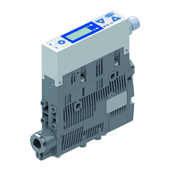
- Page 1 Operating Instructions Compact Ejector SCPSi, SCPSi-2 WWW.SCHMALZ.COM EN-US · 30.30.00.00424 · 07 · 10/23...
- Page 2 Published by © J. Schmalz GmbH, 10/23 This document is protected by copyright. J. Schmalz GmbH retains the rights established thereby. Repro- duction of the contents, in full or in part, is only permitted within the limits of the legal provisions of copyright law. Any modifications to or abridgments of the document are prohibited without explicit writ- ten agreement from J. Schmalz GmbH.
-
Page 3: Table Of Contents
Contents Contents Contents .............................. 000 1 Important Information ........................... 6 Note on Using this Document...................... 6 The technical documentation is part of the product ................ 6 Type Plate............................. 6 Symbols.............................. 7 2 Fundamental Safety Instructions........................ 8 Intended Use ............................ 8 Non-Intended Use.......................... - Page 4 Contents Changing the Blow-Off Flow Rate on the Ejector ................ 34 Monitoring the Supply Voltages....................... 35 Evaluating the Inlet Pressure ...................... 35 7.10 Calibrating the Vacuum Sensor ...................... 35 7.11 Signal Output............................. 36 7.12 Control of the Ejector Variants ...................... 36 7.13 Vacuum unit............................
- Page 5 Contents 14 Warranty ............................... 67 15 Spare and Wearing Parts.......................... 68 16 Accessories .............................. 69 17 Decommissioning and Disposal ........................ 70 17.1 Disposing of the Product........................ 70 17.2 Materials Used ........................... 70 18 Declarations of Conformity.......................... 71 18.1 EC Conformity ............................ 71 18.2 UKCA Conformity ..........................
-
Page 6: Important Information
ð Failure to follow the instructions in these Operating instructions may result in injuries! ð Schmalz is not liable for damage or malfunctions that result from failure to heed these instructions. If you still have questions after reading the technical documentation, contact Schmalz Service at: www.schmalz.com/services... -
Page 7: Symbols
1 Important Information 1.4 Symbols This symbol indicates useful and important information. ü This symbol represents a prerequisite that must be met before an action is performed. 4 This symbol represents an action to be performed. ð This symbol represents the result of an action. Actions that consist of more than one step are numbered: 1. -
Page 8: Fundamental Safety Instructions
Intended use includes observing the technical data and the installation and operating instructions in this manual. 2.2 Non-Intended Use Schmalz accepts no liability for damages caused by non-intended usage of the ejector. In particular, the following are considered non-intended use: •... -
Page 9: Warnings In This Document
2 Fundamental Safety Instructions 2.4 Warnings in This Document Warnings warn against hazards that may occur when handling the product. The signal word indicates the level of danger. Signal word Meaning Indicates a medium-risk hazard that could result in death or serious injury if WARNING not avoided. -
Page 10: Modifications To The Product
4 Do not look into vacuum openings such as suction lines and hoses. 2.6 Modifications to the Product Schmalz assumes no liability for consequences of modifications over which it has no control: 1. The product must be operated only in its original condition as delivered. -
Page 11: Product Description
3 Product Description 3 Product Description 3.1 Ejector Designation The breakdown of the item designation (e.g. SCPSi 10 M G2 NO M12-5) is as follows: Property Variants Type of ejector SCPSi Performance class 07, 10, 15, 2-07, 2-09, 2-14 Power blow off function Pneumatic connection G02 (1/8"... -
Page 12: Display And Operating Element In Detail
3 Product Description 3.3 Display and Operating Element in Detail The ejector is fitted with 3 buttons, the 3-digit display and 4 LEDs for status information to ensure simple operation. MENU BUTTON UP BUTTON Display LED vacuum limit value H2 LED vacuum limit value H1 LED process state “suction”... - Page 13 3 Product Description Meaning of the Vacuum Limit Value LEDs The LEDs for the vacuum limit values H1 and H2 indicate the current level of the system vacuum relative to the configured limit values. Their display is independent of the switching function and assignment of the output, and independent of whether the condition monitoring function is active.
-
Page 14: Technical Data
4 Technical Data 4 Technical Data 4.1 Display Parameters Parameter Value Unit Comment Display digit Red 7-segment LED display Solution ±1 mbar — Accuracy ±3 % FS = 25° C, based on FS (full-scale) final value Linearity error ±1 — Offset error ±2 mbar After zero-point adjustment, without vacuum Temperature influ-... -
Page 15: Factory Settings
4 Technical Data Parameter Symbol Limit values Unit Comment Voltage of signal input (PNP) — In reference to Gnd A/SA Voltage of signal input (NPN) — In reference to U A/SA Current of signal input (PNP) — — — Current of signal input (NPN) —... -
Page 16: Performance Data
4 Technical Data 4.5 Performance Data Type SCPSi-07 SCPSi-10 SCPSi-15 Nozzle size [mm] Max. vacuum [mbar] Suction rate [l/min] Max. blow off capacity [l/min] Air consumption (suction) (l/min] Sound level , unobstructed suction [dB(A)] Sound level , suction [dB(A)] Weight [kg] 0.195... -
Page 17: Dimensions
4 Technical Data 4.6 Dimensions Version without power blow-off (d1) (d2) 18.6 6 / 8 6 / 8 1/8" 1/8" M12x 40.8 47.5 inter- inter- 1 ex- ternal threa threa threa 16.5 83.8 91.5 29.5 83.8 36.9 EN-US · 30.30.00.00424 · 07 · 10/23 17 / 86... -
Page 18: Pneumatic Circuit Plans
4 Technical Data Version with power blow-off (M) (d1) (d2) 18.6 6 / 8 6 / 8 1/8" 1/8" M12x 117.8 59.6 66.35 inter- inter- 1 ex- ternal threa threa threa 16.5 21.8 83.8 91.5 29.5 54.8 36.9 Depending on the design of the push-in connection. All specifications are in mm 4.7 Pneumatic Circuit Plans The pneumatic circuit diagrams are shown in simplified form. - Page 19 4 Technical Data Pneumatic circuit diagrams for single-stage version ...NO..NC... SCPSi...IMP SCPSi...IMP...M EN-US · 30.30.00.00424 · 07 · 10/23 19 / 86...
- Page 20 4 Technical Data ...NO... M ...NC...M Pneumatic circuit diagrams for two-stage version ... NO..NC... 20 / 86 EN-US · 30.30.00.00424 · 07 · 10/23...
- Page 21 4 Technical Data ...IMP..IMP...M ...NO...M ...NC...M EN-US · 30.30.00.00424 · 07 · 10/23 21 / 86...
-
Page 22: Operating And Menu Concept
5 Operating and Menu Concept 5 Operating and Menu Concept The unit is operated via three buttons on the foil keypad. The parameters are set via software menus. The current system status and the settings are shown on a display. Navigation is divided into three menus: •... -
Page 23: Configuration Menu
5 Operating and Menu Concept 5.2.2 Changing the Parameters of the Main Menu 1. Open the main menu by pressing the MENU button. 2. Use the UP or DOWN button to select the desired adjustable parameter. 3. Confirm the selection with the MENU button. 4. -
Page 24: System Menu
5 Operating and Menu Concept Display Parameter Possible settings Explanation code Vacuum unit Define the displayed vacuum unit Vacuum level in mbar Vacuum level in inHg Vacuum level in kPa Display rotation Display configuration Standard Rotated 180° Display in Eco Configure the display mode Eco mode is deactivated –... -
Page 25: Individual Functions
5 Operating and Menu Concept 5.4.2 Displaying Data in the System Menu 1. Open the system menu by simultaneously pressing the MENU and UP buttons for more than 3 sec- onds. ð During activation, -5- appears. 2. Use the UP or DOWN button to select the value to be displayed. 3. -
Page 26: Operating Modes
6 Operating Modes 6 Operating Modes All the ejectors in this series can be operated in two operating modes: • Via direct connection to inputs and outputs (standard I/O = SIO) or • Connection via a communication line (IO-Link) By default, the ejector always runs in SIO mode, but it can be switched in and out of IO-Link mode by an IO-Link master at any time. - Page 27 6 Operating Modes The process data is exchanged cyclically between the IO-Link master and the product (data transmission rate with COM2 = 38.4 kBit/sec.). ISDU parameter data (acyclical data) is exchanged only on request. It is exchanged by the user program in the control unit (e.g.
- Page 28 6 Operating Modes 6.2.3 IO-Link The ejector can be operated in IO-Link mode to enable intelligent communication with a controller. The ejector’s parameters can be set remotely using IO-Link mode. The energy and process control (EPC) func- tion is also available in IO-Link mode. It is divided into 3 modules: •...
-
Page 29: General Description Of Functions
7 General Description of Functions 7 General Description of Functions 7.1 Applying Suction to the Workpiece/Part (Vacuum Generation) WARNING The Compressed Air Supply of the Vacuum Generator Fails During Operation. Danger of falling parts because the vacuum for the vacuum gripper collapses quickly. 4 Ensure that the compressed air supply does not fail during operation. -
Page 30: Depositing The Workpiece/Part (Blowing Off)
7 General Description of Functions The diagram below shows the vacuum curve for when the air saving function is activated: Vacuum [mbar] H1-h1 OUT=on H2-h2 OUT=off Vacuum on Time [s] The ejector has an integrated air saving function and automatically regulates the vacuum in suction mode: •... -
Page 31: Operating Modes
7 General Description of Functions 7.3 Operating Modes The ejector can be operated in four operating modes: • Direct connection to inputs and outputs (standard I/O = SIO) • Connection via the communication line (IO-Link) • “Manual mode,” operation using the ejector buttons •... -
Page 32: Vacuum Monitoring
7 General Description of Functions Manual suction 1. Press the UP button to activate “suction” on the ejector. 2. The DOWN or UP button exits “suction” mode again. When the air saving function is switched on, it is also active in the “Manual Operation” operating mode. Manual blow off 4 Press the DOWN button to activate “blow off”... - Page 33 7 General Description of Functions Operating mode Explanation No control/continuous suction, H1 The ejector produces continuous suction with maximum in hysteresis mode power. This setting is recommended for very porous workpieces, which would otherwise cause vacuum gener- [ctr] => [oFF] ation to switch on and off continuously due to the high rate of leakage.
-
Page 34: Blow Off Functions
7 General Description of Functions 7.6 Blow off Functions The ejector has three blow off functions in three different modes. The function is set under the [blo] menu item in the configuration menu or via IO-Link. Explanations of the blow off modes: Description Explanation Externally controlled blow... -
Page 35: Monitoring The Supply Voltages
7 General Description of Functions 7.8 Monitoring the Supply Voltages The ejector is not a voltage meter! However, the measured values and the system responses derived from them provide a helpful diagnostics tool for condition monitoring. The ejector measures the supply voltages U . -
Page 36: Signal Output
7 General Description of Functions 7.11 Signal Output 7.11.1 Setting the Output Function The ejector has a signal output. The signal output can be configured using the corresponding menu item. The signal output OUT can be switched between [no] (normally open) and [nc] (normally closed) con- tact. -
Page 37: Vacuum Unit
7 General Description of Functions 7.12.2 Control Concept for NC Ejectors “Suction” [IN1] “Blow off” [IN2] “Suction” state 0 bar “Blow off” state 0 bar 7.12.3 Control Concept for IMP Ejector Variant “Suction” [IN1] “Blow off” [IN2] “Suction” state “Blow off” state On delivery, the ejector variant IMP is set to “pneumatically OFF.” The ejector only produces suction after a valid pulse has been applied at the “suction”... -
Page 38: Switch-Off Delay
7 General Description of Functions The selection of the vacuum unit only affects the display. The units of the parameters that can be accessed via IO-Link are not affected by this setting. 7.14 Switch-off Delay You can use this function to set a switch-off delay for the H2 “Part Present” check signal. This can be used to mask short-term fluctuations in the vacuum level of the vacuum system. -
Page 39: Resetting To Factory Settings
7 General Description of Functions 7.16.2 Device Access Locks In IO-Link mode, the “Device access locks” default parameter is available to prevent changes to parameter values using the user menu or IO-Link. You can also prevent the use of the Data storage mechanism de- scribed in IO-Link Standard V1.1. -
Page 40: Counters
7 General Description of Functions 7.18 Counters The ejector has two internal counters, [cc1] and [cc2], which cannot be erased: Counter 1 increases with each valid pulse at the “suction” signal input, meaning that it counts all the suc- tion cycles during the ejector’s service life. Counter 2 increases each time the “suction” valve is switched on. -
Page 41: Displaying The Serial Number
7 General Description of Functions Displayed section 02. 0 2. 0 0 Digit block The part number in this example is 10.02.02.00383. 4 To exit the function, press the MENU button. 7.21 Displaying the serial number The serial number indicates the production period of the ejector. ü... -
Page 42: Energy And Process Control (Epc)
7 General Description of Functions 7.24 Energy and Process Control (EPC) In IO-Link mode, the energy and process control (EPC) function is available. It is subdivided into three modules: • Condition monitoring (CM): Condition monitoring to increase system avail- ability • Energy monitoring (EM): Energy monitoring to optimize the vacuum sys- tem’s energy consumption •... - Page 43 7 General Description of Functions Monitoring the Control: If the vacuum limit value H1 is never reached during the suction cycle, the “H1 not reached” condition monitoring warning is triggered and the system status light switches to yellow. This warning is available at the end of the current suction phase and remains active until the next suction cycle.
- Page 44 7 General Description of Functions Vacuum Vacuum H1-h1 H-h1 Time Time Dynamic pressure monitoring: If possible, a dynamic pressure measurement is taken at the start of every suction cycle. The result of this measurement is compared to the vacuum limit values set for H1 and H2. If the dynamic pressure is greater than (H2 - h2) but less than H1, the corresponding condition monitoring warning will be set and the system status light will switch to yellow.
- Page 45 7 General Description of Functions Energy consumption measurement: The ejector determines the electrical energy consumed during a suction cycle, including the energy it con- sumes itself and the energy consumed by the valve coils. To determine the values for the air consumption as a percentage and the electrical energy consumption, the neutral phase of the suction cycle must also be taken into account.
- Page 46 7 General Description of Functions 7.24.5 EPC Data Buffer The ejector provides a ten-stage data buffer to enable long-term monitoring and trend analysis of the most important key figures in a handling process. The current measured values for the evacuation time t1, leakage rate and dynamic pressure (vacuum during unobstructed intake), which are determined during the suction cycle, can be saved in this buffer.
- Page 47 7 General Description of Functions The following diagram illustrates the sequence for the EPC system query. "EPC-Select" [PDOut 0.5 …0.4] “EPC-Select-Acknowledge" [PDIn 0.3] “EPC Value 1” [PDIn 1] Pressur Pressur Leakage Pressur Voltage Pressur "EPC-Value 2" Dynamic [PDIn 3 … 2] Vacuum Evac.
-
Page 48: Transportation And Storage
1. Compare the entire delivery with the supplied delivery notes to make sure nothing is missing. 2. Damage caused by defective packaging or occurring in transit must be reported immediately to the carrier and J. Schmalz GmbH. 48 / 86 EN-US · 30.30.00.00424 · 07 · 10/23... -
Page 49: Installation
9 Installation 9 Installation 9.1 Installation Instructions CAUTION Improper installation or maintenance Injury to persons or damage to property 4 During installation and maintenance, make sure that the product is disconnected and depressurized and that it cannot be switched on again without authorization. To ensure safe installation, the following instructions must be observed: •... -
Page 50: Pneumatic Connection
9 Installation For the start of operations, the ejector must be connected to the controller via the connection plug with a connection cable. The compressed air required to generate the vacuum is connected via the compressed air connection. The compressed air supply must be supplied by the higher-level machine. The vacuum circuit is connected to the vacuum connection. - Page 51 9 Installation The compressed air connection G1/8" is marked with the number 1 on the ejector. 4 Connect compressed air hose. The max. tightening torque is 3 Nm. The 1/8" vacuum connection is marked with the number 2 on the ejector. 4 Connect the vacuum hose.
-
Page 52: Electrical Connection
9 Installation 9.4 Electrical connection WARNING Electric shock Risk of injury 4 Operate the product using a power supply unit with protected extra-low voltage (PELV). WARNING By activating/deactivating the product, output signals lead to an action in the pro- duction process! Personal injury 4 Avoid possible danger zone. - Page 53 Gray “Blow off” signal input When using a Schmalz connection cable, part no. 21.04.05.00080 NO version: Suction OFF, NC version: Suck ON, IMP version: suction ON only NO/NC version: Blow off ON/OFF, IMP version: Suction OFF and blow off ON/OFF 9.4.2 PIN Assignment in IO-Link Mode...
-
Page 54: Configuring (Io-Link)
For the devices in the SCPSi series, the IODD is available to download in two versions from www.schmalz.com: •... - Page 55 9 Installation For example, when using Siemens components, the IODD for the ejector is displayed as follows in the pro- gram S7-PCT: EN-US · 30.30.00.00424 · 07 · 10/23 55 / 86...
-
Page 56: Start Of Operations
9 Installation 9.5.1 Process Data Once communication with an IO-Link master has been established, the master begins the automatic cyclic exchange of process data. The master receives new process output data (PDO) from the controller or field bus level and passes this on to the ejector for control. The feedback and measured values from the ejector are collected from the master as process input data (PDI) and forwarded to the system controller. - Page 57 9 Installation Switc NC variant NO variant IMP variant hing Signal Status Signal Status Signal Status step Suction Suction Suction ON Vacuum Vacuum Vacuum > H2 > H2 > H2 Suction Suction – — Blow off Blow off Blow off ON / suction OFF Blow off Blow off...
-
Page 58: Operation
10 Operation 10 Operation 10.1 Safety Instructions for Operation WARNING Change of output signals when product is switched on or plug is connected Risk of injury to persons and damage to property due to uncontrolled movements of the higher-level machine/system! 4 The electrical connection must be performed only by specialists who can evaluate the effects of signal changes on the overall system. -
Page 59: General Preparations
10 Operation 10.2 General Preparations Always carry out the following tasks before activating the system: 1. Before each start of operations, check that the safety features are in perfect condition. 2. Check the ejector for visible damage and deal with any problems immediately (or notify your super- visor). - Page 60 10 Operation Handling cycle with dynamic pressure measurement and excessive leakage: Typical suction cycle SUCTION BLOW NEUTRAL SUCTION Vacuum Condition monitoring Evacuation time t0 Evacuation time t1 Dynamic pressure Leakage Air consumption El. energy consumption Handling cycle with leakage > L and readjustment: Typical suction cycle SUCTION BLOW...
- Page 61 10 Operation Handling cycle with very high leakage (H1 is not reached): Typical suction cycle SUCTION BLOW NEUTRAL SUCTION Vacuum Condition monitoring Evacuation time t0 Evacuation time t1 Dynamic pressure Leakage Air consumption El. energy consumption Handling cycle with excessive evacuation time t1: Typical suction cycle SUCTION BLOW...
-
Page 62: Help With Faults
4 Check the compressed air No compressed air supply supply. 4 Check the ejector and Ejector is faulty. contact Schmalz Service if necessary. 4 Clean or replace the Vacuum level is not reached Dirty screen or vacuum is created too... -
Page 63: Warnings And Errors
12 Warnings and Errors 12 Warnings and Errors 12.1 Error Messages in SIO Operation When a known error occurs, this is reported in the form of an error number. In SIO mode, error messages are shown on the display. An “E” followed by the error number appears on the display. The following table shows all the error codes: Code dis- Explanation... -
Page 64: Error Messages In Io-Link Mode
12 Warnings and Errors The table below explains the coding of the condition monitoring warnings: Event Update Valve protection function activated Cyclic Set limit value t-1 for evacuation time exceeded Cyclic Set leakage limit value -L- exceeded Cyclic Limit value H1 was not reached Cyclic Dynamic pressure >... -
Page 65: Maintenance
13 Maintenance 13 Maintenance 13.1 Safety Instructions Maintenance work may only be carried out by qualified personnel. 4 Create atmospheric pressure in the ejector’s compressed air circuit before working on the system! WARNING Failure to follow the instructions in these Operating instructions may result in in- juries! 4 Read the Operating instructions carefully and observe the contents. -
Page 66: Replacement Of The Device With A Parameterization Server
13 Maintenance 13.5 Replacement of the Device with a Parameterization Server The IO-Link protocol provides an automated process for transferring data when a device is replaced. For this Data storage mechanism, the IO-Link master mirrors all setting parameters for the device in a sepa- rate non-volatile memory. -
Page 67: Warranty
14 Warranty 14 Warranty This system is guaranteed in accordance with our general terms of trade and delivery. The same applies to spare parts, provided that these are original parts supplied by us. We are not liable for any damage resulting from the use of non-original spare parts or accessories. The exclusive use of original spare parts is a prerequisite for the proper functioning of the ejector and for the validity of the warranty. -
Page 68: Spare And Wearing Parts
15 Spare and Wearing Parts 15 Spare and Wearing Parts Maintenance work may only be carried out by qualified personnel. 4 WARNING! Risk of injury due to improper maintenance! After performing any maintenance or re- pair work, check that the system is functioning correctly, particularly the safety features. NOTE Incorrect maintenance work Damage to the ejector! -
Page 69: Accessories
16 Accessories 16 Accessories Part no. Designation Note 21.04.05.00080 Connection cable M12, 5-pin, with open end, 5 m 10.02.02.00158 Connection cable M12, 5-pin, to M12 5-pin connector, 1 m 10.02.02.03490 Connection distributor M12, 5-pin, to 2xM12, 4-pin 10.02.02.04149 HUT-SN-KL SCPS Complete DIN rail mount EN-US ·... -
Page 70: Decommissioning And Disposal
17 Decommissioning and Disposal 17 Decommissioning and Disposal 17.1 Disposing of the Product 1. Dispose of the product properly after replacement or decommissioning. 2. Observe the country-specific guidelines and legal obligations for waste prevention and disposal. 17.2 Materials Used Component Material Housing PA6-GF, PC-ABS Inner components Aluminum alloy, anodized aluminum alloy, brass, galvanized steel, stainless- steel, PU, POM... -
Page 71: Declarations Of Conformity
18 Declarations of Conformity 18 Declarations of Conformity 18.1 EC Conformity EU Declaration of Conformity The manufacturer Schmalz confirms that the product Ejector described in these Operating instructions ful- fills the following applicable EU directives: 2014/30/EU Electromagnetic Compatibility 2011/65/EU RoHS Directive The following harmonized standards were applied: EN ISO 12100... -
Page 72: Attachment
19 Attachment 19 Attachment See also 2 SCPSi_V2 Data Dictionary 21.10.01.00065_02 2014-08-29.PDF [} 74] 19.1 Overview of the Display Codes Code Parameter Comment Limit value H1 Switch-off value for air-saving function/control Hysteresis value h1 Hysteresis of control Limit value H2 Switch-on value of the “Part Present” signal output (when the NO output is configured) Hysteresis value h2 Hysteresis of “Part Present”... - Page 73 19 Attachment Code Parameter Comment Vacuum level in inHg The displayed vacuum is shown in inches of Hg. Switch-off delay Setting the switch-off delay for OUT2 (delay) Display rotation Setting the display position (rotation) Default display Display is not rotated Rotated display Display is rotated by 180°...
- Page 74 IO-Link V1.1 only EPC value 2 (word) Holds 16bit value as selected by EPC-Select (see PD Out Byte 0) PD In Byte 3 EPC value 2, low-byte 7…0 IO-Link V1.1 only J. Schmalz GmbH 1 of 11 SCPSi Data Dictionary...
- Page 75 1: Activate Production Setup Profile P1 2: Activate Production Setup Profile P2 3: Activate Production Setup Profile P3 PD Out Byte 1 Input pressure 7…0 IO-Link V1.1 only Pressure value from external sensor (unit: 0.1 bar) J. Schmalz GmbH 2 of 11 SCPSi Data Dictionary...
- Page 76 Internet address Product name 0x0012 8 bytes SCPSi_V2 General product name 0x0014 Product text 30 bytes SCPSi 00 G2 NC M12-5 Order-Code 0x00FA Art Article number 14 bytes 10.02.02.* Order-Nr. 0x00FB Article revision 2 bytes Article revision Hardware revision...
- Page 77 (selected by PD Out 0 - Profile-Set = 2) 0x00C9 Disable continuous suction 1 byte 0 - 1 0x00CA Setpoint H1 2 bytes 998 >= H1 >= (H2+h1) Hysteresis h1 0x00CB 2 bytes (H1-H2 >= h1 > 10 J. Schmalz GmbH 4 of 11 SCPSi Data Dictionary...
- Page 78 (can also be executed by switching PD Out 0 Bits 2 and 3 simultaneously from 0 to 1) Restore to factory defaults 0x007B rES 1 byte 1 = Restore to factory defaults J. Schmalz GmbH 5 of 11 SCPSi Data Dictionary...
- Page 79 8 = Leakage of last suction cycle is <67mbar/s Evacuation time t 0x0094 2 bytes Time from start of suction to H2 (unit: 1 ms) Evacuation time t 0x0095 2 bytes Time from H2 to H1 (unit: 1 ms) J. Schmalz GmbH 6 of 11 SCPSi Data Dictionary...
- Page 80 EPC data buffer (all entries) 100 bytes (encoding see table below) Newest entry in the EPC data buffer (saved at last autoset) 0x0086 EPC data buffer (newest) 10 bytes (encoding see table below) J. Schmalz GmbH 7 of 11 SCPSi Data Dictionary...
- Page 81 IO-Link Data Dictionary SCPSi series 21.10.01.00065/02 29.08.2014 J. Schmalz GmbH Aacher Straße 29, D 72293 Glatten Tel.: +49(0)7443/2403-0 Fax: +49(0)7443/2403-259 info@schmalz.de Availability of EPC data during suction cycle J. Schmalz GmbH 8 of 11 SCPSi Data Dictionary...
- Page 82 Notification: Parameters restored to factory defaults 0x1404 Notification: Vacuum sensor calibrated successfully 0x1405 Notification: Manual mode entered 0x0405 Notification: Manual mode exited 0x14AA Notification: Corrupted entry Single entry was written incorrectly - do not evaluate J. Schmalz GmbH 9 of 11 SCPSi Data Dictionary...
- Page 83 CM-Warning appeared: Primary voltage US outside of optimal range 0x0120 CM-Warning disappeared: Primary voltage US outside of optimal range 0x1180 CM-Warning appeared: Input pressure outside of operating range 0x0180 CM-Warning disappeared: Input pressure outside of operating range J. Schmalz GmbH 10 of 11 SCPSi Data Dictionary...
- Page 84 Primary supply voltage US too high 0x8C01 Simulation active Warning Manual mode active 0x1800 Vacuum calibration OK Notification 0x1801 Vacuum calibration failed Notification 0x1802 System pressure fault Warning System pressure outside of operating range J. Schmalz GmbH 11 of 11 SCPSi Data Dictionary...
- Page 85 EN-US · 30.30.00.00424 · 07 · 10/23 85 / 86...
- Page 86 At Your Service Worldwide Vacuum automation Handling systems WWW.SCHMALZ.COM/AUTOMATION WWW.SCHMALZ.COM/EN-US/VACUUM-LIFTERS- AND-CRANE-SYSTEMS J. Schmalz GmbH Johannes-Schmalz-Str. 1 72293 Glatten, Germany T: +49 (0) 7443 2403-0 schmalz@schmalz.de WWW.SCHMALZ.COM...
Need help?
Do you have a question about the SCPSi and is the answer not in the manual?
Questions and answers