
Subscribe to Our Youtube Channel
Related Manuals for Schmalz Compact Ejector SCPMc


Summary of Contents for Schmalz Compact Ejector SCPMc
- Page 1 Compact Ejector SCPMc Operating Instructions WWW.SCHMALZ.COM EN-US · 30.30.01.01963 · 00 · 05/19...
- Page 2 Published by © J. Schmalz GmbH, 05/19 This document is protected by copyright. J. Schmalz GmbH retains the rights established thereby. Repro- duction of the contents, in full or in part, is only permitted within the limits of the legal provisions of copyright law. Any modifications to or abridgments of the document are prohibited without explicit writ- ten agreement from J. Schmalz GmbH.
-
Page 3: Table Of Contents
Contents Contents 1 Important information ........................... 6 1.1 Note on Using this Document ....................... 6 1.2 The technical documentation is part of the product ................ 6 1.3 Warnings in this document........................ 6 1.4 Symbol.............................. 6 1.5 Type Plate ............................... 7 2 Fundamental Safety Instructions........................ 8 2.1 Emissions .............................. - Page 4 Contents 6.2 Operating Modes .......................... 24 6.2.1 Automatic Mode........................ 24 6.2.2 Manual Mode .......................... 24 6.3 Monitoring the system vacuum and defining limit values .............. 26 6.4 Calibrating the sensor .......................... 26 6.5 Control functions.......................... 26 6.5.1 No Control (Continuous Suction).................... 27 6.5.2 Control ............................
- Page 5 Contents 14 Decommissioning and recycling ........................ 48 14.1 Disposing of the Ejector........................ 48 14.2 Materials Used ............................ 48 15 Appendix ............................... 49 15.1 Overview of Display Codes ........................ 49 15.2 EC declaration of conformity....................... 50 EN-US · 30.30.01.01963 · 00 · 05/19 5 / 52...
-
Page 6: Important Information
ð Failure to follow the instructions in this operating instructions may result in life-threatening injuries! ð Schmalz is not liable for damage or malfunctions that result from failure to heed these instructions. If you still have questions after reading the technical documentation, contact Schmalz-service at: www.schmalz.com/services... -
Page 7: Type Plate
Important information 1.5 Type Plate The type plate (1) is permanently attached to the ejector and must always be clearly legible. The type plate contains the following data: • Name, including individual configuration code “AAA” • Part number • Serial number •... -
Page 8: Fundamental Safety Instructions
4 Do not extract aggressive gases or media such as acids, acid fumes, bases, biocides, dis- infectants or detergents. 4 Do not extract liquids or bulk materials, e.g. granulates. Schmalz accepts no liability for damages caused by non-intended usage of the ejector. In particular, the following are considered non-intended use: •... -
Page 9: Personnel Qualification
2.5 Modifications to the Ejector Schmalz assumes no liability for consequences of modifications over which it has no control: 1. The ejector must be operated only in its original condition as delivered. 2. Use only original spare parts from Schmalz. -
Page 10: Product Description
Product description 3 Product description 3.1 Description of the Ejector 3.1.1 Suction of the Workpiece (Vacuum Generation) The ejector is designed for vacuum handling of airtight parts in combination with suction systems. The vacuum is generated in a nozzle according to the Venturi principle, i.e. by using suction generated by the flow of accelerated compressed air. -
Page 11: Depositing The Workpiece/Part (Blowing Off)
Product description 3.1.2 Depositing the Workpiece/Part (Blowing Off) In blow off mode, the vacuum circuit of the ejector is supplied with compressed air. This ensures that the vacuum drops quickly, depositing the workpiece quickly as well. During blow off, [-FF] is shown on the display. The ejector provides two blow off modes for selection: •... -
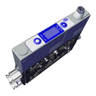
Page 12: Ejector Structure
Product description 3.4 Ejector Structure Compressed air connector (marking 1) Vacuum connection (marking 2) Operating and display elements 4.1 M8 electrical connector, 6-pole 4.2 JST electrical connector, 5-pole Optional: compressed air connector for Silencer (marking 3) external blow off EB (marking 1A) Valve screw for blow off volume flow 2x mounting hole 12 / 52... -
Page 13: Controls And Displays In Detail
Product description 3.5 Controls and Displays in Detail The ejector is fitted with the following elements to ensure simple operation: • 2 buttons on the foil keypad • A 3-digit display • 4 light-emitting diodes (LEDs) as status indicators MENU BUTTON LED B for blow off state Display LED for switching point limit value SP1... - Page 14 Product description The table below explains the meaning of the LEDs: Item Limit value LEDs Ejector state 4 and 6 LEDs both off Rising vacuum: vacuum < SP2 Falling vacuum: vacuum < rP2 4 and 6 SP2 LED lit steadily Rising vacuum: vacuum >...
-
Page 15: Technical Data
Technical Data 4 Technical Data 4.1 Display Parameters Parameter Value Unit Note Display Digit Red 7-segment LED display Resolution ±1 mbar Accuracy ±3 % FS = 25° C, based on FS final value (full-scale) Display refresh rate Only affects the 7-segment display Idle time before the The display mode is accessed automatically when no set- menu is exited... -
Page 16: Mechanical Data
Technical Data 4.4 Mechanical Data 4.4.1 Performance Data Type Nozzle 03 Nozzle 05 Nozzle 07 Nozzle 10 Nozzle size [mm] Degree of evacuation [%] Max. suction rate [l/min] Air consumption for suction [l/min] Air consumption for blow off [l/min] Sound pressure level, unobstructed suc- tion [dB(A)] Sound pressure level, suction [dB(A)] Pressure range [bar]... -
Page 17: Maximum Torque
Technical Data 17.5 Depending on the particular 12.5 ejector, see chapter 3.3 “Ejector designation” All specifications are in mm 4.4.3 Maximum Torque Connection Max. torque Mounting hole d4 1 Nm Electrical connector G3 Hand-tight 4.4.4 Pneumatic circuit plans EN-US · 30.30.01.01963 · 00 · 05/19 17 / 52... -
Page 18: Factory Settings
Technical Data NC-EB NO-EB 4.4.5 Factory Settings Code Parameter Value of the factory setting Switching point SP1 750 mbar Reset point rP1 600 mbar Switching point SP2 550 mbar Reset point rP2 540 mbar Blow off time 0 s Activated = on Control Evacuation time 0 s Leakage value 0 mbar/s Vacuum unit in mbar = bar... -
Page 19: Operating And Menu Concepts
Operating and Menu Concepts 5 Operating and Menu Concepts The ejector is operated using two buttons on the foil keypad: MENU BUTTON PLUS BUTTON Navigation is divided into three menus: • The main menu: for standard applications • The Extended Functions (EF) menu: for applications with special requirements •... -
Page 20: Displaying The Basic Settings (Slide Show)
Operating and Menu Concepts 5.1.2 Displaying the basic settings (slide show) When you press the button from the home screen, the following parameters are automatically dis- played one after the other on the display (slide show): • The vacuum unit • The value of the switching point SP1 •... -
Page 21: Extended Functions Menu (Ef)
Operating and Menu Concepts 5. Use the button to set the second digit. 6. Press the button to save the modified value. ð The second digit is accepted and the third digit flashes. 7. Use the button to set the third digit. 8. -
Page 22: Info Menu [Inf]
Operating and Menu Concepts 3. Use the button to change the value. The value increases by 1 each time the button is pressed. After 9, the counter goes back to 0 when the button is pressed. 4. Press the button to save the modified value. ð... -
Page 23: How Data Is Displayed In The Info Menu
Operating and Menu Concepts 5.4.2 How data is displayed in the info menu Counter values o r numbers with more than 3 digits are displayed in a special manner. Counter values and serial numbers are 9-digit whole numbers. These numbers are divided into 3 blocks of 3 numbers when shown on the display. -
Page 24: Description Of Functions
Description of Functions 6 Description of Functions 6.1 Overview of Functions Description Parameter See section Operating modes — (> See ch. Operating Modes, Page 24) Automatic operation and manual operation 5P1 / rP1 Switching point setting (> See ch. Monitoring the system vacuum and defin- ing limit values, Page 26) 5P2 / rP2 Calibrate zero point... - Page 25 Description of Functions In manual mode, the “suction” and “blow off” ejector functions can be controlled independently of the higher-level controller using the buttons on the foil keypad of the operating element. This function is used, among other things, to detect and eliminate leaks in the vacuum circuit. In this operating mode, the “SP1”...
-
Page 26: Monitoring The System Vacuum And Defining Limit Values
Description of Functions Activating and Deactivating Manual Blow-off ü The ejector is in “manual mode”. 4 Press and hold the button. ð The blow off LED B lights up. ð The ejector blows off as long as the button is pressed. 4 Release the button to end the blow off. -
Page 27: No Control (Continuous Suction)
Description of Functions The following operating modes can be set for the control function using the [ctr] parameter in the Ex- tended Functions menu. 6.5.1 No Control (Continuous Suction) The ejector produces continuous suction with maximum power. This setting is recommended for very por- ous workpieces, which would otherwise cause the vacuum generator to switch on and off continuously due to the high rate of leakage. -
Page 28: Reset To Factory Settings
Description of Functions Unit Explanation The setting for this unit is [iX9]. The vacuum level is displayed in psi. The setting for this unit is [P5i]. 6.8 Reset to factory settings This function is used to reset the following configurations to their factory settings: •... -
Page 29: Displaying The Software Version
Description of Functions Designation Display parameter Description Counter 1 Counter for suction cycles (suction signal input) [Cc1] Counter 2 Counter for the “suction valve” switching fre- [Cc2] quency Calling up the counter values ü Select the counter you wish to see in the system menu. 4 Confirm your selection of counter 1 [cc1] or counter 2 [cc2] using the button. -
Page 30: Displaying The Serial Number
Description of Functions The part number consists of 4 blocks with a total of 11 digits. Displayed section 02. 0 2. 0 0 Digit block The part number in this example is 10.02.02.00383. 4 To exit the function, press the button. -
Page 31: Condition Monitoring (Cm)
Description of Functions 6.13 Condition Monitoring (CM) 6.13.1 Evacuation Time Monitoring Vacuum [mbar] Start suction cycle Time [s] Measuring the evacuation time t1: The interval between reaching the switching points SP2 and SP1 is measured (in ms). The specified value for the max. permitted evacuation time can be set in the Extended Functions menu with the parameter [t-1]. -
Page 32: Leakage Monitoring
Description of Functions 6.13.2 Leakage monitoring Vacuum Time Measuring the leakage: In control mode ([ctr] = [on]), the vacuum drop/leakage over a certain period of time is measured (as vacuum drop per unit time in mbar/s) from the point when the air saving function interrupts suction after reaching switching point SP1. -
Page 33: Transport And Storage
1. Compare the entire delivery with the supplied delivery notes to make sure nothing is missing. 2. Damage caused by defective packaging or in transit must be reported immediately to the carrier and J. Schmalz GmbH. EN-US · 30.30.01.01963 · 00 · 05/19... -
Page 34: Installation
Installation 8 Installation 8.1 Installation Instructions CAUTION Improper installation or maintenance Personal injury or damage to property 4 During installation and maintenance, make sure that the ejector is disconnected and depressurized and that it cannot be switched on again without authorization. For safe installation, the following instructions must be observed: 1. -
Page 35: Pneumatic Connection
Installation The ejector is usually mounted using the holes on the side. Alternatively, it can be mounted using a DIN rail or a mounting bracket (> See ch. Accessories, Page 47): Side mounting 4 There are two 4.4 mm through-holes for mounting the ejector. Use screws at least 20 mm in length. -
Page 36: Connecting The Compressed Air And Vacuum
Installation 8.3.1 Connecting the Compressed Air and Vacuum Description of the pneumatic connection Compressed air connector (marking 1) Vacuum connection (marking 2) The threaded or push-in compressed air connector is marked with the number 1 on the ejector. 4 Connect compressed air hose. For threaded connectors, the maximum tightening torque is 1 Nm. The threaded or push-in vacuum connector is marked with the number 2 on the ejector. -
Page 37: Optional: External Blow-Off Connection (Eb)
Installation 8.3.3 Optional: External blow-off connection (EB) The ejector is also optionally available with an additional compressed air connector for the blow off func- tion. With the external blow off function (EB), the blow off pulse is controlled separately and independently of the compressed air supply for vacuum generation, allowing you to use a different medium (e.g. -
Page 38: Pin Assignments
“Suction” signal input Blue Ground Black “Parts control” output (SP2) Gray “Blow off” signal input — Pink Not used When using a Schmalz connection cable, part no. 21.04.05.00488 (see accessories) 38 / 52 EN-US · 30.30.01.01963 · 00 · 05/19... - Page 39 Installation JST socket Symbol Wire color Function Brown 24 V power supply White “Suction” signal input Blue Ground Black “Parts control” output (SP2) Gray “Blow off” signal input EN-US · 30.30.01.01963 · 00 · 05/19 39 / 52...
-
Page 40: Operation
Operation 9 Operation 9.1 General Preparations WARNING Extraction of hazardous media, liquids or bulk material Personal injury or damage to property! 4 Do not extract harmful media such as dust, oil mists, vapors, aerosols etc. 4 Do not extract aggressive gases or media such as acids, acid fumes, bases, biocides, dis- infectants or detergents. -
Page 41: Troubleshooting
Troubleshooting 10 Troubleshooting 10.1 Help with Malfunctions Malfunction Possible cause Solution 4 Make sure device is properly con- Power supply disrupted Electrical connector nected to power 4 Check electrical connection and pin No communication Incorrect electrical connection assignment 4 Check the controller configuration Higher-level controller not cor- rectly configured 4 Check electrical connection and pin... -
Page 42: Error Messages
Troubleshooting 10.2 Error messages If a known error occurs, it is reported/shown on the display. The following table shows all of the error codes: Code dis- Explanation played Zero-point adjustment of the vacuum sensor outside ± 3% FS Supply voltage is too low Supply voltage is too high Present vacuum exceeds the measurement range Overpressure in vacuum circuit, this normally happens exclusively in blow off mode. -
Page 43: Maintenance
Maintenance 11 Maintenance 11.1 Safety Maintenance work may only be carried out by qualified personnel. WARNING Risk of injury due to incorrect maintenance or troubleshooting 4 Check the proper functioning of the product, especially the safety features, after every maintenance or troubleshooting operation. NOTE Incorrect maintenance work Damage to the ejector! -
Page 44: Replacing The Silencer
Maintenance 11.3 Replacing the Silencer Heavy infiltration of dust, oil, etc. may contaminate the silencer and reduce the suction capacity. Cleaning the silencer is not recommended due to the capillary effect of the porous material. If the suction capacity decreases, replace the silencer: ü... - Page 45 Maintenance 4. Pull the filter out of the housing and dispose of it. 5. Insert the new filter into the housing and rein- stall the silencer. 6. Mount the clamp in the correct position! ð The clamp is mounted flush with the un- derside of the ejector and the clamp legs both lie in the grooves.
-
Page 46: Warranty
Warranty 12 Warranty This system is guaranteed in accordance with our general terms of trade and delivery. The same applies to spare parts, provided that these are original parts supplied by us. We are not liable for any damage resulting from the use of non-original spare parts or accessories. The exclusive use of original spare parts is a prerequisite for the proper functioning of the ejector and for the validity of the warranty. -
Page 47: Spare And Wearing Parts, Accessories
Spare and Wearing Parts, Accessories 13 Spare and Wearing Parts, Accessories 13.1 Spare and Wearing Parts Maintenance work may only be carried out by qualified personnel. WARNING Risk of injury due to incorrect maintenance or troubleshooting 4 Check the proper functioning of the product, especially the safety features, after every maintenance or troubleshooting operation. -
Page 48: Decommissioning And Recycling
Decommissioning and recycling 14 Decommissioning and recycling 14.1 Disposing of the Ejector 1. Dispose of the product properly after replacement or decommissioning. 2. Observe the country-specific guidelines and legal obligations for waste prevention and disposal. 14.2 Materials Used Component Material Housing PA6-GF Inner components Aluminum alloy, anodized aluminum alloy, stainless steel, POM Controller housing PC/ABS... -
Page 49: Appendix
Appendix 15 Appendix 15.1 Overview of Display Codes Display Parameter Comment code Switching point 1 Value at which the control function deactivates Reset point 1 Reset value 1 for the control function Switching point 2 Activation value of “Parts control” signal output Reset point 2 Reset value 2 for the “Parts control”... -
Page 50: Ec Declaration Of Conformity
Appendix 15.2 EC declaration of conformity EC Declaration of Conformity The manufacturer Schmalz confirms that the Ejector described in these operating instructions fulfill the following applicable EC directives: 2014/30/EU Electromagnetic Compatibility 2011/65/EU Directive on the restriction of the use of certain hazardous substances in... - Page 51 30.30.01.01963 · 00 · 05/19 51 / 52...
Need help?
Do you have a question about the Compact Ejector SCPMc and is the answer not in the manual?
Questions and answers