
Related Manuals for Schmalz SCPi FS RP


Summary of Contents for Schmalz SCPi FS RP
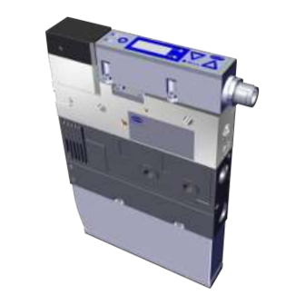
- Page 1 Compaktejector SCPi FS RP Operating Instructions WWW.SCHMALZ.COM EN-US · 30.30.01.01602 · 01 · 10/18...
- Page 2 Published by © J. Schmalz GmbH, 10/18 This document is protected by copyright. J. Schmalz GmbH retains the rights established thereby. Repro- duction of the contents, in full or in part, is only permitted within the limits of the legal provisions of copyright law. Any modifications to or abridgments of the document are prohibited without explicit writ- ten agreement from J. Schmalz GmbH.
-
Page 3: Table Of Contents
Contents Contents 1 Important information ........................... 7 1.1 Note on using these operating instructions .................. 7 1.2 The technical documentation is part of the product ................ 7 1.3 Warnings in this document........................ 7 1.4 Symbol.............................. 7 2 Fundamental Safety Instructions........................ 8 2.1 Standards of Technology ........................ 8 2.2 Emissions .............................. - Page 4 Contents 4.4.4 Pneumatic Circuit Plan ...................... 17 5 General Description of Functions ........................ 18 5.1 Digital Switching Outputs (SIO)...................... 18 5.2 IO-Link.............................. 18 5.3 Operating and Menu Concepts ...................... 19 5.3.1 Navigating in the Menu ...................... 19 5.3.2 Enabling Vacuum Switches and Editing Parameters ............... 19 5.3.3 Displaying the Basic Settings (Slide Show)................
- Page 5 Contents 8.3.4 Condition Monitoring Mode (Leakage Measurement)............ 33 8.3.5 Diagnostics Mode ........................ 34 8.4 Teach-in for Switching Points ...................... 34 8.5 Additional Switching Point Settings .................... 35 8.5.1 Switch-on and Switch-off Delay .................... 35 8.5.2 Transistor Function ........................ 35 8.6 Display Screen............................ 35 8.6.1 Vacuum Unit ..........................
- Page 6 Contents 11.1 Safety .............................. 44 11.2 Cleaning the Ejector.......................... 44 11.3 Replacement of the Device with a Parameterization Server............. 44 12 Warranty................................ 46 13 Spare and Wearing Parts, Accessories...................... 47 13.1 Spare and Wearing Parts ........................ 47 13.2 Accessories ............................ 47 14 Decommissioning and recycling ........................ 48 14.1 Disposing of the Ejector........................
-
Page 7: Important Information
3. Pass on the technical documentation to subsequent users. ð Schmalz is not liable for damage or malfunctions that result from failure to heed these instructions. If you still have questions after reading the technical documentation, contact the Customer Service Center www.schmalz.com/services... -
Page 8: Fundamental Safety Instructions
4 Do not extract aggressive gases or media such as acids, acid fumes, bases, biocides, dis- infectants or detergents. 4 Do not extract liquids or bulk materials, e.g. granulates. Schmalz accepts no liability for damages caused by non-intended usage of the ejector. In particular, the following are considered non-intended use: •... -
Page 9: Personnel Qualification
Technically trained persons who work on electrical equipment 2.6 Modifications to the Ejector Schmalz assumes no liability for consequences of modifications over which it has no control: 1. The ejector must be operated only in its original condition as delivered. 2. Use only original spare parts from Schmalz. -
Page 10: Product Description
Product description 3 Product description 3.1 Description of the Ejector 3.1.1 Suction of the Workpiece (Vacuum Generation) The Venturi nozzle on the ejector is activated and deactivated using the Suction command. In the NO (normally open) version, the Venturi nozzle is continuously sucking. As soon as compressed air is present at the ejector, the Venturi nozzle becomes active and the ejector generates a vacuum (suction). -
Page 11: Pneumatic Air Saving Function
Product description 3.1.3 Pneumatic Air Saving Function The ejector includes a pneumatically operated air saving function. When compressed air is applied to com- pressed air connection 1 (> See ch. (See chap. Ejector structure)), the ejector automatically controls the vacuum. When the set deactivation value A is reached, the ejector switches off the Venturi nozzle. If the system vacuum drops below the activation value E due to leaks, the Venturi nozzle is switched back on. -
Page 12: Ejector Structure
Product description 3.4 Ejector Structure Silencer Type plate 1 4x mounting holes Position of pneumatic controller Vacuum switch with control and display el- Electrical connection, M12, 5-pin ement Compressed air connection 1A (blow off) Compressed air connection 1 (suction) Bypass for exhaust air Type plate 2 Vacuum connection 12 / 58... -
Page 13: Display And Operating Element In Detail
Product description 3.5 Display and Operating Element in Detail The simple operation of the vacuum switch is ensured by 3 buttons, the 3-digit display, as well as 2 LEDs for status information. Menu button Display LED switching point 1 Down button Up button LED switching point 2 Switching points are indicated using two orange LEDs. -
Page 14: Technical Data
Technical Data 4 Technical Data 4.1 Display Parameters Parameter Value Unit Note Display Digit Red 7-segment LED display Resolution ±1 mbar — Accuracy ±3 % FS = 25° C, based on FS final value (full-scale) Linearity error ±1 — Offset error ±2 mbar After zero-point adjustment, without vacuum Temperature influ-... -
Page 15: General Parameters
Technical Data 4.3 General Parameters Parameter Symbol Limit value Unit Note min. typ. max. Working temperature — °C — Storage temperature — °C — Humidity — % r.h. Free from condensation Degree of protection — — — IP65 — — Operating pressure —... -
Page 16: Dimensions
Technical Data Display code Parameter Value of the factory setting Window hysteresis 1 20 mbar Switch-on delay 1 0 ms Switch-off delay 1 0 ms Window hysteresis 2 100 mbar Switch-on delay 2 0 ms Switch-off delay 2 0 ms PNP switch = P-n Signal type / transistor function Vacuum unit in mbar = -bA Vacuum unit Deactivated = oFF... -
Page 17: Pneumatic Circuit Plan
Technical Data 4.4.4 Pneumatic Circuit Plan EN-US · 30.30.01.01602 · 01 · 10/18 17 / 58... -
Page 18: General Description Of Functions
General Description of Functions 5 General Description of Functions 5.1 Digital Switching Outputs (SIO) To operate the standard digital inputs of the automation technology or to directly control the electrical consumers, the switch has two digital outputs. In the delivery state, the signal output OUT 1 is assigned the function switching point 1, parts control, and the signal output OUT 2 is assigned the switching point 2, leakage monitoring. -
Page 19: Operating And Menu Concepts
General Description of Functions 5.3 Operating and Menu Concepts The unit is operated via three buttons on the foil keypad. The parameters are set via software menus. The current system status and the settings are shown on a display. The operating structure is divided into three menus: •... -
Page 20: Displaying The Basic Settings (Slide Show)
General Description of Functions 3. Confirm using the button ð The display changes to the middle digit. 4. Enter the remaining digits in the same way. 5. To enable the device using the menu, press the button ð When entering a valid PIN the message VnC appears. ð... -
Page 21: Basic Menu
General Description of Functions 5.3.4 Basic Menu All of the settings for standard vacuum switch applications can be configured and read from the basic menu. 1. Use to select the desired adjustable parameter. 2. Confirm the selection of the parameter with the button. -
Page 22: Extended Functions Menu (Ef)
General Description of Functions 5.3.5 Extended Functions Menu (EF) An "Extended functions" menu (EF) is available for applications with special requirements. button to select the EF parameter and change to the param- 1. In the basic menu, press the eter selection of the EF menu by pressing the button. -
Page 23: Info Menu (Inf)
General Description of Functions 5.3.6 Info menu (INF) The "Info" (INF) menu is available for reading out system data such as counters, software version, part numbers and serial numbers. button to select the 1mF parameter and change to the pa- 1. In the basic menu, press the rameter selection of the menu by pressing the button. -
Page 24: Error Display
General Description of Functions Prompting for the part number The part number of the ejector is printed on the label and also stored electronically. After confirming the part number Art parameter with the button, the first two digits of the part number are displayed. -
Page 25: Transport And Storage
1. Compare the entire delivery with the supplied delivery notes to make sure nothing is missing. 2. Damage caused by defective packaging or in transit must be reported immediately to the carrier and J. Schmalz. EN-US · 30.30.01.01602 · 01 · 10/18... -
Page 26: Installation
Installation 7 Installation 7.1 Installation Instructions CAUTION Improper installation or maintenance Personal injury or damage to property 4 During installation and maintenance, make sure that the ejector is disconnected and depressurized and that it cannot be switched on again without authorization. For safe installation, the following instructions must be observed: 1. -
Page 27: Pneumatic Connection
Installation For start of operations, the ejector must be connected to the controller via the connection plug with a connection cable. The compressed air required to generate the vacuum and the blow off is connected via the corresponding compressed air connections. The compressed air supply must be supplied by the higher- level machine. -
Page 28: Instructions For The Pneumatic Connection
Installation 4 Connect compressed air hose. The max. tightening torque is 10 Nm. The compressed air connection 1A on the ejector has the size G1/8"-IG. 4 Connect compressed air hose. The max. tightening torque is 10 Nm. The vacuum connection G3/8"-IG is marked with the number 2 on the ejector. 4 Connect vacuum hose. - Page 29 Installation NOTE Incorrect power supply Destruction of the integrated electronics 4 Operate the product using a power supply unit with protected extra-low voltage (PELV). 4 The system must incorporate safe electrical cut-off of the power supply in compliance with EN60204. 4 Do not connect or disconnect the connector under tension and/or when voltage is ap- plied.
-
Page 30: Operating The Vacuum Switch In Sio Mode
Using the Schmalz connection cable, part no. 21.04.05.00080, with connector M12-5 with open end and 5 m length. 2. Connection via an I/O box Using the Schmalz connection cable, part no. 21.04.05.00158, with connector M12-5 on M12-5 and 1 m length. 7.4.2 Operating the Vacuum Switch in IO-Link Mode... -
Page 31: Functions Of The Vacuum Switch
Functions of the Vacuum Switch 8 Functions of the Vacuum Switch 8.1 Overview of Functions Description Availability Parameter See section IO-Link 5P1 / FX1 Switching point setting (> See ch. 8.3.) rP1 / FL1 hy1 / L-1 5P2 / FX2 rP2 / FL2 hy2 / L-2 0u1 / 0u2 Switching point mode and logic... -
Page 32: Monitoring The Operating Voltage
Functions of the Vacuum Switch 8.2 Monitoring the Operating Voltage The vacuum switch measures the amount of its operating voltage US with a resolution of 100 mV. When the valid voltage range is left, corresponding error statuses (> See ch. 10.2 and 10.3) are triggered. In the undervoltage range, the switch delays all inputs by the user. -
Page 33: Window Mode
Functions of the Vacuum Switch Pressure p [mbar] Switching point SP Reset point rP Time t Output NO Output NC 8.3.3 Window Mode In window mode, the switching point is active when the measurement value is between the upper win- dow point FHx and the lower window point FLx. Outside this window, the switching point is inactive. If necessary, a common switching hysteresis Hyx can be set, which symmetrically applies to both window points. -
Page 34: Diagnostics Mode
Functions of the Vacuum Switch The detection of an external suction cycle is carried out using the adjustable limit values SPx and rPx that indicate the limits for picking up and depositing a workpiece. The threshold for the maximum permissible leakage is set using the parameter L-x in millibars per second. -
Page 35: Additional Switching Point Settings
Functions of the Vacuum Switch 8.5 Additional Switching Point Settings 8.5.1 Switch-on and Switch-off Delay For each switching point and each associated limit value, a delay time can be set, with the exception of condition monitoring mode. Here, this parameter can only be defined for the switching point SP1. In Con- dition monitoring mode, the parameters dSx and drx are also not shown on the display. -
Page 36: Display Alignment
Functions of the Vacuum Switch 8.6.2 Display Alignment The display alignment can be rotated by 180 degrees using the parameter di5 to adapt to the installa- tion position of the ejector. When rotated, the decimal point on the far right is no longer displayed and is therefore missing from the display of the counter statuses and serial numbers. -
Page 37: Device Identification
Functions of the Vacuum Switch A menu lock using the Device access locks parameter has a higher priority than the menu PIN. In other words, this lock cannot be bypassed by entering a PIN and remains in SIO mode. It can only be canceled via IO-Link, not via the ejector or the vacuum switch itself. 8.8 Device Identification The IO-Link protocol provides a range of identification data for compliant devices that can be used to uniquely identify a device. -
Page 38: Status Signals
Functions of the Vacuum Switch The average switching frequency of the air saving function can be determined using the difference be- tween counters 1 and 2. The erasable counters ct1 and ct2 can be reset to 0 during operation via IO-Link by using the appropriate system commands. -
Page 39: Calibrating The Vacuum Sensor
Functions of the Vacuum Switch The Reset to factory settings function does not affect: • Counter statuses • The zero-point adjustment of the sensor • The maximum and minimum values of the measurements 8.11.2 Calibrating the Vacuum Sensor As the production conditions for the internally integrated vacuum sensor can vary, we recommend cali- brating the sensor once it is installed in the ejector. -
Page 40: Operation
Operation 9 Operation 9.1 General Preparations WARNING Extraction of hazardous media, liquids or bulk material Personal injury or damage to property! 4 Do not extract harmful media such as dust, oil mists, vapors, aerosols etc. 4 Do not extract aggressive gases or media such as acids, acid fumes, bases, biocides, dis- infectants or detergents. -
Page 41: Troubleshooting
Troubleshooting 10 Troubleshooting 10.1 Help with Malfunctions Error Cause Measure Master or peripheral Connection to IO-Link master with 4 Connection to IO-Link class A port power supply disturbed IO-Link class-B port 4 Check electrical connection and PIN No output signal Incorrect electrical connection assignment 4 Adjust the transistor function (PNP/ Transistor function (PNP/NPN) not... -
Page 42: List Of Error Numbers
Troubleshooting Error Cause Measure Limit values SPx and rPx for leak- 4 Set limit values in such a way that age measurement set too high there is a clear differentiation be- tween the neutral and suction sys- tem statuses 10.2 List of Error Numbers When a known error occurs, this is reported in the form of an error number. -
Page 43: Warnings And Error Messages In Io-Link Mode
Troubleshooting Display code Fault Possible cause Measure Teach-in er- Teach-in was carried out with in- 4 Measurement value must be in valid measured value (FFF/-FF), the valid measurement range teach-in of the leakage mode was carried out with existing pressure Measure- Overpressure in the system, e.g. -
Page 44: Maintenance
Maintenance 11 Maintenance 11.1 Safety Maintenance work may only be carried out by qualified personnel. WARNING Risk of injury due to incorrect maintenance or troubleshooting 4 Check the proper functioning of the product, especially the safety features, after every maintenance or troubleshooting operation. NOTE Incorrect maintenance work Damage to the ejector! - Page 45 Maintenance Use the Parameterization server function of the IO-Link master to ensure that no data is lost when switching the device. EN-US · 30.30.01.01602 · 01 · 10/18 45 / 58...
-
Page 46: Warranty
Warranty 12 Warranty This system is guaranteed in accordance with our general terms of trade and delivery. The same applies to spare parts, provided that these are original parts supplied by us. We are not liable for any damage resulting from the use of non-original spare parts or accessories. The exclusive use of original spare parts is a prerequisite for the proper functioning of the ejector and for the validity of the warranty. -
Page 47: Spare And Wearing Parts, Accessories
Spare and Wearing Parts, Accessories 13 Spare and Wearing Parts, Accessories 13.1 Spare and Wearing Parts Maintenance work may only be carried out by qualified personnel. WARNING Risk of injury due to incorrect maintenance or troubleshooting 4 Check the proper functioning of the product, especially the safety features, after every maintenance or troubleshooting operation. -
Page 48: Decommissioning And Recycling
Decommissioning and recycling 14 Decommissioning and recycling 14.1 Disposing of the Ejector 1. Dispose of the product properly after replacement or decommissioning. 2. Observe the country-specific guidelines and legal obligations for waste prevention and disposal. 14.2 Materials Used Component Material Housing PA6-GF, PC-ABS, AL Inner components Aluminum alloy, anodized aluminum alloy, brass, galvanized steel, stainless- steel, PU, POM... -
Page 49: Appendix
Appendix 15 Appendix See also 2 SCPi_CE_30.30.01.01667-00.pdf [} 50] 2 SCPi_Data Dictionary_01.pdf [} 51] EN-US · 30.30.01.01602 · 01 · 10/18 49 / 58... - Page 51 IO-Link Data Dictionary SMP FS RP 21.10.01.00115/00 13.03.2018 J. Schmalz GmbH Aacher Straße 29, D 72293 Glatten Tel.: +49(0)7443/2403-0 Fax: +49(0)7443/2403-259 info@schmalz.de IO-Link Implementation Vendor ID 234 (0x00EA) Device ID 100244 (0x018794) SIO-Mode IO-Link Revision 1.1 (compatible with 1.0) IO-Link Profile...
- Page 52 IO-Link Data Dictionary SMP FS RP 21.10.01.00115/00 13.03.2018 J. Schmalz GmbH Aacher Straße 29, D 72293 Glatten Tel.: +49(0)7443/2403-0 Fax: +49(0)7443/2403-259 info@schmalz.de IO-Link Implementation ISDU Parameters ISDU Index Subindex Display Parameter Size Value Range Access Default Value Remark Appearance ...
- Page 53 IO-Link Data Dictionary SMP FS RP 21.10.01.00115/00 13.03.2018 J. Schmalz GmbH Aacher Straße 29, D 72293 Glatten Tel.: +49(0)7443/2403-0 Fax: +49(0)7443/2403-259 info@schmalz.de IO-Link Implementation Parameter Device Settings Commands 0x05 (dec 5): Force upload of parameter data into the master...
- Page 54 IO-Link Data Dictionary SMP FS RP 21.10.01.00115/00 13.03.2018 J. Schmalz GmbH Aacher Straße 29, D 72293 Glatten Tel.: +49(0)7443/2403-0 Fax: +49(0)7443/2403-259 info@schmalz.de IO-Link Implementation Process Settings Switch Point 1 0x003C SP1/FH1 Switch Point 1 - Upper Threshold 2 bytes...
- Page 55 IO-Link Data Dictionary SMP FS RP 21.10.01.00115/00 13.03.2018 J. Schmalz GmbH Aacher Straße 29, D 72293 Glatten Tel.: +49(0)7443/2403-0 Fax: +49(0)7443/2403-259 info@schmalz.de IO-Link Implementation Observation Monitoring Process Data 0x0028 Process Data In Copy 2 bytes Copy of currently active process data input...
- Page 56 IO-Link Data Dictionary SMP FS RP 21.10.01.00115/00 13.03.2018 J. Schmalz GmbH Aacher Straße 29, D 72293 Glatten Tel.: +49(0)7443/2403-0 Fax: +49(0)7443/2403-259 info@schmalz.de IO-Link Implementation Parameter ISDU 138 - Extended Device Status Type Type Color Type Text Status Text 0x10 Green...
-
Page 57: Notes
Notes 16 Notes EN-US · 30.30.01.01602 · 01 · 10/18 57 / 58...
Need help?
Do you have a question about the SCPi FS RP and is the answer not in the manual?
Questions and answers