
Subscribe to Our Youtube Channel
Related Manuals for Hanna Instruments HI6321


Summary of Contents for Hanna Instruments HI6321
- Page 1 INSTRUCTION MANUAL HI6321 Advanced Conductivity Benchtop Meter Hanna Instruments Inc., 584 Park East Drive, Woonsocket, RI 02895 USA www.hannainst.com...
-
Page 2: Table Of Contents
All rights are reserved. Reproduction in whole or in part is prohibited without the written consent of the copyright owner, Hanna Instruments Inc., Woonsocket, Rhode Island, 02895, USA. Hanna Instruments reserves the right to modify the design, construction, or appearance of its products without advance notice. -
Page 3: Preliminary Examination
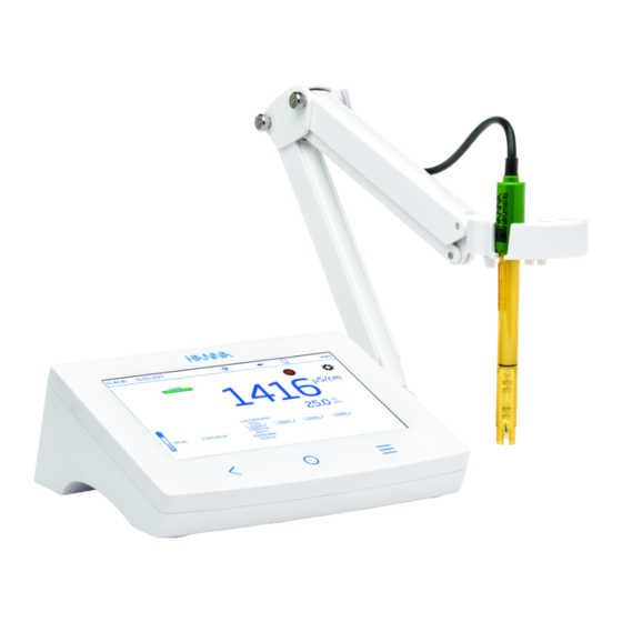
Preliminary Examination 1. PRELIMINARY EXAMINATION HI6321 is Hanna’s advanced benchtop conductivity meter with a large touch screen display and streamlined design. ® Each HI6321 is supplied with: • HI7631233 EC and resistivity probe • HI764060 electrode holder with following accessories: base plate (with integrated pivot pin) and screw (requires installation) •... -
Page 4: User Interface - Icons
User Interface – Icons 3. USER INTERFACE – ICONS Capacitive keys Description Back – return to a previous hierarchical menu level Home – access to measurement screen & configured profile Menu – access to Users, System Settings, Measurement Settings, Log Recall, Help Main menu Description Users –... - Page 5 User Interface – Icons Log recall Description Table view – function active / not selected Graph view – function active / not selected Information view – function active / not selected General Description Measurement profile Background operation in progress Active alarm set Stability / Autohold indicator Unstable Stable...
-
Page 6: General Description & Intended Use
General Description & Intended Use 4. GENERAL DESCRIPTION & INTENDED USE HI6321 is an advanced benchtop meter with a capacitive display, comprised of a housing and an integrated conductivity measurement module. Compact and easy to operate, the meter is delivered with HI7631233 EC and resistivity probe. - Page 7 General Description & Intended Use Main Features Calibration & Measurement • Measure ` Conductivity – μS/cm or mS/cm ` Resistivity – Ω cm , kΩ cm, MΩ • • • ` TDS – ppm or ppt ` Salinity – ppt, PSU, % •...
-
Page 8: Specifications
Specifications 5. SPECIFICATIONS 5.1. INSTRUMENT 0.000 to 9.999 μS/cm 10.00 to 99.99 μS/cm 100.0 to 999.9 μS/cm Range 1.000 to 9.999 mS/cm 10.00 to 99.99 mS/cm 100.0 to 1000.0 mS/cm 0.001 μS/cm 0.01 μS/cm 0.1 μS/cm Resolution 0.001 mS/cm 0.01 mS/cm 0.1 mS/cm Accuracy ±1 % of reading or ±0.010 μS/cm, whichever is greater... - Page 9 9 Specifications 1.0 to 99.9 Ω • 100 to 999 Ω • 1.00 to 9.99 KΩ • Range 10.0 to 99.9 KΩ • 100 to 999 KΩ • 1.00 to 9.99 MΩ • 10.0 to 100.0 MΩ • Resistivity 0.1 Ω •...
- Page 10 Specifications Range −20.0 to 120.0 °C / −4.0 to 248.0 °F / 253.2 to 393.2 K Resolution 0.1 °C / 0.1 °F / 0.1 K Temperature Accuracy ±0.2 °C / ±0.4 °F / ±0.2 K Calibration Single point, adjustable Direct Modes Direct/Autohold Accurate...
-
Page 11: Hi7631233 Probe
11 Specifications 5.2. HI7631233 PROBE Range 0 to 1000 mS/cm Recommended operating temperature −5 to 100 °C (23 to 212 °F) Temperature sensor Built‑in Cell constant 1 ± 15 % Cell type Four‑ring, platinum on glass Body Polyetherimide (PEI) Sensor body PVDF Wetted parts O‑ring Sensor diameter... -
Page 12: Functional & Lcd Description
Functional & LCD Description 6. FUNCTIONAL & LCD DESCRIPTION 6.1. MAIN UNIT Front View 1. LCD display 3. Home key 2. Back key 4. Menu key LCD Description 1. Current time 9. Temperature reading 2. Current date and temperature compensation status 3. Stability statusr 10. - Page 13 Back • exit or escape function • access to measurement screen Home • exit or escape function • access to Users, System Settings, Measurement Settings, Log Recall, Help Menu Rear View HI6321 Conductivity USB-C USB-A Ethernet ON/OFF Power Extension 24Vdc 1.
-
Page 14: Probe
Functional & LCD Description 6.2. PROBE HI7631233 four‑ring conductivity probe provides stable measurements over a wide measure range and does not require frequent calibrations. An integral temperature sensor measures temperature and adjusts the measured conductivity to a reference temperature by applying compensation standards. 1 Cable 2 Probe body 3 Probe holes... -
Page 15: Getting Started
15 Getting Started 7. GETTING STARTED 7.1. INSTALLING THE HOLDER Attaching the base plate • Take the HI764060 holder from the box. • Identify the metal base plate (4) with the integrated pivot pin (5) and the screw (2). • The plate may be attached to either side of the meter, left (L) or right (R). •... -
Page 16: Using The Holder
Hanna aims to ensure meter compatibility with USB printers but can not ensure compatibility with all models. ® HI6321 can print directly to certain models of USB‑dedicated printers with PCL printer language capability. Printer components and requirements • Printer, PCL driver compatible •... -
Page 17: Language And Regional Preferences
17 Getting Started 7.4. POWERING THE UNIT & SELECTING OPERATING LANGUAGE AND REGIONAL PREFERENCES 1. Connect the power adapter to the rear panel of the meter. 2. Connect the power plug into the 24 V power socket. 3. Press the black ON/OFF power button. At start up, the meter briefly displays the initialization screen. -
Page 18: System Menu Items
System Menu Items 8. SYSTEM MENU ITEMS (direct Menu key) to access System Menu screen. Users must have previously logged in. System Menu capacitive icons Symbol Name Functionality Users Login and rights configuration & instrument accessibility System Settings System configuration, connectivity, and printing items Measurement Settings Measurement configuration Log Recall... - Page 19 19 System Menu Items On first access, “Admin” is default user name and no password is required. Default options are updated from the Users menu. Function Administrator* Standard User Enable account creation – Reset password – Delete account – Assign administrator rights –...
- Page 20 System Menu Items 9. Enter password and tap . Reenter password to confirm. Log Out & Switch User 1. Tap followed by Logout. 2. Tap user’s account avatar. 3. Input password. Adding & Removing Users (users with administrator rights only) 1. Tap followed by 2.
- Page 21 21 System Menu Items Account Management Users with administrator rights are able to: • Enable Account Creation • Enable Logins Each power up requires user selection before instrument enters measurement mode. • Enable Admin i.e. assign administrator rights to a standard user •...
-
Page 22: System Settings
System Menu Items 8.2. SYSTEM SETTINGS System Settings is the second item under the System Menu. Network, Connect & Print, System tabs permit users to navigate system settings and operations, configure network connection and architecture, connectivity and printing services, change system settings, and view meter information. - Page 23 23 System Menu Items Network Data sharing options: Ethernet, Wi-Fi, or Disabled With connection established, IP assignment can be set as: • Dynamic – IP Address, Gateway, Netmask, DNS Server are auto assigned • Static – network details are entered manually To input network information: 1.
- Page 24 System Menu Items Connect & Print Options: Connectivity, Printer Connectivity to enable (disable) following connectivity options: • FTP access to meter: log file transfer to an FTP site and meter FTP server connection to client (log download) • Meter web server: log file download to a web client •...
- Page 25 25 System Menu Items System Options: Time, Date, Language, Meter ID, Decimal Separator, Backlight Saver, Beepers, Startup Tutorial, Factory Settings, Reset User Note: Use the scroll bar to view or select from entire settings list. Time & Date to enable (disable): • Set Automatically (meter must be connected to the internet) ` Direct selection from scrollable list of options ` UTC options: from UTC 00:00 to UTC+14:00...
- Page 26 System Menu Items Meter ID • Name the meter with a discrete name, location, or number. • Tap to save. Note: option available to users with administrator rights only. or corresponding tab to enable (disable) following settings: Decimal Separator: comma or period depending on regional preference Backlight Saver: enabled, 1 to 60 minutes (or disabled) If the backlight turns off after the set period of time, tap screen to turn it back on.
-
Page 27: Measurement Settings
27 System Menu Items Reset User Option restores default settings for this user. All data (including profiles and log files) specific to this user will be permanently deleted, except for the username and password. When option invoked, the instrument asks for confirmation. Info Read‑only item displays information on meter, channel serial number, and Wi‑Fi firmware version. - Page 28 System Menu Items Measurement Setup Overview Calibration, Reading, Temperature, View, Alarms, Logging, Profile tabs help user navigate through all measurement operations. The following table presents an overview of possible functions. Calibration Salinity Conductivity Resistivity ppt, PSU Calibrate Based on Based on Calibrate Based on Last Calibration Clear...
- Page 29 29 System Menu Items View Salinity Conductivity Resistivity ppt, PSU Basic Basic Basic Basic Basic Simple GLP Simple GLP Simple GLP Simple GLP Graph View Type Full GLP Graph Graph Full GLP Table Graph Table Table Graph Table Table Alarms Conductivity Resistivity Salinity 0.000 to 8.000E+1 ppt 0.000 to...
-
Page 30: Log Recall
System Menu Items 8.4. LOG RECALL Log Recall is the fourth item under the System’s Menu and allows data selection, viewing, sharing, and deletion. Logged data is retrieved by the user that has logged the measurement. • Data is stored in parameter‑specific .CSV files: conductivity, resistivity, TDS, salinity. •... - Page 31 31 System Menu Items 4. Tap icon to have logged data displayed in tabulated form or plotted. icon and scroll through USER, LOG, CHANNEL, INSTRUMENT, GLP DATA information.
- Page 32 System Menu Items Select (Deselect) All To export to a USB‑A flash drive: 1. Tap (Log Recall) to access the log history. 2. Tap Select All button to select entire log history. With all files selected, tap Delete to empty the log or tap Share to transfer data. 3.
- Page 33 System Menu Items HI6321 can act as an FTP server (host) or client. Meter has to be connected to the internet and Allow FTP access to meter enabled. See System Settings section, Connect & Print tab. • Use meter’s IP address and password to connected and view logged files.
- Page 34 System Menu Items 5. Click Next. 6. In the Binding and SSL Settings window keep all default settings but change the SSL option to No SSL. 7. Click Next. 8. When prompted to authenticate and authorize information, select Basic and Specified users. 9.
- Page 35 System Menu Items Print • Connect either a printer (Network or USB) or plug‑in a USB Flash Drive (see System Settings, Connect & Print section). • Tap Print and follow on‑screen instructions. Web server Any browser can be used to access the web server and download log files. Meter has to be connected to the internet and Enable meter web server enabled (see System Settings, Connect &...
-
Page 36: Help
System Menu Items 8.5. HELP Help is the fifth item under the System Menu. • Tap to access support and navigate through an overview of system’s main functionalities. • Tap to play (stop) video‑supported segments: ` 1.5. Setting up the device ` 3.1. -
Page 37: Measurement & Probe Setup Menu
Measurement & Probe Setup Menu 9. MEASUREMENT & PROBE SETUP MENU From the Measurement screen, tap to access system and measurement configuration tabs. Alternatively, tap (Menu key) then 9.1. CALIBRATION Options: Conductivity & Salinity Last Calibration, Standard Entry Type, Calibration Reminder, Cell Constant, Calibration Points Last Calibration (Conductivity and Salinity): Calibrate or Clear a previous calibration Standard Entry Type •... -
Page 38: Reading
Measurement & Probe Setup Menu Cell Constant: allows users to adjust cell measurement to compensate for the measured properties. • Tap dedicated field and enter value. • Tap to save. Calibration Points: allows users to select a Single Point or Multiple Points calibration. 9.2. READING Options: Parameter, Units/Salinity Scale, TDS Factor, Stability Criteria, Reading Mode, Probe Type Parameter Options: Conductivity, Resistivity, TDS, Salinity... - Page 39 Measurement & Probe Setup Menu • TDS Options: ppm, ppt, AutoRanging i.e. meter automatically selects the unit to optimize the measurement. • Salinity scale: ppt (Natural Sea Water 1966), PSU (Practical Scale 1978), %(Percent Scale) Salinity value is determined based on selected scale. TDS Factor TDS factor is a conversion factor used to change an EC measurement to a ppm measurement.
-
Page 40: Temperature
Measurement & Probe Setup Menu ` Configured parameter icon is displayed i.e. is displayed blinking until the measurement is stable. Autohold ` When stable, the indicator stops blinking and measurement freezes at current value. ` Tap parameter icon to return to direct measurement. 9.3. TEMPERATURE Options: Temperature Source, Temperature Unit, Temperature Compensation, Manual, Reference Temperature, Temperature Coefficient, User Temperature Calibration Temperature Source: Automatic, Manual... - Page 41 41 Measurement & Probe Setup Menu Temperature Unit: Celsius, Fahrenheit, Kelvin degrees Temperature Compensation (Scale): Linear, Natural, Standard • Linear: used when it is assumed that the temperature coefficient of variation has the same value for all measurement temperatures. • Natural: for natural ground, well, or surface water and covers 60 to 1000 μS/ cm (0 to 35 °C) range. •...
-
Page 42: View
Measurement & Probe Setup Menu 4. Tap Save to confirm and save the calibration data. 9.4. VIEW Conductivity, Salinity %: Basic, Simple GLP, Full GLP, Graph, Table Resistivity, TDS, Salinity ppt & PSU: Basic, Simple GLP, Graph, Table • Select preferred display configuration from View Type window. - Page 43 Measurement & Probe Setup Menu Basic Screen displays the measured value, measurement unit, stability and temperature compensation status/source. Simple GLP Simple GLP screen displays last calibration date and time, offset value and cell constant (as well as data displayed in Basic screen). Note: If no calibration was made, “Not Calibrated”...
- Page 44 Measurement & Probe Setup Menu Full GLP Full GLP screen displays probe symbol, calibration temperature, calibration information (as well as data displayed in Simple GLP screen). Graph When Graph is selected the measured value is plotted as a graph. To zoom in on a graph: 1.
-
Page 45: Alarms
Measurement & Probe Setup Menu Table When Table is selected, the measured values are displayed tabulated (complete with date, time, and notes made during logging). The newest data is displayed at the top of the table. 9.5. ALARMS Options: High /Low configured parameter value, High/Low Temperature Users can set the threshold limits for the measured parameters. -
Page 46: Logging
Measurement & Probe Setup Menu (alarm icon) is displayed on the measurement screen when an alarm is active. 9.6. LOGGING Options: Logging Type, Sampling Period, File Name, Log Note, Log Info, Sample ID Logging Type • Automatic: data is logged automatically at predefined time intervals (i.e. Sampling Period). ` A file name is automatically generated, complete with year/month/day, and logging time. -
Page 47: Profiles
Measurement & Probe Setup Menu File Name Available only with Manual and Autohold logging type selected. To create a file name, from Logging screen: 1. Tap Create. 2. Use the on‑screen keypad to enter file name (maximum 13 characters). 3. Tap Enter to confirm. Log Note &... -
Page 48: Calibration
Calibration 3. Start measuring. 10. CALIBRATION Overview of calibration icons 1 Calibration type 2 Cell constant value 3 Calibration points 4 Save and Confirm standards, calibration procedure 5 Calibration information i.e. used standard (tray), date, time 6 Probe symbol with offset and cell constant... -
Page 49: Conductivity Calibration
Calibration 10.1. CONDUCTIVITY CALIBRATION HI6321 meter allows two types of calibration procedures: • Standard up to four‑point conductivity calibration with standards for cell factor determination: ` 0 μS/cm for offset ` 84 μS/cm, 1413 μS/cm, 5.0 mS/cm,12.88 mS/cm for the 0.1/cm cell ` 80.0 mS/cm, 111.8 mS/cm additional standards for the 1.0/cm cell... - Page 50 Calibration With the probe connected to the meter: 1. From Measurement screen, tap (Measurement Menu icon). 2. Tap Temperature tab. 3. Configure Temperature Source. 4. Tap Calibration tab. 5. Configure Standard Entry Type as Automatic. 6. Select number of calibration points. 7.
-
Page 51: Salinity Calibration
51 Calibration Manual Calibration With option selected, users have to option to edit calibration point values. 1. Follow Automatic Calibration procedure up to step 9 but configure Standard Entry Type (Step 5) as Manual. 2. Suspend the probe in the air. Allow for the reading to stabilize. 3. -
Page 52: Measurement
Measurement 11. Tap Save to have calibration accepted and saved, and return to calibration setting screen. 11. MEASUREMENT Options: Direct, Direct/Autohold • Direct: sample measurements are displayed continuously. • Direct/Autohold: reading is displayed when measurement stability is reached. A measurement that has not reached equilibrium will not be used. -
Page 53: Direct Readings
Measurement 11.2. DIRECT READINGS • From Measurement screen, tap (Measurement Menu). • Tap Reading tab and select measured parameter. • Tap Direct to select direct Reading Mode. • Place the probe into the sample to be measured. Ensure the vent holes are completely submerged. Allow time for the reading to stabilize. -
Page 54: Logging
Logging 12. LOGGING T ap to check available storage. Three logging types are available: Automatic, Manual, and Autohold. Automatic logging • Readings are logged ( ) at predefined period intervals. Sampling interval options range from 1 second to 180 minutes. •... -
Page 55: Automatic Logging
55 Logging 12.1. AUTOMATIC LOGGING 1. From Measurement screen, tap (Measurement Menu). 2. Tap Reading tab and tap to select stability criteria (Accurate, Medium, or Fast). 3. Tap Logging tab and select Automatic logging type. 4. Scroll to select Sampling Period. 5. -
Page 56: Autohold Logging
Logging 5. See option to define sample ID (name and prefix). • Tap Sample ID Prefix field to start editing. • Use the on‑screen keypad to enter lot file name. • Tap to save new name. • Scroll to select Prefix value. 6. -
Page 57: Maintenance
• Store the probe dry, after cleaning in distilled water. • Clean the probe and calibrate after long‑term storage. General Cleaning of HI6321 The following steps outline the process to ensure users keep the benchtop clean and disinfected while limiting the risk of damage from unsuitable cleaners. -
Page 58: Error Messages
Error Messages 14. ERROR MESSAGES The instrument shows clear warning messages (bottom of the screen) when erroneous conditions appear or when measured values are outside the expected range. The information below provides an explanation of the errors and warnings, and recommended action to be taken. Displayed Message Explanation &... -
Page 59: Certification
If service is required, contact your local Hanna Instruments office. If under warranty, report the model number, date of purchase, serial number (see engraved on the bottom of the meter) and the nature of the problem. -
Page 60: Regulatory Notices For The Wi-Fi Module
Regulatory Notices for the Wi-Fi Module REGULATORY NOTICES FOR THE WI-FI MODULE United States (FCC) FCC ID: 2ADHKATWINC1500. This device complies with Part 15 of the FCC Rules. Operation is subject to the following two conditions: (1) this device may not cause harmful interference, and (2) this device must accept any interference received, including interference that may cause undesired operation.
Need help?
Do you have a question about the HI6321 and is the answer not in the manual?
Questions and answers