
Subscribe to Our Youtube Channel
Related Manuals for Mercury Avator 7.5e


Summary of Contents for Mercury Avator 7.5e
- Page 1 Operation Maintenance Installation Manual Scan for service and support information...
- Page 3 Keep this manual with the product for ready reference whenever you are on the water. Thank you for purchasing one of our products. We sincerely hope your boating will be pleasant. Mercury Marine, Fond du Lac, Wisconsin, U.S.A. Name / function: Christopher D. Drees, President, Mercury Marine Read This Manual Thoroughly IMPORTANT: If you do not understand any portion of this manual, contact...
- Page 4 In addition, certain Mercury Marine products are tested in a controlled and monitored environment, for up to 10 hours of outboard run time, in order to verify and make a record of compliance with applicable standards and regulations.
- Page 5 Length NOTE: *The Avator 7.5e ships with a 17.9 cm (7 in.) pitch propeller as standard. Optional propellers in the pitches of 22.9 cm (9 in.) and 27.9 cm (11 in.) may be purchased from an authorized dealer or through alternative means.
- Page 6 ...
-
Page 7: Table Of Contents
General Information Boater's Responsibilities..................1 Start‑In‑Neutral‑Protection Device..............1 Lanyard Stop Switch................... 2 Protecting People in the Water................5 Passenger Safety Message ‑ Pontoon Boats and Deck Boats......5 Wave and Wake Jumping................... 7 Impact with Underwater Hazards................ 7 Outboard Secure Fastening to Transom Safety Instruction........ 9 Safe Boating Recommendations.............. - Page 8 Warning Horn....................73 Audio Warning System..................73 Display Icon Legend..................74 SmartCraft CONNECT Installation..............78 Near Field Chipset (NFC) Decal and Mercury Marine App....... 80 Operation Prestarting Check List..................83 Prestarting Instructions..................83 Powering On/Off the Outboard: Tiller Models........... 84 Powering On/Off the Outboard: Remote Control Models.........
- Page 9 Storage Storage Preparation..................107 Avator Battery Storage................... 107 Protecting External Outboard Components............ 108 Outboard Storage................... 108 Troubleshooting Fuse Replacement..................109 Outboard Will Not Power Up................110 Outboard Losing Power Intermittently............110 Performance Loss................... 110 Battery Will Not Hold Charge................111 Battery Will Not Charge with Charger.............
- Page 10 viii ...
-
Page 11: General Information
GENERAL INFORMATION Boater's Responsibilities The operator (driver) is responsible for the correct and safe operation of the boat and the safety of its occupants and general public. It is strongly recommended that each operator read and understand this entire manual before operating, charging, or storing the outboard. -
Page 12: Lanyard Stop Switch
GENERAL INFORMATION The start‑in‑neutral‑protection device is designed to prevent the outboard from activating if the display is powered up on the tiller models. However, before activating the power up sequence check to make sure that the remote control or the tiller control grip iz in the neutral position. 75267 Lanyard Stop Switch The purpose of a lanyard stop switch is to stop the outboard when the operator... - Page 13 GENERAL INFORMATION The lanyard cord is usually 122–152 cm (4–5 feet) in length when stretched out, with an element on one end made to be inserted into the switch and a clip on the other end for attaching to the operator's PFD or wrist. The lanyard is coiled to make its at‑rest condition as short as possible to minimize the likelihood of lanyard entanglement with nearby objects.
- Page 14 GENERAL INFORMATION Mercury Marine strongly recommends that other occupants be instructed on proper starting and operating procedures should they be required to operate the outboard in an emergency (if the operator is accidentally ejected). WARNING If the operator falls out of the boat, stop and power off the outboard immediately to reduce the possibility of serious injury or death from being struck by the boat.
-
Page 15: Protecting People In The Water
GENERAL INFORMATION Protecting People in the Water WHILE BOAT IS IN OPERATION People in the water cannot take quick action to avoid a boat heading in their direction. 21604 Approach slowly and exercise extreme caution when boating in areas where people may be in the water. - Page 16 GENERAL INFORMATION Persons on the front deck could easily be thrown overboard or persons dangling their feet over the front edge could get their legs caught by a wave and pulled into the water. 26782 WARNING Sitting or standing in an area of the boat not designed for passengers at speeds above idle can cause serious injury or death.
-
Page 17: Wave And Wake Jumping
GENERAL INFORMATION Wave and Wake Jumping Operating recreational boats over waves and wake is a natural part of boating. However, when this activity is done with sufficient speed to force the boat hull partially or completely out of the water, certain hazards arise, particularly when the boat enters the water. - Page 18 GENERAL INFORMATION Reduce speed and proceed with caution when driving a boat in shallow water areas or in areas where suspected underwater obstacles may exist that could be struck by the outboard or the boat bottom. The most significant action the operator can take to help reduce injury or impact damage from striking a floating or underwater object is to control the boat speed.
-
Page 19: Outboard Secure Fastening To Transom Safety Instruction
Operating a boat or outboard with impact damage can result in product damage, serious injury, or death. If the boat experiences any form of impact, have an authorized Mercury Marine dealer inspect and repair the boat or power package. Outboard Secure Fastening to Transom Safety Instruction No person or cargo should occupy the area directly in front of the outboard while the boat is in motion. -
Page 20: Safe Boating Recommendations
Know and obey all nautical rules and laws of the waterways. • Mercury Marine recommends that all powerboat operators complete a boating safety course. In the U.S., the U.S. Coast Guard Auxiliary, the Power Squadron, the Red Cross, and the state or provincial boating law enforcement agency provide courses. - Page 21 Federal law requires that there be a U.S. Coast Guard‑approved life jacket (personal flotation device), correctly sized and readily accessible for every person onboard, plus a throwable cushion or ring. Mercury Marine strongly advises that everyone wear a life jacket at all times while in the boat.
- Page 22 GENERAL INFORMATION • Do not allow anyone to sit or ride on any part of the boat that was not intended for such use. This includes the backs of seats, gunwales, transom, bow, decks, raised fishing seats, and any rotating fishing seat. Passengers should not sit or ride anywhere that sudden unexpected acceleration, sudden stopping, unexpected loss of boat control, or sudden boat movement could cause a person to be thrown overboard or into the...
-
Page 23: Guardian Safety Feature
Guardian Safety Feature The outboard motor is equipped with electronic monitoring of the battery and motor for conditions affecting safe operations. Mercury Marine refers to this system as Guardian. In the event that the Guardian system detects conditions of operation outside of safe parameters it will notify the operator with an audible warning. - Page 24 GENERAL INFORMATION BOTTOM OF BOAT For maximum speed, the bottom of the boat should be nearly a flat plane where it contacts the water and particularly straight and smooth in fore and aft direction. • Hook: Hook exists when the bottom of the boat is concave in the fore and aft direction when viewed from the side.
-
Page 25: Recording Serial Numbers
The Avator outboard comes pre‑equipped with a 17.8 cm (7 in.) inch pitch propeller. At the time of this manual printing, Mercury Marine sells an optional 22.9 cm (9 in.) inch pitch propeller and an 27.9 cm (11 in.) inch pitch propeller. - Page 26 GENERAL INFORMATION BATTERY SERIAL NUMBER Record the battery serial number for future reference. The battery serial number is located on the battery as shown. Model designation Serial number Certified Europe Insignia (as applicable) 8M0123456 75646 ...
-
Page 27: Component Identification
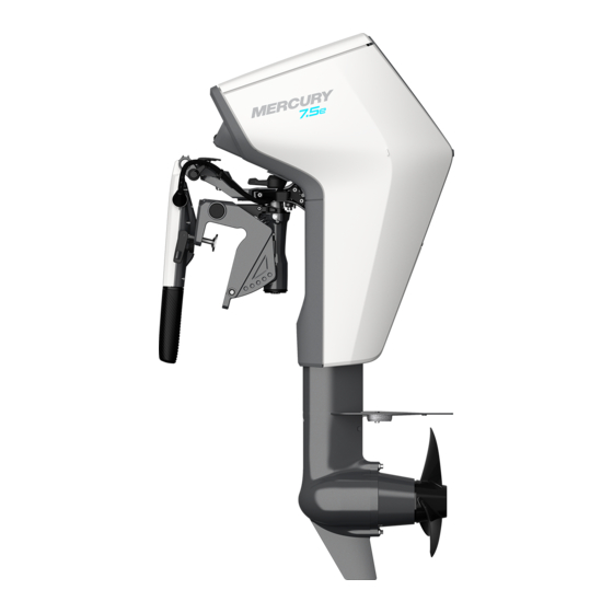
GENERAL INFORMATION Component Identification REMOTE CONTROL MODEL Hood Cowl Cavitation plate Anode Propeller Outboard Transom bracket assembly 75281 ... - Page 28 GENERAL INFORMATION TILLER MODEL 75458 Hood Cowl Cavitation plate Anode Propeller Outboard Transom bracket assembly Tiller handle Display ...
-
Page 29: Specifications
GENERAL INFORMATION Specifications Parameter Specification Outboard power rating 1 hp or 0.75 kW S (without battery) 20.0 kg (44.0 lb) L (without battery) 20.5 kg (45.2 lb) Weight XL (without battery) 21.0 kg (46.3 lb) Battery 7.3 kg (16 lb) Overall dimension Standard 38.1 cm (15 in.) - Page 30 GENERAL INFORMATION Notes: ...
-
Page 31: Battery
Keep the Mercury Avator outboard motor/battery away from children. • Protect the Mercury Avator battery against heat and fire. Do not store or operate the Mercury Avator battery in the presence of flammable vapors or flammable dust environments. Do not submerge the Mercury Avator battery in water. - Page 32 • The Mercury Avator battery contains hazardous materials which are stored safely inside. If the Mercury Avator battery is used incorrectly, toxic liquids may leak or gasses may release. Do not touch or ingest any of the released materials or inhale released fumes. Should inhalation, skin contact, eye contact or swallowing occur, take the necessary first aid measures immediately.
-
Page 33: Battery Disposal And Recycling Information
Battery Disposal and Recycling Information For battery disposal under warranty, a Mercury authorized dealer will process the disposal through Mercury's disposal process or be directed to dispose of it locally in accordance with regional regulations. For battery disposal outside of warranty use the following table for direction. -
Page 34: Battery Management System
BATTERY Battery Disposal and Recycling Information Area Contact Contiguous Mercury Marine technical service ‑ 920 929‑5000 or the United States local dealer to see if local services are available. and Canada Mercury Marine EMEA Dealer Locator:https://www.mercurymarine.com/en/europe/ find‑a‑dealer/ Mobile App Europe BRUNSWICK MARINE IN EMEA LLC Parc Industriel de Petit‑Rechain... -
Page 35: Battery Connector
BATTERY Battery Connector IMPORTANT: To prevent damage to the battery connectors of the outboard, use the weather cap to cover terminals when the battery is removed from the outboard. 76173 Battery Charger Selection The 7.5e Avator outboard comes with a 110‑watt battery charger. The 110‑watt charger has an estimated charge time of nine hours on a depleted 1 kWh battery. -
Page 36: Battery Charging Practices
4. Connect the output cable of the battery charger to the Avator battery. 5. Connect the AC power plug of the charger to the 100V~240V wall outlet. NOTE: Mercury Marine does not recommend leaving the battery on the charger unattended. If the battery is left on the charger beyond the fully charged state, the battery may be slightly below a full charge when the operator is ready to remove it from the charger. -
Page 37: Battery State Of Charge (Soc) Status
If temperatures are exceeded for the times shown, battery capacity will be reduced. Battery damage from improper storage is not covered under the Mercury Marine Limited Warranty for the battery. Battery State of Charge (SOC) Status 75311 <15% (blinking LED) -
Page 38: Battery Charging Status
BATTERY Battery Charging Status While the battery is charging, the LEDs are always illuminated. The LEDs will power off after charging has completed. The charger will power off after a short length of time due to regulations. 75323 <25% (blinking LED) 75321 25% ≤... -
Page 39: Battery Faults
Move the battery to a‑15‑45 °C (5‑113 °F) temperature location. 75329 Blinking LED Overcurrent/short‑circuit Make sure the battery is connected to a Mercury approved charging device. 75330 Blinking LED Permanent error Contact an authorized dealer for service. Do not attempt to use or charge the battery. - Page 40 BATTERY NOTICE Battery damage can be caused by incorrectly installing the battery or connecting the battery wiring incorrectly. Do not step, lean on, or place any objects on the battery. Always install the battery with the handle and LED indicators facing upward. 1.
- Page 41 BATTERY 4. Verify the battery is secure in the outboard. NOTE: The battery will lock into place when it is seated in the outboard. 74951 5. Close the hood on the outboard. NOTE: The hood will lock when it is closed. 74952 ...
-
Page 42: Battery Removal
BATTERY NOTE: The outboard is ready to be powered on. 74953 Battery Removal IMPORTANT: Removing the battery from the battery compartment removes power from the outboard. Do not remove the battery from the outboard with the outboard turned on, or when the boat is underway. 1. - Page 43 BATTERY 2. Slide the lock to unlock the battery. 74951 3. Pull the battery out of the outboard along the guide rails. 4. Install the connector cover on the battery connector inside the hood. 74950 5. Close the hood on the outboard. ...
- Page 44 BATTERY NOTE: The hood will lock when it is closed. 74952 ...
-
Page 45: Installation
Genuine Avator Accessories have been specifically designed and tested for Mercury Avator outboards. These accessories are available from Mercury Marine dealers, distributors and may be available directly from Mercury Marine. Make sure to download the Avator app to an Apple or Android device for specials, discounts, and rebates regarding all Avator accessories. -
Page 46: Installing The Outboard
MERCURY MARINE VALIDATED MOTOR MOUNTING HARDWARE IMPORTANT: Mercury Marine provides validated fasteners and installation instructions, including torque specifications, with all of Mercury outboards so they can be properly secured to boat transoms. Improper installation of the outboard can cause performance and reliability issues that can lead to safety concerns. - Page 47 INSTALLATION Minimum Transom Opening Single outboard (remote control models) 48.3 cm (19 in.) Single outboard (tiller handle models) 76.2 cm (30 in.) Transom thickness range Minimum 4.45 cm (1.75 in.) Maximum 6.35 cm (2.5 in.) INSTALLING THE OUTBOARD ON THE BOAT TRANSOM (TILLER AND REMOTE CONTROL MODELS) WARNING Failure to correctly fasten the outboard could result in the outboard propelling...
- Page 48 IMPORTANT: Do not use the transom assembly of the outboard to guide the drill. Use the included template to mark the holes and if a drill fixture is required, use the drill fixture specific to Avator 7.5e. 1. Place the template or drill fixture on the boat's transom, paying special attention to the centerline guide and the folded top of the template.
- Page 49 INSTALLATION 3. Use a 9 mm (3/8 in.) drill bit to drill the two lower holes through the transom. 75508 IMPORTANT: Do not apply marine sealer to the threads of the bolts. 4. Apply marine sealer (obtain locally) to the shanks of the bolts. 5.
- Page 50 INSTALLATION Description lb‑in. lb‑ft Fasteners 13.6 75335 10. Verify that the outboard anti‑ventilation plate is in‑line or within 25 mm (1 in.) of the bottom of the boat. Anti‑ventilation plate In‑line or within 25 mm (1 in.) 75513 QUICK-DISCONNECT DISABLE SCREW – TILLER MODELS ONLY This is a method to disable the quick‑disconnect mechanism from operating.
- Page 51 INSTALLATION 3. Hand tighten the torx screw. 76172 4. Verify the quick‑disconnect is disabled by pulling the slide and attempting to lift the outboard. 75507 LIFTING THE OUTBOARD IMPORTANT: Never lift the outboard from the battery handle while the battery is installed in the outboard. Injury or product damage/loss could result. 1.
-
Page 52: Quick Release - Tiller Models Only
INSTALLATION 2. Lift the outboard using the tiller handle, the hand hold on the upper portion of the rear cowling, just under the tiller arm assembly, or on the lower portion of the outboard at the drive extension housing. Use at least two different positions to grip the outboard depending on the operator's position inside or outside of the boat. -
Page 53: Remote Control Steering Cable Connections
INSTALLATION 2. Pull the slide until the slide stops moving. NOTE: Once the slide has cleared the probe assembly the outboard will be lifted up by the quick release spring. Or, if not installed yet, the transom bracket will be moved down and can be removed from the outboard for mounting. - Page 54 INSTALLATION Description lb‑in. lb‑ft Steering cable nut 47.5 – 75661 Steering bracket screw and washer (2) Steering cable seal Steering cable nut STEERING LINK ROD INSTALLATION WARNING Improper fasteners or improper installation procedures can result in loosening or disengagement of the steering link rod. This can cause a sudden, unexpected loss of boat control, resulting in serious injury or death due to occupants being thrown within or out of the boat.
- Page 55 INSTALLATION 1. Install the steering link rod onto the steering bracket threaded hole with the link rod screw, two washers, spacer, and a locknut. Do not tighten the link rod screw or the locknut. 75676 Screw Steering link rod 2. Install the loose end of the steering link onto the steering cable and secure with a washer and locknut.
-
Page 56: Cowl Replacement
Always put down tools and metal objects, and remove any metal jewelry or wristwatches before removing cowls. Electrical wiring connections should not be removed except by an Authorized Mercury Marine Dealer. The cowl panels must be removed in the following sequence: (The port and rear cowl panels may not need to be removed for some procedures). - Page 57 INSTALLATION 5. Rear cowl upper panel The cowl panels must be installed in the following sequence: (The port and rear cowl panels may not need to be installed for some procedures). 1. Rear cowl upper panel 2. Port cowl panel 3.
- Page 58 INSTALLATION 4. Tiller models only: disconnect the connector from the front cowl upper panel. 76044 FRONT COWL LOWER PANEL REMOVAL 1. Remove the four short hex head screws and the front cowl lower panel from the outboard. Short hex head screws (4) Front cowl lower panel a a a a 76045...
- Page 59 INSTALLATION STARBOARD COWL PANEL REMOVAL 1. Remove the screw from the starboard cowl panel. 76046 2. Remove the top short torx screw and the bottom torx long screw from the starboard cowl panel. Top screw Bottom torx long screw 76047 ...
- Page 60 INSTALLATION 3. Remove the five hex head screws and the starboard cowl panel from the outboard. Starboard cowl panel Hex head screws (5) 76051 STARBOARD COWL PANEL INSTALLATION 1. Align the starboard cowl panel pin with the outboard pin hole. 76067 2.
- Page 61 INSTALLATION IMPORTANT: Make sure that any wiring harnesses are not pinched between the screws and the outboard. Starboard cowl panel Hex head screws (5) 76051 3. Tighten the screws to the specified torque. Description lb‑in. lb‑ft Screws – 4. Secure the starboard cowl panel on the outboard with the top short torx and the bottom long torx screw.
- Page 62 INSTALLATION Description lb‑in. lb‑ft Top short torx screw and the – bottom long torx screw 6. Secure the starboard cowl panel to the outboard with the screw. 76046 7. Tighten the screw to the specified torque. Description lb‑in. lb‑ft Screw –...
- Page 63 INSTALLATION FRONT COWL LOWER PANEL INSTALLATION 1. Align the front cowl lower panel pins with the pin holes on the outboard. 76063 2. Install the front lower cowl on the outboard with the four short hex head screws. Short hex head screws (4) Front cowl upper panel a a a a 76045...
- Page 64 INSTALLATION FRONT COWL UPPER PANEL INSTALLATION 1. Tiller models only: connect the connector from the front cowl upper panel. 76044 2. Align the front cowl upper panel pins to the outboard. 76068 Tiller model shown, other models similar. ...
-
Page 65: Remote Wiring Harness Installation
INSTALLATION 3. Install the front cowling upper panel on the outboard with the four short hex head screws. Tiller model shown, other models similar. Short hex head screws (4) Front cowl upper panel 76043 4. Install the battery. Refer to Battery Installation. Remote Wiring Harness Installation 1. - Page 66 INSTALLATION 7. Secure the 14‑pin data harness to the outboard just behind the connector with a cable tie. 76098 8. Verify the connectors are connected by pulling on the connections. NOTE: The connectors should be aligned and seated flush for a proper connection.
- Page 67 7.62 cm (3 in.) of loose harness to provide strain relief to the component connection points. IMPORTANT: Failure to provide proper strain relief will eventually result in harness damage that will not be covered by the Mercury Limited Warranty provision. 18. Connect the 14‑pin data harness to the helm harness.
-
Page 68: Remote Control Diagram
INSTALLATION Remote Control Diagram 76102 Outboard motor 14‑pin harness Helm harness Power relay CAN terminators Remote display Lanyard stop switch Horn Avator ERC Steering wheel Steering cables 5‑way J‑box NMEA 2000 backbone with termination Transducer Components contained under cowl SmartCraft connect NMEA 2000 tee with fuse ... -
Page 69: Transporting
TRANSPORTING Aquatic Invasive Species (AIS) STOP AQUATIC HITCHHIKERS!™ Be A Good Steward. Clean. Drain. Dry. For additional information, visit StopAquaticHitchhikers.org. 68805 AIS and their spread can detrimentally impact the boating experience and the future of the boating lifestyle. Reducing the spread of AIS has led to significant national efforts to inspect boats moving between water bodies or across state and federal boundaries and could lead to delayed or denied access if AIS are suspected or found on board. - Page 70 TRANSPORTING 4. Use the quick release to separate the outboard from the transom bracket. Refer to Using the Quick Release ‑ Tiller Models Only. 5. Fold the tiller handle to the lowest position. 6. Position the tiller lock lever to the secure locking position. 7.
-
Page 71: Carrying Bag (Optional Accessory)
TRANSPORTING Carrying Bag (Optional Accessory) 75737 Trailering for Transportation TRAILERING FOR TRANSPORTATION - TILLER AND REMOTE CONTROL MODELS IMPORTANT: Remote control models must be trailered using the support brace included with the outboard. Tiller models ‑ Either remove the outboard from the boat, or use an outboard support brace. - Page 72 TRANSPORTING 4. Take a hold of the top cowl grip, and raise the outboard to an elevated trim position high enough to prevent contact with obstacles. 5. Insert and adjust the trailering support rod between the nose cone of the torpedo and the transom assembly.
-
Page 73: Features And Controls
FEATURES AND CONTROLS Tiller Handle Features IMPORTANT: Until the operator is familiar with the characteristics and features of this tiller handle control, it is strongly suggested to initially test‑operate the boat in a safe area. Use all ranges and features of the tiller handle control in an area free of swimmers, obstructions and in water deep enough to prevent beaching. - Page 74 FEATURES AND CONTROLS 76103 Tiller handle lock release lever Throttle grip friction knob Tiller handle • Tiller handle yaw ‑ The tiller handle yaw allows the operator to change the angle of the handle 12° left or right of center. For storage the tiller handle can be moved up to 90°...
- Page 75 FEATURES AND CONTROLS d. Release the yaw release and verify the lever is locked into position. 75531 Tiller handle yaw Tiller handle Tiller handle yaw release lever • Lanyard stop switch ‑ Refer to Lanyard Stop Switch. A spare lanyard stop switch clip is stored on the underside of the battery compartment hood.
-
Page 76: Copilot (Steering Friction Adjustment)
FEATURES AND CONTROLS • Throttle grip ‑ Controls the outboard speed and direction of travel. Align the throttle grip with the neutral detent on the tiller handle when starting or before engaging into the forward or reverse positions. Twist the throttle grip to increase the outboard speed. -
Page 77: Remote Control Features
FEATURES AND CONTROLS To increase friction, turn the copilot lever to the right, to decrease friction turn the copilot lever to the left. Copilot lever Left Right 76165 Remote Control Features IMPORTANT: Until the operator is familiar with these remote controls, it is strongly suggested to initially test‑operate the boat in a safe area. -
Page 78: Helm Mounted Lanyard Stop Switch
FEATURES AND CONTROLS IMPORTANT: Forcing the shift mechanism without squeezing the neutral lock bar can damage the remote control. 75535 Throttle/shift lever Neutral lock bar Ignition key switch—OFF, ON Helm Mounted Lanyard Stop Switch The helm‑mounted lanyard stop switch shuts the outboard off when the operator moves away from the boat controls. -
Page 79: Avator Outboard Trim System
FEATURES AND CONTROLS Avator Outboard Trim System WARNING Operating the outboard without ensuring the trim lock is engaged in a locked position can cause serious injury or death. The outboard can tilt upwards when decelerating or operating in reverse, causing loss of boat control. Always engage the trim lock of the outboard in the locked position before operating. - Page 80 FEATURES AND CONTROLS 2. Push down on the tiller handle with the handle locked in the raised position. 3. Grip the cowl hand hold and raise the outboard as far as it can travel. NOTE: The outboard will be at or near the horizontal position at the uppermost travel limit.
- Page 81 FEATURES AND CONTROLS IMPORTANT: Before trimming the outboard into the shallow water drive position, power off the outboard. While in the shallow water drive position, do not operate the outboard in reverse. Operate the outboard at slow speed, and keep the propeller submerged.
- Page 82 FEATURES AND CONTROLS Arrange passengers and the load in the boat so the weight is distributed evenly. 75542 Too much vertical operating angle (bow up) ‑ adjust in Not enough vertical operating angle (bow down) ‑ adjust out Vertical operating angle adjusted properly (bow slightly up) NOTE: When docking or using reverse, the outboard should be in the trim locked position during operation.
-
Page 83: Warning Horn
FEATURES AND CONTROLS • Increase clearance over submerged objects or a shallow bottom. • Increase steering pull to the left at a normal installation height. • In excess, cause boat porpoising (bouncing) or propeller ventilation. • Reduce visibility of objects in front of the boat. Warning Horn Remote control models will have the warning horn located under the helm. -
Page 84: Display Icon Legend
FEATURES AND CONTROLS CRITICAL If a critical state is detected, the audio warning system will sound for six seconds and then turn off. Horn (on or off) Time (in seconds) 53403 NONCONFIGURED ALARM If the helm has not been properly configured using the CDS G3 service tool, the audio warning system will sound for five one‑second intervals. - Page 85 FEATURES AND CONTROLS Icon Description Speed 76108 Power (kW) 76109 Distance remaining 76110 Settings 76111 Brightness 76112 Depth 76113 Throttle direction 76114 ALARM/WARNING Icon Description Active fault 76115 GPS fault 76116 ...
- Page 86 FEATURES AND CONTROLS Icon Description Attach lanyard 76117 Temperature fault 76118 Propulsion fault 76119 Battery fault 76120 Charge icon 76121 CHARGE Charge text 76122 Low battery icon 76123 LOW BATTERY Low battery text 76124 Left alarm chevron 76125 Right alarm chevron 76126 ...
- Page 87 FEATURES AND CONTROLS ACTIVE FEATURE Icon Description TROLL Troll active 76127 POSITIVE STATES Icon Description Charge icon 76128 SAVED Settings Saved text 76129 READY Ready state (neutral) 76130 UNITS/NUMBERS/LABELS Icon Description ALARM Alarm text 76131 TYPE Type in alarm type 76137 CODE Code in alarm code...
-
Page 88: Smartcraft Connect Installation
FEATURES AND CONTROLS Icon Description Estimated text (estimated time to charge, ESTIMATED estimated range) 76140 RANGE Range text (distance to discharged) 76141 km/h Kilometers per hour 76143 Miles per hour 76144 % (percent) 76146 Kilowatts of power 76147 Knots 76148 BATTERY INDICATION Icon Description... - Page 89 FEATURES AND CONTROLS SmartCraft CONNECT Serial Number Refer to SmartCraft CONNECT quick reference guide for the link to configuration instructions online. 1. Remove the battery from the outboard. Refer to Battery Removal. 2. Remove the front cowl upper panel from the outboard. Refer to Front Cowl Upper Panel Removal.
-
Page 90: Near Field Chipset (Nfc) Decal And Mercury Marine App
13. Install the battery in the outboard. Refer to Battery Installation. Near Field Chipset (NFC) Decal and Mercury Marine App The under‑hood label on the Avator 7.5e outboard contains an NFC that can be read by NFC‑enabled smart devices. •... - Page 91 FEATURES AND CONTROLS The Mercury Marine App provides useful information such as links to the Operations Manual, Quick Reference Guides, helpful tutorials, and mapping functionality. The Mercury Marine App will also provide data from the outboard/ battery if the optional accessory SmartCraft CONNECT is purchased and installed.
- Page 92 FEATURES AND CONTROLS Notes: ...
-
Page 93: Operation
OPERATION Prestarting Check List • The operator knows safe navigation, boating, and operating procedures. • An approved personal flotation device of suitable size is available for each person aboard. • A ring type life buoy or buoyant cushion designed to be thrown to a person in the water. -
Page 94: Powering On/Off The Outboard: Tiller Models
OPERATION Powering On/Off the Outboard: Tiller Models IMPORTANT: To stop the outboard in an emergency, pull the lanyard on the tiller handle. 1. Inspect the outboard and check the following items: • The battery is installed in the outboard. • The lanyard stop switch is attached. •... -
Page 95: Powering On/Off The Outboard: Remote Control Models
OPERATION NOTE: The display will show the current battery percent. READY 74745 3. To power off the outboard, press and hold the power button until the battery percent disappears. 74744 Powering On/Off the Outboard: Remote Control Models Inspect the outboard and check the following items: 1. - Page 96 OPERATION 3. The remote control is in the neutral position. 74907 4. The propeller is in the water and clear of any obstructions. POWER ON Turn the key to the ON position. 74947 ...
-
Page 97: Operating The Outboard - Remote Control Models
OPERATION NOTE: If the system has a remote display, the key switch will turn the display 74948 POWER OFF Turn the key to the OFF position. 74946 Operating the outboard ‑ Remote Control Models Before starting, read the Prestarting Check List and Prestarting Instructions in this section. - Page 98 OPERATION 1. Set the lanyard stop switch to the RUN position. Refer to Lanyard Stop Switch. Attach the lanyard to the operator. 19791 2. Verify the remote control handle is in the neutral position. 75267 ...
-
Page 99: Operating The Outboard - Tiller Handle Models
OPERATION 3. Turn te key to the ON position. 74947 Key in ON position 4. Check the display that there are no active faults or conditions that may cause active faults. 5. Check the safety and positioning of passengers before operating the outboard. -
Page 100: Outboard Settings - Tiller Models
OPERATION 5. Check the display for the E‑stop fault due to lanyard activation has cleared and there are no active faults or conditions that may cause active faults. 6. Check the safety and positioning of passengers before operating the outboard. 7. - Page 101 OPERATION NOTE: The current throttle direction set point will flash. 74750 2. Use the left or right arrow to select the forward direction of the tiller handle. 74753 Left arrow Right arrow ...
- Page 102 OPERATION 3. Press the menu button to save the setting. SAVED 74754 NOTE: The current unit of measure set point will flash. 74755 ...
- Page 103 OPERATION 4. Use the left or right arrow to select the type of units to be displayed. Left arrow Right arrow km/h 74756 5. Press the menu button to save the setting. km/h SAVED 74757 NOTE: Setup is complete. The display will revert back to the main screen. ...
-
Page 104: Outboard Settings - Remote Control Models
OPERATION Outboard Settings ‑ Remote Control Models 1. Press and hold the menu button for two seconds. READY READY 76167 NOTE: The current unit of measure set point will flash. 2. Press the left or right arrow to select the type of units to be displayed. 76168 Current unit of measure Right arrow... -
Page 105: Using And Changing Directional Controls
OPERATION 3. Press the menu button to save the setting. km/h SA VED 76169 NOTE: Setup is complete. The display will revert back to the main screen. READY READY 76170 Using and Changing Directional Controls IMPORTANT: Observe the following: • Never change the directional control rapidly from reverse to forward without stopping at neutral to allow the propeller to stop spinning. - Page 106 OPERATION • Tiller handle models ‑ Three directional control positions provide boat operation: forward (F), neutral (N), and reverse (R). When changing directional control, always stop at the neutral position and allow the propeller to stop turning. NOTE: Throttle direction configuration is dependent on outboard setup. Refer to Outboard Settings ‑...
-
Page 107: Powering Down The Outboard
OPERATION • After placing the directional control into forward or reverse, move the remote control lever or rotate the throttle control grip to move the boat. Powering Down the Outboard REMOTE CONTROL MODELS 1. Move the remote control to the neutral position and confirm that the boat has reduced speed. -
Page 108: Recommended Operating Temperature Ranges For The Avator 7.5E Outboard
Recommended Operating Temperature Ranges for the Avator 7.5e Outboard The Avator 7.5e outboard and battery were designed to operate in ambient air temperature ranges above 0 °C (32 °F) and below 45 °C (113 °F). Operating above the recommended ambient air temperature limit could cause the motor or battery to overheat. -
Page 109: Maintenance
To keep the outboard in the best operating condition, it is important that the outboard receive the periodic inspections and maintenance listed in the Inspection and Maintenance Schedule. Mercury Marine urges the operator to keep it maintained properly to ensure that the safety of the operator and the passengers, and retain its dependability. -
Page 110: Inspection And Maintenance Schedule
Wash off any salt buildup from the under cowl components with fresh water. After washing, allow the under cowl components to dry. Apply Quicksilver or Mercury Precision Lubricants Corrosion Guard spray on the external metal surfaces of the under cowl components. - Page 111 MAINTENANCE Daily Check Check the tightness of the transom clamp bolts (tiller models). Check the steering system for binding. Inspect the propellers for damage. Inspect the battery for damages and proper installation. Check the state of charge of the battery. 100 Hour Maintenance Dealer (100 Hours or Before Long‑Term Storage)
-
Page 112: Corrosion Control Anode
MAINTENANCE Dealer 3 Year or 300 Hour Maintenance Item Remote control models only ‑ inspect the helm and outboard wire harness connectors. IMPORTANT: Do not use any version or brand of contact cleaner on the helm or outboard wire harness. Contact cleaner is harmful to the seals of the connectors. -
Page 113: Propeller Replacement
MAINTENANCE Propeller Replacement PROPELLER REMOVAL WARNING Rotating propellers can cause serious injury or death. Never operate the boat out of the water with a propeller installed. Before installing or removing a propeller, place the outboard in neutral and activate the lanyard stop switch to prevent the outboard from starting. - Page 114 MAINTENANCE PROPELLER INSTALLATION WARNING Rotating propellers can cause serious injury or death. Never operate the boat out of the water with a propeller installed. Before installing or removing a propeller, place the outboard in neutral and activate the lanyard stop switch to prevent the outboard from starting.
- Page 115 MAINTENANCE Description lb‑in. lb‑ft Propeller nut 75.2 – 75728 Propeller nut Propeller Shaft Propeller sheer pin ...
- Page 116 MAINTENANCE Notes: ...
-
Page 117: Storage Preparation
30 days, this is detrimental to the battery and is considered abusive. The battery monitoring system (BMS) monitors storage and charging practices. Mercury Marine requests this data when a battery is submitted for a warranty claim. Abusive storage practices can cause the battery warranty claim to be rejected. -
Page 118: Protecting External Outboard Components
• Touch‑up any paint nicks. See the local dealer for touch‑up paint. • Spray Quicksilver or Mercury Precision Lubricants Corrosion Guard on external metal surfaces (except corrosion control anodes). IMPORTANT: Do not apply corrosion guard to the exposed terminals of the battery connection. -
Page 119: Troubleshooting
TROUBLESHOOTING Fuse Replacement LOCATION OF FUSES The outboard 12‑volt 5‑amp fuse is located under the hood. 75729 Fuse location FUSE IDENTIFICATION AND REPLACEMENT IMPORTANT: Always carry spare 5‑amp 12‑volt fuses. Do not attempt to service the 48‑volt circuit fuse. If suspected to be failed, the outboard needs to be serviced by an authorized technician. -
Page 120: Outboard Will Not Power Up
TROUBLESHOOTING Outboard Will Not Power Up NOTE: If the outboard has discharged the battery to a very low state, the battery will need to be charged as soon as possible to prevent permanent battery damage and negative affects to the warranty of the battery. If a fault is present upon powering on the outboard, do not use the outboard. -
Page 121: Battery Will Not Hold Charge
Battery Will Not Charge with Charger Possible Causes Recommended Maintenance IMPORTANT: Do not use any charger except Charger not compatible Mercury Avator specific chargers. Aftermarket with Avator outboard. chargers may damage the battery. Poor connection between Ensure full engagement of the connectors the charger and the between the battery and charger. - Page 122 TROUBLESHOOTING Possible Causes Recommended Maintenance Battery temperature is Disconnect the charger and allow the battery to elevated. cool before reconnecting. Use the LEDs on the charger and battery to Battery is faulted. determine faults, charge status, and charger function. ...
-
Page 123: Operator Service Assistance
OPERATOR SERVICE ASSISTANCE Service Assistance LOCAL REPAIR SERVICE If service is needed for the Mercury outboard powered boat, take it to an authorized dealer. Only authorized dealers specialize in Mercury products and have factory‑trained mechanics, special tools and equipment, and genuine Mercury Avator parts and accessories to properly service the outboard. - Page 124 RESOLVING A PROBLEM Satisfaction with the Mercury product is important to the dealer and to Mercury Marine. If there is ever a problem, question or concern about the power package, contact the dealer or any authorized Mercury dealership. If additional assistance is needed: 1.
-
Page 125: Ordering Literature
Before ordering literature, have the following information about the power package available: Outboard Serial Model Number KiloWattHour rating or HP output UNITED STATES AND CANADA For additional literature for the Mercury Marine power package, contact the nearest Mercury Marine dealer or contact: ... - Page 126 (920) 929‑4894 P.O. Box 1939 Fond du Lac, WI 54936-1939 OUTSIDE THE UNITED STATES AND CANADA Contact the nearest Mercury Marine authorized service center to order additional literature that is available for the particular power package. Mercury Marine Submit the following...
-
Page 127: Maintenance Log
MAINTENANCE LOG Maintenance Log Record all maintenance performed on the outboard here. Be sure to save all work orders and receipts. Date Maintenance Performed Outboard Hours ... - Page 128 MAINTENANCE LOG Notes: ...
-
Page 129: Predelivery Inspection (Pdi)
PREDELIVERY INSPECTION (PDI) Predelivery Inspection (PDI) OUTBOARD INFORMATION Outboard Information Outboard kilowatt rating/Mercury Avator power rating Outboard serial number Battery serial number(s) Propeller size Boat brand Boat model Boat length TECHNICIAN INFORMATION I certify that the following checks and inspections have been completed. - Page 130 PREDELIVERY INSPECTION (PDI) Battery software version SmartCraft CONNECT (if installed) software version Can tiller throttle directional operation be changed from display? Battery state of charge (SOC) levels report correctly and accurately on display? Verified all audible and displayed warning systems operation? OUTBOARD STEERING Tiller models: Does tiller throttle function? Tiller models: Is tiller lanyard included and does tiller lanyard function?
- Page 131 PREDELIVERY INSPECTION (PDI) BATTERIES How many batteries are being sold with this outboard? Provide kWh of each battery Are switch box connections tight? Has correct cable stacking been followed with protective covering installed? GENERAL HARNESS ROUTING Proper switch box orientation and mounted in a suitable location? Proper data harness and power supply wiring retention and strain relief? Proper wiring service/drip loop to prevent water intrusion? If equipped are remote control and electric helm connected and proper...
- Page 132 Check battery levels post water test. Submit full report with PDI. Completion date. Clear all Freeze Frames and save a full report. Completed? Submit a full report with faults and history cleared to Mercury Technical Service and list email address. CUSTOMER DELIVERY Daily inspections/maintenance/documentation? Explained and demonstrated procedure to check battery levels.
- Page 133 PREDELIVERY INSPECTION (PDI) Boat speed and source (GPS in display). Electric steering operational and handling characteristics acceptable? Explain and review the remote control features and operation (if equipped)? BOAT Reviewed all boat electrical systems (lights, breakers, pumps) with consumer? Has the customer approved the external appearance and condition of product? SAFETY Operation of all safety equipment‑...
Need help?
Do you have a question about the Avator 7.5e and is the answer not in the manual?
Questions and answers
What is the diameter of the shaft that rest s or drops into the quick connect assembly?