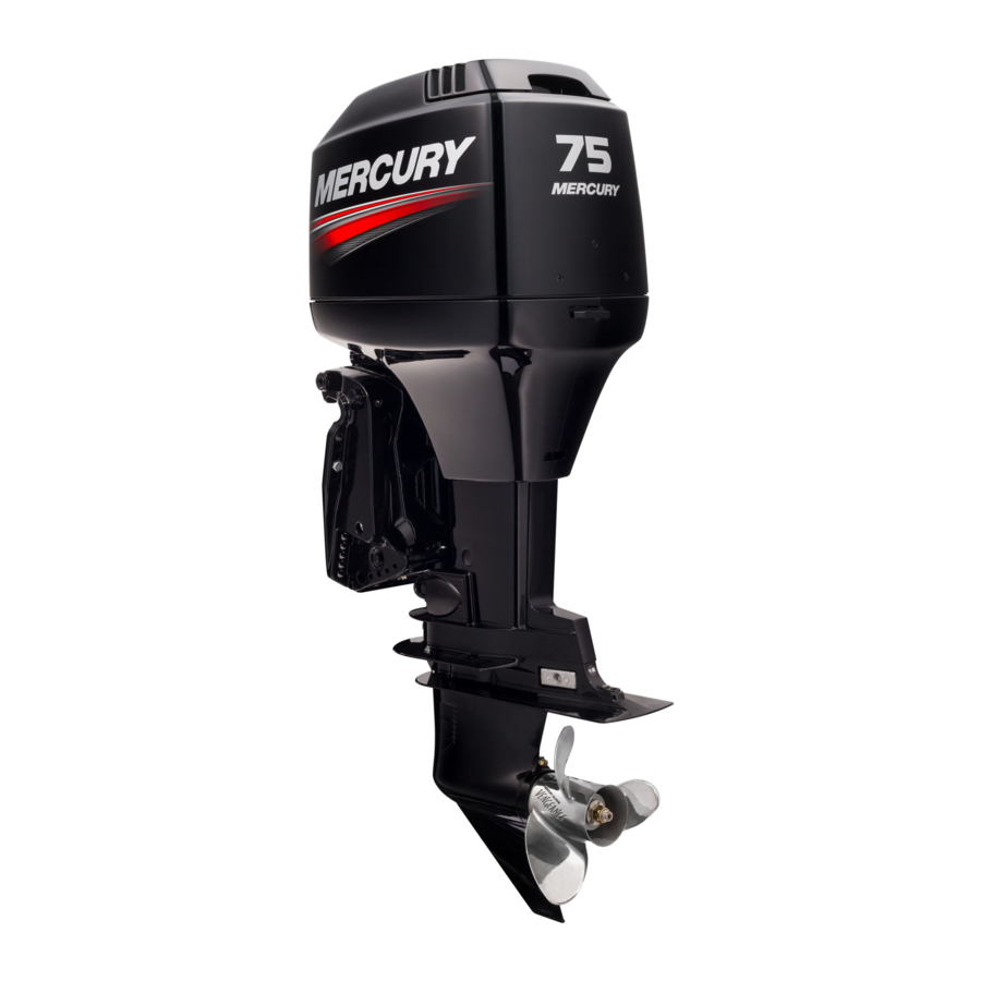
Mercury 75 Operation Maintenance Warranty Installation Manual

Mercury 75 Operation Maintenance Warranty Installation Manual

Hide thumbs Also See for 75:
Table of Contents

Advertisement

Outboard
Operation
Maintenance
Warranty
Installation
Manual

Advertisement

Table of Contents
loading

Summary of Contents for Mercury 75

  • Page 1 Outboard Operation Maintenance Warranty Installation Manual...
  • Page 3 Declaration of Conformity – For Recreational Craft Propulsion Engines with the Requirements of Directive 94/25/EC as amended by Directive 2003/44/EC Name of engine manufacturer: Mercury Marine Address: W6250 W. Pioneer Road, P.O. Box 1939 Town: Fond du Lac, WI Post Code: 54936‑1939 Country: USA Name of Authorized Representative: Brunswick Marine in EMEA Inc.
  • Page 4 Module H Name of engine family number(s) or engine Certificate family code(s): starting serial number 1.5L OptiMax 75, 90, 115, 115 0B228000 RCD‑H‑2 Rev 4 Pro XS, 125 hp, 80 Jet 2.5L OptiMax 135, 150, 150 0B228000 RCD‑H‑2 Rev 4 Pro XS, 175 hp 3.0L OptiMax 200, 200 Pro XS,...
  • Page 5 Mercury Marine EPA Emissions Regulations Outboards sold by Mercury Marine in the United States are certified to the United States Environmental Protection Agency as conforming to the requirements of the regulations for the control of air pollution from new outboard motors.
  • Page 6 Please review this information. The description and specifications contained herein were in effect at the time this manual was approved for printing. Mercury Marine, whose policy is one of continued improvement, reserves the right to discontinue models at any time, and to change specifications, designs, methods, or procedures without notice and without incurring obligation.
  • Page 7: Table Of Contents

    WARRANTY INFORMATION Warranty Registration United States and Canada..........1 Transfer of Warranty United States and Canada..........1 Transfer of Mercury Product Protection (Extended Service Coverage) Plan United States and Canada.................. 2 Mercury Jet Products Limited Warranty.............. 2 3 Year Limited Warranty Against Corrosion............5 Warranty Coverage and Exclusions..............
  • Page 8 Avoiding Fuel Flow Restriction................. 45 Low Permeation Fuel Hose Requirement ............45 EPA Pressurized Portable Fuel Tank Requirements........46 Fuel Demand Valve (FDV) Requirement............46 Mercury Marine's Pressurized Portable Fuel Tank........... 46 Oil Recommendation..................47 Filling Oil Injection System................48 Filling Fuel Tank....................50 Features and Controls Remote Control Features.................
  • Page 9 Maintenance Outboard Care....................73 EPA Emissions Regulations................73 Inspection and Maintenance Schedule............. 74 Flushing the Cooling System ................77 Top Cowl Removal and Installation..............77 Cleaning Care for Top Cowl................78 Flywheel Cover Removal and Installation............78 Side Panel Removal and Installation..............79 OIl Injection System..................
  • Page 10 Performance Loss................... 112 Battery Will Not Hold Charge................112 Jet Application Troubleshooting..............112 Outboard Installation Mercury Marine Validated Engine Mounting Hardware........114 Accessories Mounted to the Transom Clamp Bracket........114 Important Information..................118 Boat Horsepower Capacity................118 Start in Gear Protection.................. 119 Fuel System....................
  • Page 11: Warranty Information

    Federal Safety Act be required. You may change your registered address at any time, including at time of warranty claim, by calling Mercury Marine or sending a letter or fax with your name, old address, new address, and engine serial number to Mercury Marine’s warranty registration department.
  • Page 12: Transfer Of Mercury Product Protection (Extended Service Coverage) Plan United States And Canada

    UNITED STATES AND CANADA Outside the United States and Canada ‑ Check with your local distributor. WHAT IS COVERED Mercury Marine warrants its new Jet products to be free of defects in material and workmanship during the period described below.
  • Page 13 COVERAGE Warranty coverage is available only to retail customers that purchase from a dealer authorized by Mercury Marine to distribute the product in the country in which the sale occurred, and then only after the Mercury Marine specified predelivery inspection process is completed and documented. Warranty coverage becomes available upon proper registration of the product by the authorized dealer.
  • Page 14 If purchaser cannot deliver the product to such a dealer, written notice must be given to Mercury. We will then arrange for the inspection and any covered repair. Purchaser, in that case, shall pay for all related transportation charges and/or travel time.
  • Page 15: Year Limited Warranty Against Corrosion

    COVERAGE: Warranty coverage is available only to retail customers that purchase from a Dealer authorized by Mercury Marine to distribute the product in the country in which the sale occurred, and then only after the Mercury Marine specified predelivery inspection process is completed and documented.
  • Page 16 Purchaser shall not, unless requested by Mercury, ship the product or parts of the product directly to Mercury. Proof of registered ownership must be presented to the dealer at the time warranty service is requested in order to obtain coverage.
  • Page 17: Warranty Coverage And Exclusions

    WARRANTY INFORMATION For additional information regarding events and circumstances covered by this warranty, and those that are not, see the Warranty Coverage section of the Operation and Maintenance Manual, incorporated by reference into this warranty. DISCLAIMERS AND LIMITATIONS: THE IMPLIED WARRANTIES OF MERCHANTABILITY AND FITNESS FOR A PARTICULAR PURPOSE ARE EXPRESSLY DISCLAIMED.
  • Page 18 8. Use of other than Mercury Precision or Quicksilver parts when making warranty repairs. 9. Oils, lubricants, or fluids changed as a matter of normal maintenance is customer's responsibility unless loss or contamination of same is caused by product failure that would be eligible for warranty consideration.
  • Page 19: U.s. Epa Emissions Limited Warranty

    U.S. EPA Emissions Limited Warranty Consistent with the obligations created by 40 CFR Part 1045, Subpart B, Mercury Marine provides a five year or 175 hours of engine use warranty, whichever occurs first, to the retail customer, that the engine is designed, built,...
  • Page 20: California Emissions Limited Warranty

    Mercury Marine for certification from the California Air Resources Board, for the period of time, and under the conditions, identified below. The cost to diagnose a warranty failure is covered under the warranty (if the warranty claim is approved).
  • Page 21 Mercury with a reasonable opportunity to repair and reasonable access to the product for warranty service. Warranty claims shall be made by delivering the product for inspection to a Mercury dealer authorized to service the product. If purchaser cannot deliver the product to such a dealer, please notify Mercury Marine and Mercury will then arrange for the inspection and any covered repair.
  • Page 22: California Air Resources Board Explanation Of Your California Emission Control Warranty Statement

    Also included may be hoses, belts, connectors, and other emission‑related assemblies. Where a warrantable condition exists, Mercury Marine will repair your outboard engine at no cost to you, including diagnosis, parts, and labor.
  • Page 23: Emission Certification Star Label

    WARRANTY INFORMATION As the outboard engine owner, you should, however, be aware that Mercury Marine may deny you warranty coverage if your outboard engine or a part has failed due to abuse, neglect, improper maintenance, or unapproved modifications. You are responsible for presenting your outboard to a Mercury dealer authorized to service the product as soon as a problem exists.
  • Page 24: Warranty Policy-Australia And New Zealand

    What is Covered Mercury Marine warrants its new products to be free of defects in material and workmanship during the period described following. The benefits to the consumer given by the warranty are in addition to other rights and remedies of the consumer under a law in relation to the goods or services to which the warranty relates.
  • Page 25 The customer must provide Mercury Marine with a reasonable opportunity to repair and reasonable access to the product for warranty service. Warranty claims shall be made by delivering the product for inspection to a Mercury Marine dealer authorized to service the product. A list of dealers and their contact details is available at www.mercurymarine.com.au.
  • Page 26 Mercury Marine to make any affirmation, representation or warranty regarding the product, other than those contained in this limited warranty, and if made, shall not be enforceable against Mercury Marine. For additional information regarding events and circumstances covered by this...
  • Page 27 You may change your address at any time, including at the time of the warranty claim, by calling Mercury Marine or sending a letter or fax with your name, old address, new address, and hull identification number (HIN) to Mercury Marine’s...
  • Page 28: Global Warranty Charts Outboard And Jets

    FourStroke (2.5 ‑ 300 hp including Verado, Pro FourStroke and jet 3 years 3 years outboards) OptiMax (75 ‑ 250 hp including Pro 3 years 3 years XS and jet outboards ) OptiMax jet drive (200 and 250 hp) 1 year...
  • Page 29 WARRANTY INFORMATION Racing Product Standard Limited Standard Limited (Recreation use only) Warranty Corrosion Warranty OptiMax (250 XS) 2 years 3 years OptiMax (225 Sport XS) 2 years 3 years OptiMax (300 XS) 2 years 3 years Verado (350 SCi) 2 years 3 years Outside of Canada For product purchased outside of Canada, contact the distributor in your...
  • Page 30 WARRANTY INFORMATION ASIA WARRANTY CHARTS–OUTBOARD AND JET Standard Product Standard Limited Commercial (Recreational Limited Corrosion Application only) Warranty Warranty 2‑Stroke 1 year 3 years Contact the Marine FourStroke 1 year 3 years Power Service Center OptiMax 1 year 3 years closest to you Verado 1 year...
  • Page 31 WARRANTY INFORMATION Standard Racing Product Standard Limited Commercial (Recreational Limited Corrosion Application only) Warranty Warranty Contact the Marine Verado 350 SCi 2 years 3 years Power Service Center closest to you Outside Europe and CIS For products purchased outside of Europe and CIS regions, contact the distributor in your country, or the Marine Power Service Center closest to you.
  • Page 32 WARRANTY INFORMATION SOUTH AFRICA WARRANTY CHARTS–OUTBOARD AND JET Standard Product Standard Limited Commercial (Recreational Limited Corrosion Application only) Warranty Warranty 2‑Stroke 2 years 3 years FourStroke 2 years 3 years Contact the Marine OptiMax Power Service Center (including Pro 3 years 3 years closest to you Verado...
  • Page 33: General Information

    GENERAL INFORMATION Boater's Responsibilities The operator (driver) is responsible for the correct and safe operation of the boat and the safety of its occupants and general public. It is strongly recommended that each operator read and understand this entire manual before operating the outboard.
  • Page 34: High-Speed And High-Performance Boat Operation

    When choosing a propeller, a full selection of aluminum and stainless steel propellers specifically designed for your outboard are available through Mercury Marine. To view the entire product offering and find the correct propeller that is best suited for your application, visit www.mercmarinepropellers.com or see your local authorized Mercury dealer.
  • Page 35 GENERAL INFORMATION IMPORTANT: To ensure proper fit, and performance, Mercury Marine recommends the use of Mercury or Quicksilver branded propellers and mounting hardware. Propellers are designated by the diameter, pitch, number of blades, and material. The diameter and pitch are stamped (cast) into the side or the end of the propeller hub.
  • Page 36: Outboard Remote Control Models

    PROPELLER MATERIAL Most propellers manufactured by Mercury Marine are made from either aluminum or stainless steel. Aluminum is suitable for general purpose use and is standard equipment on many new boats. Stainless steel is over five times more durable than aluminum and typically provides performance gains in acceleration and top end speed due to design efficiencies.
  • Page 37: Remote Steering Notice

    GENERAL INFORMATION Remote Steering Notice The steering link rod that connects the steering cable to the engine must be fastened utilizing self‑locking nuts. These self‑locking nuts must never be replaced with common nuts (nonlocking) as they will work loose and vibrate off, freeing the link rod to disengage.
  • Page 38 GENERAL INFORMATION The lanyard cord is usually 122–152 cm (4–5 feet) in length when stretched out, with an element on one end made to be inserted into the switch and a clip on the other end for attaching to the operator's PFD or wrist. The lanyard is coiled to make its at‑rest condition as short as possible to minimize the likelihood of lanyard entanglement with nearby objects.
  • Page 39 GENERAL INFORMATION While activation of the lanyard stop switch will stop the engine immediately, a boat will continue to coast for some distance depending upon the velocity and degree of any turn at shut down. However, the boat will not complete a full circle.
  • Page 40: Protecting People In The Water

    GENERAL INFORMATION Protecting People in the Water WHILE YOU ARE CRUISING It is very difficult for a person standing or floating in the water to take quick action to avoid a boat heading in his/her direction, even at slow speed. 21604 Always slow down and exercise extreme caution any time you are boating in an area where there might be people in the water.
  • Page 41 GENERAL INFORMATION Persons on the front deck could easily be thrown overboard or persons dangling their feet over the front edge could get their legs caught by a wave and pulled into the water. 26782 WARNING Sitting or standing in an area of the boat not designed for passengers at speeds above idle can cause serious injury or death.
  • Page 42: Wave And Wake Jumping

    GENERAL INFORMATION Wave and Wake Jumping Operating recreational boats over waves and wake is a natural part of boating. However, when this activity is done with sufficient speed to force the boat hull partially or completely out of the water, certain hazards arise, particularly when the boat enters the water.
  • Page 43: Impact With Underwater Hazards

    GENERAL INFORMATION Impact with Underwater Hazards Reduce speed and proceed with caution whenever you drive a boat in shallow water areas, or in areas where you suspect underwater obstacles may exist which could be struck by the outboard or the boat bottom. The most important thing you can do to help reduce injury or impact damage from striking a floating or underwater object is to control the boat speed.
  • Page 44: Exhaust Emissions

    Operating a boat or engine with impact damage can result in product damage, serious injury, or death. If the vessel experiences any form of impact, have an authorized Mercury Marine dealer inspect and repair the vessel or power package. Exhaust Emissions...
  • Page 45 GENERAL INFORMATION GOOD VENTILATION Ventilate the passenger area, open side curtains or forward hatches to remove fumes. Example of desired air flow through the boat: 21622 POOR VENTILATION Under certain running and/or wind conditions, permanently enclosed or canvas enclosed cabins or cockpits with insufficient ventilation may draw in carbon monoxide.
  • Page 46: Selecting Accessories For Your Outboard

    Some accessories not manufactured or sold by Mercury Marine are not designed to be safely used with your outboard or outboard operating system. Read the installation, operation and maintenance manuals for all your selected accessories.
  • Page 47 (refer to your boat's capacity plate). Know your boat's operating and loading limitations. Know if your boat will float if it is full of water. When in doubt, contact your authorized Mercury Marine dealer or the boat manufacturer. Ensure that everyone in the boat is properly seated.
  • Page 48: Recording Serial Number

    GENERAL INFORMATION Be alert. • The operator of the boat is responsible by law to maintain a proper lookout by sight and hearing. The operator must have an unobstructed view particularly to the front. No passengers, load, or fishing seats should block the operator's view when the boat is above idle or planing transition speed.
  • Page 49: Specifications

    GENERAL INFORMATION Specifications 115/115 Pro Models Horsepower Kilowatts 55.2 66.2 84.6 91.3 Full throttle 5000–5750 RPM RPM range Idle speed in 625–675 RPM forward gear Number of cylinders Piston 1523.5 cc (92.9 in³) displacement Cylinder bore 92.11 mm (3.63 in.) Piston stroke 76.2 mm (3.0 in.) Recommended...
  • Page 50: 80 Jet Optimax Specifications

    *Battery manufacturers may rate and test their batteries to different standards. MCA, CCA, Ah, and reserve capacity (RC) are the ratings recognized by Mercury Marine. Manufacturers that use standards different than these, such as equivalent MCA, do not meet Mercury Marine battery requirements.
  • Page 51: Component Identification

    GENERAL INFORMATION Component Identification Top cowl Auxiliary tilt switch Transom brackets Gearcase Cooling water intake holes Trim tab Anti‑ventilation plate Driveshaft housing Water pump indicator hole Bottom cowl 29461...
  • Page 52: Component Identification

    GENERAL INFORMATION Component Identification Top cowl Auxiliary tilt switch Transom brackets Jet drive housing Water intake housing Reverse gate Water outlet nozzle Driveshaft housing Water pump indicator hole Bottom cowl 33496...
  • Page 53: Transporting

    TRANSPORTING Trailering Boat/Outboard Trailer your boat with the outboard tilted down in a vertical operating position. If additional ground clearance is required, the outboard should be tilted up using an accessory outboard support device. Refer to your local dealer for recommendations.
  • Page 54: Fuel And Oil

    FUEL RATINGS Mercury Marine engines will operate satisfactorily when using a major brand of unleaded gasoline meeting the following specifications: USA and Canada ‑ having a posted pump octane rating of 87 (R+M)/2 minimum.
  • Page 55: Fuel Requirements

    Fuel Additives To minimize carbon deposit buildup in the engine, it is recommended to add Mercury or Quicksilver Quickstor fuel stabilizer additive to the engine's fuel at each tank fill throughout the boating season. Use additive as directed on container.
  • Page 56: Epa Pressurized Portable Fuel Tank Requirements

    Vent/water drain holes 46273 Mercury Marine's Pressurized Portable Fuel Tank Mercury Marine has created a new portable pressurized fuel tank that meets the preceding EPA requirements. These fuel tanks are available as an accessory or are provided with certain portable outboard models.
  • Page 57: Oil Recommendation

    Outboard Oil Mercury OptiMax/DFI or Quicksilver DFI 2‑Cycle Engine Oil is recommended for your engine. If Mercury OptiMax/DFI or Quicksilver DFI 2‑Cycle Engine Oil is not available, we recommend using Mercury or Quicksilver TC‑W3 Premium Plus 2‑Cycle Oil. Severe engine damage may result from use of an inferior oil.
  • Page 58: Filling Oil Injection System

    FUEL AND OIL Mercury Racing 2‑Stroke Oil is recommended for OptiMax engines that are used in applications of extreme loads associated with commercial, work, or extended periods of high RPM. The added lubrication and protection properties with Mercury Racing 2‑Stroke oil, maximizes engine horsepower while protecting against heat, reduces wear and carbon deposit build‑up.
  • Page 59 FUEL AND OIL 5. Oil filler caps with a chain ‑ Check the oil level on the chain. The first ball marker indicates 0.94 liters (1 US qt) low. The second ball marker indicates 1.89 liters (2 US qt) low. 37146 Add 0.94 liters (1 US qt) Add 1.89 liters (2 US qt)
  • Page 60: Filling Fuel Tank

    FUEL AND OIL Filling Fuel Tank WARNING Avoid serious injury or death from a gasoline fire or explosion. Use caution when filling fuel tanks. Always stop the engine and do not smoke or allow open flames or sparks in the area while filling fuel tanks. Fill the fuel tanks outdoors away from heat, sparks, and open flames.
  • Page 61: Features And Controls

    FEATURES AND CONTROLS Remote Control Features Your boat may be equipped with one of the Mercury Precision or Quicksilver remote controls shown. If not, consult your dealer for a description of the functions and operations of the remote control. 26800 Control handle –...
  • Page 62 FEATURES AND CONTROLS 1. Continuous six second beep: Indicates a critical engine condition. Depending on the condition, the Engine Guardian system may engage and protect the engine by limiting power. You should return to port immediately and contact your servicing dealer. 2.
  • Page 63: Power Trim And Tilt

    2. Engage the throttle. If the engine does not respond, repeat step one. SMARTCRAFT PRODUCT A Mercury SmartCraft System instrument package can be purchased for this outboard. A few of the functions the instrument package will display are engine RPM, coolant temperature, battery voltage, fuel consumption, and engine operating hours.
  • Page 64 FEATURES AND CONTROLS POWER TRIM OPERATION NOTE: When traveling at slow speeds, a slight drop in engine RPM may be noticed on occasion when engaging power trim. This condition is normal and has no adverse affect on the outboard. With most boats, operating around the middle of the trim range will give satisfactory results.
  • Page 65 FEATURES AND CONTROLS • Lift the bow higher out of the water. • Generally increase top speed. • Increase clearance over submerged objects or a shallow bottom. • Increase steering torque or pull to the left at a normal installation height (with the normal right‑hand rotation propeller).
  • Page 66 FEATURES AND CONTROLS Turn out the manual tilt release valve three turns counterclockwise. This allows manual tilting of the outboard. Tilt the outboard to the desired position and tighten the manual tilt release valve. 22362 SHALLOW WATER OPERATION When operating your boat in shallow water, you can tilt the outboard beyond the maximum trim range to prevent hitting bottom.
  • Page 67: Trim Tab Adjustment

    FEATURES AND CONTROLS Trim Tab Adjustment Propeller steering torque will cause your boat to pull in one direction. This steering torque is a normal thing that results from your outboard not being trimmed so the propeller shaft is parallel to the water surface. The trim tab can help compensate for this steering torque in many cases and can be adjusted within limits to reduce any unequal steering effort.
  • Page 68: Operation

    OPERATION Important Information IMPORTANT DAILY INSPECTION BEFORE EACH USE Any outboard mounted on the boat must have the mounting hardware inspected and checked to ensure that the hardware has not become loose. A decal on the transom bracket reminds the owner to check the fasteners securing the outboard to the transom before each use.
  • Page 69: Prestarting Check List

    OPERATION Periodically consult with your dealer to get the latest gasoline and oil recommendations. If Mercury Precision or Quicksilver 2‑Cycle Outboard Oil is not available, substitute another brand of 2‑Cycle outboard oil that is NMMA Certified TC‑W3. The use of an inferior 2‑Cycle outboard oil can reduce engine durability.
  • Page 70: Operating At High Elevations

    Wash the outboard exterior and flush out the exhaust outlet of the propeller and gearcase with fresh water after each use. Each month, spray Mercury Precision or Quicksilver Corrosion Guard on external metal surfaces. Do not spray on corrosion control anodes as this will reduce the effectiveness of the anodes.
  • Page 71: Starting The Engine

    OPERATION Break‑in Procedure • Do not idle for more than five minutes. • Run the engine the majority of the time between 4000–5400 RPM (approximately three‑quarter throttle). • Short bursts of wide‑open throttle for 10 seconds or less are acceptable. •...
  • Page 72 OPERATION 3. Position the fuel line primer bulb so the arrow on the side of the bulb is pointing up. Squeeze the fuel line primer bulb several times until it feels firm. 27348 4. Set the lanyard stop switch to "RUN" position. Refer to General Information ‑...
  • Page 73: Gear Shifting

    OPERATION 7. Do not advance the neutral fast idle speed feature on the remote control for starting. 27242 8. Turn the ignition key to "START" position. Release the key when engine starts. If engine fails to start in 10 seconds, return the key to "OFF" position, wait one second and try again.
  • Page 74: Stopping The Engine

    OPERATION • When shifting, always stop at neutral position and allow the engine speed to return to idle. • Always shift the outboard into gear with a quick motion. • After shifting the outboard into gear, advance the lever further to increase speed.
  • Page 75 Wash down the outboard exterior and flush out the exhaust outlet of the jet drive with fresh water after each use. Each month, spray Mercury Precision or Quicksilver Corrosion Guard on external metal surfaces. NOTE: Do not spray on corrosion control anodes as this will reduce the effectiveness of the anodes.
  • Page 76 OPERATION When boating through shallow water areas, choose a course of travel that avoids sharp rocks and other underwater obstacles that could damage the boat. Running the boat through these areas on full plane may be helpful as the boat will be riding higher in the water. If the boat gets stuck on the bottom, immediately stop the engine and move the boat to deeper water.
  • Page 77 OPERATION WARNING Avoid injury resulting from contacting the rotating impeller or having hair, clothing, or loose objects drawn into the water intake and wrapping around the impeller shaft. Stay away from the water intake and never insert an object into the water intake or water outlet nozzle when the engine is running. The jet drive is always drawing water into the housing when the engine is running.
  • Page 78 OPERATION WARNING A loss or reduction in water jet thrust will directly affect boat directional control, and may result in property damage, personal injury, or death. Boat directional control can also be substantially reduced or lost altogether by a sudden loss of power such as running out of gas, quickly backing off the throttle, turning off the ignition switch, activating the lanyard stop switch, or plugging the water intake to the jet pump.
  • Page 79 OPERATION It is possible for debris to lodge between the impeller and jet housing wall, especially after the engine has been stopped. This will lock the driveshaft and will prevent the engine from being able to crank over for starting. Following are steps for dislodging the impeller.
  • Page 80 OPERATION 3. Position the fuel line primer bulb so the arrow on the side of the bulb is pointing up. Squeeze the fuel line primer bulb several times until it feels firm. 27348 4. Set the lanyard stop switch to "RUN" position. Refer to General Information ‑...
  • Page 81 OPERATION 7. Do not advance the neutral fast idle speed feature on the remote control for starting. 27242 8. Turn the ignition key to "START" position. Release the key when the engine starts. If the engine fails to start in 10 seconds, return the key to "OFF"...
  • Page 82 OPERATION After shifting the outboard into gear, advance the lever further to increase speed. 27237...
  • Page 83: Outboard Care

    Genuine Lubricants. EPA Emissions Regulations All new outboards manufactured by Mercury Marine are certified to the United States Environmental Protection Agency, as conforming to the requirements of the regulations for the control of air pollution from new outboard motors. This certification is contingent on certain adjustments set to factory standards.
  • Page 84: Inspection And Maintenance Schedule

    MAINTENANCE EMISSION CERTIFICATION LABEL An emission certification label, showing emission levels and engine specifications directly related to emissions, is placed on the engine at the time of manufacture. EMISSION CONTROL INFORMATION THIS ENGINE CONFORMS TO CALIFORNIA AND U.S. EPA EMISSION REGULATIONS FOR SPARK IGNITION MARINE ENGINES REFER TO OWNERS MANUAL FOR REQUIRED MAINTENANCE, SPECIFICATIONS, AND ADJUSTMENTS IDLE SPEED (in gear):...
  • Page 85 MAINTENANCE Description lb‑in. lb‑ft Outboard mounting locknuts and – bolts – standard boat transom Outboard mounting locknuts and bolts – metal lift plates and setback – brackets • Check the propeller blades for damage. • Inspect all hoses, clamps, fittings, tubing, sealing gaskets, and mounting hardware for wear.
  • Page 86 MAINTENANCE Tube Ref Description Where Used Part No. Extreme Grease Length of driveshaft 8M0071842 • Lubricate the splines on the propeller shaft. • Drain and replace the gearcase lubricant. • Inspect all belts, pulleys, and idler pulleys for deterioration. • Check the fuel pressure.
  • Page 87: Flushing The Cooling System

    MAINTENANCE • Inspect the carbon fiber reeds for chipping or cracks. EVERY 300 HOURS OF OPERATION • Replace the in‑line oil filter every 300 hours of operation. BEFORE PERIODS OF STORAGE • Refer to Storage section. Flushing the Cooling System Flush the internal water passages of the outboard with fresh water after each use in salt, polluted, or muddy water.
  • Page 88: Cleaning Care For Top Cowl

    MAINTENANCE 2. Lift rear of cowl and disengage front hook. 29468 INSTALLATION 1. Engage the front hook and push cowl back over the cowl seal. 2. Push cowl down and move the rear latch lever down to lock. Cleaning Care for Top Cowl IMPORTANT: Dry wiping (wiping the plastic surface when it is dry) will result in minor surface scratches.
  • Page 89: Side Panel Removal And Installation

    MAINTENANCE INSTALLATION Position the cover onto the three mounting pins. Insert the tabs into the slots in the side panel and push the cover down onto the mounting pins. 23754 Flywheel cover Mounting pins Tabs Side Panel Removal and Installation REMOVAL Pull the side panel off the three mounting pins.
  • Page 90: Oil Injection System

    MAINTENANCE INSTALLATION Position the side panel onto the three mounting pins. Insert the tabs on the flywheel cover into the upper slots and push the side panel onto the mounting pins. 23765 Side panel Upper slots Mounting pins OIl Injection System OIL INJECTION FILTER IMPORTANT: The oil injection in‑line filter must be replaced after the first 100 hours of operation.
  • Page 91 MAINTENANCE 4. Secure the filter with cable ties. 10368 Oil filter 5. Purge the trapped air from the oil injection system. Refer to Oil Injection Pump Purge.
  • Page 92 MAINTENANCE OIL INJECTION PUMP PURGE Before starting the engine after changing the in‑line oil filter, the oil injection pump must be purged. This will remove any air that may be in the pump, oil supply hose, or internal passages. Oil injection pump Oil supply hose 7912 IMPORTANT: Fill the engine fuel system with fuel before purging the oil...
  • Page 93: Fuel System

    MAINTENANCE Fuel System WARNING Fuel is flammable and explosive. Ensure that the key switch is off and the lanyard is positioned so that the engine cannot start. Do not smoke or allow sources of spark or open flame in the area while servicing. Keep the work area well ventilated and avoid prolonged exposure to vapors.
  • Page 94 MAINTENANCE Fuel Filter Removal/Installation Tool 91‑896661 Aids in the removal and installation of the fuel filter cap assembly. 24896 Installation 1. Lubricate the O‑ring seals with oil. 2. Install the fuel filter and tighten securely. 3. Squeeze the primer bulb until firm and inspect for fuel leakage at the filter. DRAINING WATER FROM THE FUEL FILTER CHAMBER NOTE: If a sufficient amount of water has accumulated in the fuel filter chamber, the warning system will turn on.
  • Page 95: Steering Link Rod Fasteners

    MAINTENANCE IMPORTANT: Visually inspect for fuel leakage from the drain screw by squeezing the primer bulb until firm, forcing fuel into the chamber. Steering Link Rod Fasteners IMPORTANT: The steering link rod that connects the steering cable to the engine must be fastened using a special washer head bolt ("a" ‑ Part Number 10‑849838) and self‑locking nylon insert locknuts ("c"...
  • Page 96: Fuse Replacement

    MAINTENANCE Assemble steering link rod to steering cable with two flat washers and self‑locking nylon insert locknut. Tighten locknut until it seats, then back nut off 1/4 turn. Assemble steering link rod to engine with special washer head bolt and self‑locking nylon insert locknut.
  • Page 97: Corrosion Control Anode

    MAINTENANCE Corrosion Control Anode Your outboard has corrosion control anodes at different locations. An anode helps protect the outboard against galvanic corrosion by sacrificing its metal to be slowly corroded instead of the outboard metals. Each anode requires periodic inspection, especially in saltwater which will accelerate the erosion.
  • Page 98: Battery Inspection

    MAINTENANCE Battery Inspection The battery should be inspected at periodic intervals to ensure proper engine starting capability. IMPORTANT: Read the safety and maintenance instructions which accompany your battery. 1. Turn off the engine before servicing the battery. 2. Ensure the battery is secure against movement. 3.
  • Page 99: Propellers

    54395 Propellers REMOVAL IMPORTANT: Propellers used on this product require the Mercury Marine Flo‑Torq III type hub or equivalent. WARNING Rotating propellers can cause serious injury or death. Never operate the boat out of the water with a propeller installed. Before installing or removing a propeller, place the drive unit in neutral and engage the lanyard stop switch to prevent the engine from starting.
  • Page 100 MAINTENANCE 1. Shift the outboard to the neutral ("N") position. 26838 IMPORTANT: Refer to Spark Plug Inspection and Replacement for removing spark plug leads. 2. Remove the spark plug leads to prevent the engine from starting. 26899 3. Straighten the bent tabs on the propeller nut retainer. 26900...
  • Page 101 MAINTENANCE 4. Place a block of wood between the gearcase and propeller and remove the propeller nut. 26901 5. Pull the propeller straight off the shaft. If the propeller is seized to the shaft and cannot be removed, have the propeller removed by an authorized dealer.
  • Page 102: Spark Plug Inspection And Replacement

    MAINTENANCE 2. Flo‑Torq III drive hub propellers ‑ Install the forward thrust hub, replaceable drive sleeve, propeller, thrust hub, propeller nut retainer, and propeller nut onto the shaft. 3223 Propeller nut Propeller nut retainer Rear thrust hub Propeller Replaceable drive sleeve Forward thrust hub 3.
  • Page 103 MAINTENANCE 1. Remove the spark plug leads by twisting the rubber boots while pulling them off the spark plugs. 26899 2. Remove the spark plugs. Replace the spark plug if the electrode is worn; the insulator is rough, cracked, broken, or blistered; or if the precious metal is not visible on the spark plug electrode.
  • Page 104: Compressor Air Intake Filter

    MAINTENANCE c. If an adjustment is necessary, do not pry or apply any force on the center electrode. This is critical with any type of spark plug that has a wear surface, such as platinum or iridium added to either the ground electrode or the center electrode.
  • Page 105: Alternator Belt Inspection

    MAINTENANCE Alternator Belt Inspection WARNING Inspecting the belts with the engine running may cause serious injury or death. Turn off the engine and remove the ignition key before adjusting tension or inspecting belts. Inspect the alternator belt and have it replaced by an authorized dealer if any of the following conditions are found.
  • Page 106 MAINTENANCE • Propeller shaft ‑ Refer to Propeller Replacement for removal and installation of the propeller. Coat the entire propeller shaft with lubricant to prevent the propeller hub from corroding and seizing to the shaft. 26902 2. Lubricate the following with 2‑4‑C with PTFE. Tube Ref Description Where Used...
  • Page 107: Lubrication Points

    29479 3. Lubricate the following with lightweight oil. • Steering link rod pivot points ‑ Lubricate pivot points. 29480 Lubrication Points 1. Lubricate the following with Quicksilver or Mercury Precision 2‑4‑C with PTFE. Tube Ref Description Where Used Part No.
  • Page 108 Some discoloration of the grease is normal during the break‑in period on a new set of seals. 2. Lubricate the following with Quicksilver or Mercury Precision Lubricants 2‑4‑C with PTFE or Extreme Grease. Tube Ref...
  • Page 109: Checking Power Trim Fluid

    27877 2. Remove the fill cap and check the fluid level. The fluid level should be even with the bottom of the fill hole. Add Quicksilver or Mercury Precision Lubricants Power Trim and Steering Fluid. If not available, use automotive...
  • Page 110: Gearcase Lubrication

    MAINTENANCE Tube Ref Description Where Used Part No. Power Trim and Power trim reservoir 92-858074K01 Steering Fluid 27884 Gearcase Lubrication When adding or changing gearcase lubricant, visually check for the presence of water in the lubricant. If water is present, it may have settled to the bottom and will drain out prior to the lubricant, or it may be mixed with the lubricant, giving it a milky colored appearance.
  • Page 111 MAINTENANCE GEARCASE LUBRICANT RECOMMENDATION Mercury or Quicksilver Premium or High Performance Gear Lubricant. CHECKING LUBRICANT LEVEL AND FILLING GEARCASE 1. Place the outboard in a vertical operating position. 2. Remove the front vent plug and rear vent plug. 3. Remove the fill/drain plug. Place the lubricant tube into the fill/drain plug hole and add lubricant until it appears at the front vent hole.
  • Page 112: Storage

    The most effective method of storage preparation is to add the recommended amount of Mercury Quickstor fuel stabilizer and Mercury Quickleen products as described on the containers to the fuel tank before the last operation of the boat. Adding Quickstor will help prevent the formation of varnish and gum in the gasoline.
  • Page 113 8. Tighten the drain screw and attach the hose. 9. Premix the following in a container: a. 8 cc (0.27 oz) or 2 teaspoons of Mercury Quickleen. b. 8 cc (0.27 oz) or 2 teaspoons of Mercury Quickstor. 10. Remove the fuel filter. Refer to Maintenance ‑ Fuel System for procedure.
  • Page 114: Protecting Internal Engine Components

    Lubricate all outboard components listed in Maintenance ‑ Inspection and Maintenance Schedule. • Touch up any paint nicks. See your dealer for touch‑up paint. • Spray Quicksilver or Mercury Precision Lubricants Corrosion Guard on external metal surfaces (except corrosion control anodes). Tube Ref Description Where Used Part No.
  • Page 115: Battery Storage

    STORAGE NOTICE Storing the outboard in a tilted position can damage the outboard. Water trapped in the cooling passages or rain water collected in the propeller exhaust outlet in the gearcase can freeze. Store the outboard in the full down position.
  • Page 116: Owner Service Assistance

    STOLEN POWER PACKAGE If your power package is stolen, immediately advise the local authorities and Mercury Marine of the model and serial numbers and to whom the recovery is to be reported. This information is maintained in a database at Mercury Marine to aid authorities and dealers in the recovery of stolen power packages.
  • Page 117 RESOLVING A PROBLEM Satisfaction with your Mercury product is important to your dealer and to us. If you ever have a problem, question or concern about your power package, contact your dealer or any authorized Mercury dealership. If you need additional assistance: 1.
  • Page 118 OWNER SERVICE ASSISTANCE CONTACT INFORMATION FOR MERCURY MARINE CUSTOMER SERVICE For assistance, call, fax, or write to the geographic office in your area. Please include your daytime telephone number with mail and fax correspondence. United States, Canada English +1 920 929 5040...
  • Page 119: Ordering Literature

    Before ordering literature, have the following information about your power package available: Model Serial Number Horsepower Year UNITED STATES AND CANADA For additional literature for your Mercury Marine power package, contact your nearest Mercury Marine dealer or contact: Mercury Marine Telephone Mail Mercury Marine (920) 929‑5110 (920) 929‑4894...
  • Page 120 OWNER SERVICE ASSISTANCE Quantity Item Stock Number Price Total Total Due...
  • Page 121: Troubleshooting

    TROUBLESHOOTING Starter Motor Will Not Crank the Engine POSSIBLE CAUSES • Blown 20‑amp fuse in the starting circuit. Refer to Maintenance. • Outboard is not shifted to neutral position. • Weak battery or battery connections are loose or corroded. • Ignition key switch failure.
  • Page 122: Performance Loss

    TROUBLESHOOTING d. Fuel line is kinked or pinched. e. Injector plugged. • Threaded connection of an air hose is loose. • Fuel pump failure. • Ignition system component failure. Performance Loss POSSIBLE CAUSES • Throttle not fully open. • Damaged propeller or improper propeller size. •...
  • Page 123 TROUBLESHOOTING • Cavitation of the impeller due to rough water or obstruction in the boat hull. • Blockage of the water intake.
  • Page 124: Outboard Installation

    51965 Accessories Mounted to the Transom Clamp Bracket Mercury Marine has been made aware that certain aftermarket marine accessories, such as emergency boarding ladders, shallow water anchors, transom wedge kits, and tow sport attaching devices, have been mounted to the boat by use of the same fasteners that secure the outboard to the transom or jack plate.
  • Page 125 OUTBOARD INSTALLATION WARNING Avoid serious injury or death resulting from a loss of boat control. Loose engine fasteners could cause the transom bracket to fail, resulting in a loss of the driver's ability to control the boat. Always ensure that the engine fasteners are tightened to the specified torque.
  • Page 126 OUTBOARD INSTALLATION • The installation must not create interference issues, as would an accessory mounting plate resting in the radius of the transom clamp bracket. Refer to Figure 1. 54624 Figure 1 Minimum clearance 3.175 mm (0.125 in.) Edge of accessory bracket Transom clamp bracket wall Radius Engine supplied mounting fasteners...
  • Page 127 OUTBOARD INSTALLATION UNACCEPTABLE ACCESSORY MOUNTING IMPORTANT: Do not use the fasteners that secure the engine to the boat (either the transom or the jack plate) for any purpose other than securing the engine to the boat. 1. Do not mount an accessory to the transom clamp bracket in an unsupported condition.
  • Page 128: Important Information

    Rigging boats, which includes proper engine installation, has become more complex over the years. As a result, we recommend our engines be installed only by Mercury authorized dealers. If you intend to disregard this recommendation and install the engine yourself, please make sure to read and comply with these instructions.
  • Page 129: Start In Gear Protection

    OUTBOARD INSTALLATION Do not overpower or overload your boat. Most boats will carry a required capacity plate indicating the maximum acceptable power and load as determined by the manufacturer following certain federal guidelines. If in doubt, contact your dealer or the boat manufacturer. U.S.
  • Page 130 OUTBOARD INSTALLATION EPA PRESSURIZED PORTABLE FUEL TANK REQUIREMENTS The Environmental Protection Agency (EPA) requires portable fuel systems that are produced after January 1, 2011, for use with outboard engines to remain fully sealed (pressurized) up to 34.4 kPa (5.0 psi). These tanks may contain the following: •...
  • Page 131: Installation Specifications

    OUTBOARD INSTALLATION 4. Turn the key switch to the "ON" position again for three seconds. 5. Continue this procedure until the fuel line primer bulb stays firm. Installation Specifications 18552 Minimum transom opening Engine centerline for dual engine ‑ 66.0 cm (26 in.) Minimum Transom Opening Single engine 84.2 cm (33 in.)
  • Page 132: Steering Cable - Starboard Side Routed Cable

    OUTBOARD INSTALLATION 2. Thread the lifting eye into the flywheel hub for a minimum of five turns. 15363 Lifting Eye 91‑90455‑‑1 Threads into the flywheel to remove the powerhead assembly from the driveshaft housing, or to lift entire engine for removal/installation. 2756 3.
  • Page 133 OUTBOARD INSTALLATION 2. Insert the steering cable into the tilt tube. 3725 3. Tighten the nut to the specified torque. 3727 Description lb‑in. lb‑ft 47.5 –...
  • Page 134: Determining Recommended Outboard Mounting Height

    OUTBOARD INSTALLATION Determining Recommended Outboard Mounting Height 63.5 cm (25 in.) 60.9 cm (24 in.) 58.4 cm (23 in.) 56.0 cm (22 in.) 53.3 cm (21 in.) 50.8 cm (20 in.) 48.2 cm (19 in.) 18562 The solid line is recommended to determine the outboard mounting height The broken lines represent the extremes of known successful outboard mounting height dimensions...
  • Page 135: Determining The Mounting Height Of The Outboard Jet

    OUTBOARD INSTALLATION NOTICE 1. The outboard should be mounted high enough on the transom so the exhaust relief hole will stay at least 25.4 mm (1 in.) above the waterline when the engine is running at idle speed. Having the exhaust relief hole above the waterline will prevent exhaust restrictions.
  • Page 136 OUTBOARD INSTALLATION BOATS WITH A "V" BOTTOM HULL 1. Measure the width of the leading edge on the water intake housing. Make a horizontal line on the transom up from the "V" bottom the same length as the width of the water intake housing. 22401 Horizontal line Width of the leading edge on the water intake housing...
  • Page 137: Drilling Outboard Mounting Holes

    OUTBOARD INSTALLATION 2. Fasten outboard to the transom at this height. Refer to Fastening the Outboard. 22403 Drilling Outboard Mounting Holes IMPORTANT: Before drilling any mounting holes, carefully read Determining Recommended Outboard Mounting Height and install outboard to the nearest recommended mounting height. 1.
  • Page 138: Fastening The Outboard To The Transom

    OUTBOARD INSTALLATION Transom Drilling Fixture 91‑98234A2 Aids in engine installation by acting as a template for engine mounting holes. 5489 2. Drill four 13.5 mm (17/32 in.) mounting holes. 3973 Fastening the Outboard to the Transom MOUNTING BOLTS Outboard Transom Mounting Hardware ‑ Supplied with Outboard Part Number Part Name Description...
  • Page 139 CHECKING BOAT TRANSOM CONSTRUCTION IMPORTANT: Determine the strength of the boat transom. The outboard mounting locknuts and bolts should be able to hold 75 Nm (55 lb‑ft) of torque without the boat transom yielding or cracking. If the boat transom yields or cracks under this torque, the construction of the transom may not be adequate.
  • Page 140 OUTBOARD INSTALLATION Use a dial torque wrench to determine transom strength. If the bolt or nut continues to turn without the torque reading on the dial increasing, it is an indication that the transom is yielding. The load area can be increased by using a larger washer or a transom reinforcement plate.
  • Page 141 Failure to maintain clearance may damage the transom bracket and cause the transom bracket to fail. Adjustments to the position of the Mercury Marine transom drilling fixture may be required to ensure proper clearance of the transom bracket relief radius area.
  • Page 142 OUTBOARD INSTALLATION NOTE: For a more accurate torque reading, tighten the mounting locknuts rather than the outboard mounting bolts. 40952 0.500 in. diameter outboard mounting bolt (4) 0.875 in. flat washer (4) Nylon insert locknut (4) 1.500 in. flat washer (4) Marine sealer –...
  • Page 143: Electrical, Fuel Hose, Flush Hose, And Control Cables

    OUTBOARD INSTALLATION A decal on the transom bracket reminds the owner to check the fasteners securing the outboard to the transom before each use. 51985 Decal on the transom bracket Electrical, Fuel Hose, Flush Hose, and Control Cables FRONT COWL GROMMET NOTE: Sufficient slack must exist in wiring, battery cables, and hoses that are routed between the grommet and engine attachment points to relieve stress and prevent hoses from being kinked or pinched.
  • Page 144 OUTBOARD INSTALLATION 2. Insert the lower alignment pin on the grommet into the hole in the lower cover. Ensure the lettered side of the grommet is facing out. 3. Route the hoses, wiring, and cables through the correct opening in the grommet, as shown.
  • Page 145 OUTBOARD INSTALLATION 6. Attach two cable ties around the grommet tube. Attach the cowl seal. 23639 Cable tie FLUSH HOSE ROUTING If desired, the flush hose can be routed outside the cowling as follows: 1. Using a needle‑nose pliers, break out the semi‑circular knockouts in the access cover and lower cover.
  • Page 146 OUTBOARD INSTALLATION REMOTE BOAT HARNESS Route the remote boat harness through the grommet. Connect the remote harness to the 14 pin connector on the engine harness. 23699 Remote 14 pin boat harness BATTERY INFORMATION (ALL BATTERIES INCLUDING DTS) WARNING Failure to properly secure the battery leads can result in a loss of power to the Digital Throttle and Shift (DTS) system, leading to serious injury or death due to loss of boat control.
  • Page 147 OUTBOARD INSTALLATION A decal advising against using deep cycle batteries and wing nuts should be placed on or near the battery box for future service reference. One 5/16 in. and one 3/8 in. hex nut is supplied per battery for wing nut replacement. Metric hex nuts are not supplied.
  • Page 148 OUTBOARD INSTALLATION Dual Outboards Connect a common ground cable (wire size same as engine battery cables) between negative (–) terminals on starting batteries. 15497 Red sleeve ‑ positive (+) Black sleeve ‑ negative (–) Ground cable Cranking battery...
  • Page 149 OUTBOARD INSTALLATION SMARTCRAFT HARNESS CONNECTION If SmartCraft gauges are being used with the outboard, route the SmartCraft wiring harness through the grommet and connect it to the SmartCraft harness connector on the engine. 23700 SmartCraft harness connector WATER PRESSURE TUBE CONNECTION If a water connection to the engine is required for a water pressure gauge, make the connection as follows:...
  • Page 150 OUTBOARD INSTALLATION 1. The water pressure tube is coiled and attached on the side of the engine. Cut the cable tie and route the water pressure tube out through the grommet. 23702 Water pressure tube 2. Remove the plug from the coupler and make the connection. A barb fitting (22‑859731) can be installed for larger diameter hose connection.
  • Page 151 OUTBOARD INSTALLATION FUEL HOSE CONNECTION Remote Fuel Hose Size Minimum fuel hose inside diameter (ID) is 8 mm (5/16 in.) with separate fuel hose/fuel tank pickup for each engine. Fuel Hose Connection Fasten the remote fuel hose to the fitting with a hose clamp. 23709 Hose clamp Remote fuel hose...
  • Page 152 OUTBOARD INSTALLATION 3. Measure the distance between pin and center of barrel pocket. 23720 Distance between pin and center of lower hole Barrel pocket 4. Push in on the shift cable end until resistance is felt. Adjust the cable barrel to attain distance measured in Step 3. 23721 Shift cable end Cable barrel...
  • Page 153 OUTBOARD INSTALLATION 5. Place the cable barrel into the pocket. Fasten the cable with locknut and flat washer. 7736 Cable barrel Locknut Flat washer 6. Check the shift cable adjustments as follows: a. Shift the remote control into forward. The propeller shaft should be locked in gear.
  • Page 154 OUTBOARD INSTALLATION 4. Attach the shift cable adjustment barrel to the bracket with a bolt and locknut. Tighten the bolt until it seats against the adjustment barrel, then back‑off the bolt 1/4 turn. Hold the bolt from turning, and tighten the locknut on the bolt.
  • Page 155 OUTBOARD INSTALLATION 1. Position the remote control into neutral. 26838 2. Install the throttle cable to the throttle arm with a flat washer and locknut. Tighten the locknut, then back off the locknut 1/4 turn. 3. Adjust the cable barrel so that the installed throttle cable will hold the throttle arm against the idle stop.
  • Page 156: Oil Injection Set-Up

    OUTBOARD INSTALLATION Oil Injection Set‑Up FILLING OIL INJECTION SYSTEM 1. Fill the oil tank with the specified oil. Refer to Filling Oil Injection System. Add only enough oil to bring the oil level up to the bottom of the fill neck. 29465 All Models Capacity...
  • Page 157: Trim In Pin

    OUTBOARD INSTALLATION NOTE: Use the primer bulb located in the fuel hose to the engine to draw fuel from the tank to fill the engine fuel system. 2. Position the fuel hose primer bulb so that the arrow on the side of the bulb is pointing up.
  • Page 158 OUTBOARD INSTALLATION However, once on plane, the engine should be trimmed to a more intermediate position to avoid a bow‑down planing condition called plowing. Plowing can cause bow steering or oversteering and inefficiently consumes horsepower. Tilt pin (not included with engine) 2688 Stainless Steel Tilt Pin 17‑49930A 1...
  • Page 159: Maintenance Log

    MAINTENANCE LOG Maintenance Log Record all maintenance performed on your outboard here. Be sure to save all work orders and receipts. Date Maintenance Performed Engine Hours...

This manual is also suitable for:

9080 jet115115 pro xs125 optimax

Table of Contents