Table of Contents
Advertisement
Quick Links
Advertisement
Table of Contents

Related Manuals for Pepperl+Fuchs RocketLinx ICRL2-U-5RJ45-DIN


Summary of Contents for Pepperl+Fuchs RocketLinx ICRL2-U-5RJ45-DIN
- Page 1 FACTORY AUTOMATION MANUAL RocketLinx ICRL2-U-5RJ45-DIN...
- Page 2 ICRL2-U-5RJ45-DIN Manual With regard to the supply of products, the current issue of the following document is applicable: The General Terms of Delivery for Products and Services of the Electrical Industry, published by the Central Association of the Electrical Industry (Zentralverband Elektrotechnik und Elektroindustrie (ZVEI) e.V.) in its most recent version as well as the supplementary clause: "Expanded reservation of proprietorship".
-
Page 3: Table Of Contents
ICRL2-U-5RJ45-DIN Manual Table of Contents 1. Introduction ........................5 1.1. Product Overview..........................5 1.2. Packing List ............................5 2. Installation ........................6 2.1. Mounting / Dismounting - DIN Rail ....................6 2.1.1. Mounting the ICRL2-U-5RJ45-DIN..................... 6 2.1.2. Dismounting the ICRL2-U-5RJ45-DIN..................7 2.1.3. - Page 4 ICRL2-U-5RJ45-DIN Manual...
-
Page 5: Introduction
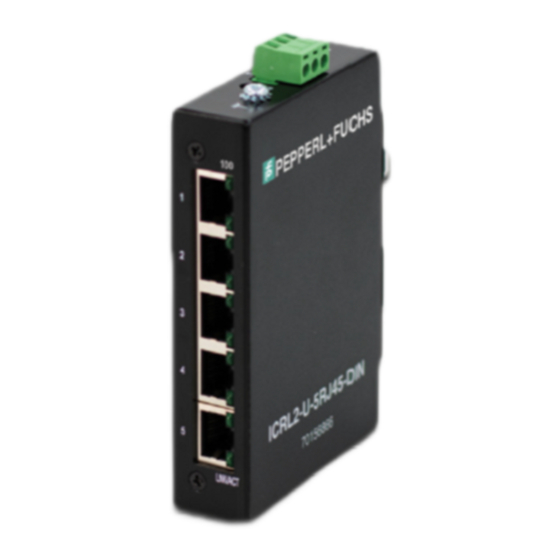
ICRL2-U-5RJ45-DIN Manual Product Overview 1. Introduction 1.1. Product Overview The ICRL2-U-5RJ45-DIN is an unmanaged Industrial Ethernet switch that is specially designed to expand reliable Ethernet connectivity to factory floors and outdoor environments with extreme temperature and climatic conditions. The ICRL2-U-5RJ45-DIN is equipped with 5 x 10/100 RJ45 Ports that are enclosed in an IP30 housing. 1.2. -
Page 6: Installation
ICRL2-U-5RJ45-DIN Manual Mounting / Dismounting - DIN Rail | Mounting the ICRL2-U-5RJ45-DIN 2. Installation ATTENTION: Please leave at least 5cm of space at the left and right of the unit for ventilation. 2.1. Mounting / Dismounting - DIN Rail ATTENTION: The ICRL2-U-5RJ45-DIN is an open type device and the ICRL2-U-5RJ45-DIN should be DIN rail mounted or wall mounted (optional) in a cabinet or enclosure and the ambient temperature should not exceed 75°C. -
Page 7: Dismounting The Icrl2-U-5Rj45-Din
ICRL2-U-5RJ45-DIN Manual Mounting / Dismounting - DIN Rail | Dismounting the ICRL2-U-5RJ45-DIN 2.1.2. Dismounting the ICRL2-U-5RJ45-DIN Press the switch from top and pull out the lower edge of the switch and then remove the switch from the DIN rail. -
Page 8: Wall Mounting The Icrl2-U-5Rj45-Din
ICRL2-U-5RJ45-DIN Manual Grounding the ICRL2-U-5RJ45-DIN | Wall Mounting the ICRL2-U-5RJ45-DIN 2.1.3. Wall Mounting the ICRL2-U-5RJ45-DIN 1. Place the switch by using mounting holes on the wall at the appropriate place. 2. The wall-mount direction can be straight or horizontal. 2.2. Grounding the ICRL2-U-5RJ45-DIN Grounding and wire routing help limit the effects of noise due to electromagnetic interference (EMI). -
Page 9: Wiring Requirements
ICRL2-U-5RJ45-DIN Manual Wiring Requirements | Wiring the Power Input 2.3. Wiring Requirements WARNING Safety measures should be taken before connecting the power cable. Turn off the power before connecting modules or wires. The correct power supply voltage is listed on the product label. -
Page 10: Connecting Devices
ICRL2-U-5RJ45-DIN Manual LED Indicators | Connecting Devices • Le calibre de fil du bornier doit être compris entre 12 et 24 AWG avec un connecteur vert, 12 ~ 22 AWG avec un connecteur gris. To insert power wire and connect the 12~48 V DC at a maximum of 0.15A DC power to the power terminal block, follow the steps below: 1. - Page 11 Twinsburg, Ohio 44087 · USA Tel. +1 330 4253555 E-mail: sales@us.pepperl-fuchs.com Asia Pacific Headquarters Pepperl+Fuchs Pte Ltd. Company Registration No. 199003130E Singapore 139942 Tel. +65 67799091 E-mail: sales@sg.pepperl-fuchs.com www.pepperl-fuchs.com DOCT-8415 Subject to modifications Copyright PEPPERL+FUCHS • Printed in Germany 2022-09...
Need help?
Do you have a question about the RocketLinx ICRL2-U-5RJ45-DIN and is the answer not in the manual?
Questions and answers