
Related Manuals for Pepperl+Fuchs Vibracon LVL-A7


Summary of Contents for Pepperl+Fuchs Vibracon LVL-A7
- Page 1 PROCESS AUTOMATION MANUAL Vibracon LVL-A7 Vibration Limit Switch Limit Switch for Liquids ISO9001...
- Page 2 Vibracon LVL-A7 With regard to the supply of products, the current issue of the following document is applicable: The General Terms of Delivery for Products and Services of the Electrical Industry, published by the Central Association of the Electrical Industry (Zentralverband Elektrotechnik und Elektroindustrie (ZVEI) e.V.) in its most recent...
-
Page 3: Table Of Contents
Vibracon LVL-A7 Content 1 Important Document Information ....3 1.1 Document Function ........3 1.2 Document Conventions . - Page 4 Vibracon LVL-A7 Content 8 Diagnostics and Troubleshooting ....30 8.1 Diagnostic Information via LED Display ....30 9 Maintenance .
-
Page 5: Important Document Information
Vibracon LVL-A7 Important Document Information Important Document Information Document Function This document contains all the information that is required in various phases of the life cycle of the device: from product identification, incoming acceptance and storage, to mounting, connection, operation and commissioning through to troubleshooting, maintenance and disposal. - Page 6 Vibracon LVL-A7 Important Document Information 1.2.2 Electrical Symbols Symbol Meaning Ground connection A grounded terminal which, as far as the operator is concerned, is grounded via a grounding system. Protective ground connection A terminal which must be connected to ground prior to establishing any other connections.
-
Page 7: Documentation
Vibracon LVL-A7 Important Document Information Documentation Note! The following document types are available in the download area of the Pepperl+Fuchs web site: www.pepperl-fuchs.com. Document type Document code Technical information TI01147O/98/EN Manual BA01285O/98/EN Certificates ZE01010O/98/EN, overfill prevention ZE01011O/98/EN, leaks Table 1.5... -
Page 8: Basic Safety Instructions
Vibracon LVL-A7 Basic Safety Instructions Basic Safety Instructions Requirements for the Personnel The personnel for installation, commissioning, diagnostics and maintenance must fulfill the following requirements: • Trained, qualified specialists must have a relevant qualification for this specific function and task •... -
Page 9: Workplace Safety
It meets general safety standards and legal requirements. It also complies with the EC directives listed in the device-specific EC Declaration of Conformity. Pepperl+Fuchs confirms this by affixing the CE mark to the device. EN - 7... -
Page 10: Product Description
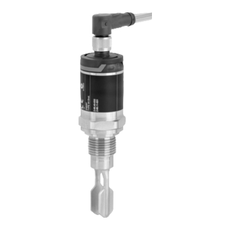
Vibracon LVL-A7 Product Description Product Description The Vibracon LVL-A7 is a limit switch for use in all liquids. It is used preferably in storage tanks, mixing vessels and pipes. Product Design The device is available in different versions which can be assembled in accordance with user specifications. -
Page 11: Incoming Acceptance And Product Identification
CRN: OF1988.5C TAG: Date: BA0xxxxF Do the data on the nameplates correspond to the order specifications on the delivery note? Table 4.1 Note! If one of these conditions is not met, please contact your Pepperl+Fuchs sales office. EN - 9... -
Page 12: Product Identification
Vibracon LVL-A7 Incoming Acceptance and Product Identification Product Identification The following options are available for identification of the measuring device: • Nameplate data • Order code with breakdown of the device features on the delivery note • Scan the 2-D matrix code (QR code) on the nameplate: all the information for the measuring device is displayed. -
Page 13: Storage And Transport
Vibracon LVL-A7 Incoming Acceptance and Product Identification Storage and Transport 4.3.1 Storage Conditions • Permitted storage temperature: -40 to +85 °C (-40 to +185 °F) • Use original packaging. 4.3.2 Handling of the Device Warning! Risk of injury caused by improper use of the device Housing or fork may become damaged or tear! •... -
Page 14: Installation
Vibracon LVL-A7 Installation Installation Installation Conditions 5.1.1 Orientation The limit switch can be installed in any position in a vessel, pipe or tank. Figure 5.1 Installation options Overfill prevention or upper level detection Lower level detection Dry running protection for pump... - Page 15 Vibracon LVL-A7 Installation 5.1.2 Switch Point The switch point (A) on the sensor depends on the orientation of the limit switch (water +25 °C (+77 °F), 1 bar (14.5 psi). Figure 5.2 Vertical and horizontal orientation, dimensions in mm (inch) 5.1.3...
- Page 16 Vibracon LVL-A7 Installation 5.1.4 Buildup Make sure that the installation socket does not exceed a certain length so that the tuning fork can project freely into the vessel. Possibilities for optimization: • A vertical orientation of the limit switch keeps buildup to a minimum.
- Page 17 Vibracon LVL-A7 Installation 5.1.5 Weld-in Adapter with Leakage Hole If installed horizontally, ensure that the leakage hole is pointing down. This allows leaks to be detected as quickly as possible. 5.1.6 Marking The marking indicates the position of the tuning fork. If installed horizontally in vessels, the marking is face up.
- Page 18 Vibracon LVL-A7 Installation 5.1.7 Installation in Pipes During installation, pay attention to the position of the fork in order to minimize turbulence in the pipe. <5 m/s (16 ft/s) Figure 5.7 Dimensions mm (inch) Figure 5.8 16 - EN...
- Page 19 Vibracon LVL-A7 Installation 5.1.8 Installation in Vessels If installed horizontally, pay attention to the position of the tuning fork to ensure that the liquid can drip off easily. The electrical connection, e. g. M12 plug, should be pointing down with the cable.
-
Page 20: Mounting The Measuring Device
Service in accordance with WHG: Prior to mounting the device, pay attention to the WHG approval documents. The documents can be found in the download area of the Pepperl+Fuchs website: www.pepperl-fuchs.com Required Tools • Open-ended wrench: only turn by the hex bolt when screwing in. -
Page 21: Post-Installation Check
Vibracon LVL-A7 Installation View, dimensions in mm (inch) Description NPT thread (ANSI B 1.20.1) Pressure and temperature (maximum): 32 mm • +40 bar (+580 psi) at +150 °C (+302 °F) Wrap in sealing material if necessary. Table 5.1 Post-Installation Check •... -
Page 22: Electrical Connection
Vibracon LVL-A7 Electrical Connection Electrical Connection Operating Modes The device has two operating modes: maximum safety (MAX) and minimum safety (MIN). By choosing the corresponding operating mode, the user ensures that the device also switches in a safety-oriented manner even in an alarm condition, e. g. if the power supply line is disconnected. - Page 23 Vibracon LVL-A7 Electrical Connection 6.2.1 Electronic Version 3-Wire DC-PNP Voltage source: non-hazardous contact voltage or Class 2 circuit (North America). M12 Plug Depending on the analysis of the switch outputs, the device works in the MAX (maximum safety) or MIN (minimum safety) mode.
- Page 24 Vibracon LVL-A7 Electrical Connection Function Monitoring with M12 Plug Using a two-channel analysis, function monitoring of the sensor can be implemented in addition to level monitoring, e. g. per relay switch, PLC, …). When both outputs are connected, the MIN and MAX outputs assume opposite states when the device is operating fault-free (XOR).
- Page 25 Vibracon LVL-A7 Electrical Connection Valve Plug, Cable Depending on the assignment of the connector or the wiring of the cable, the device works in either the MAX or MIN operating mode. Electrical connection Operating mode Valve plug – – 0.5A 0.5A...
- Page 26 Vibracon LVL-A7 Electrical Connection 6.2.2 Electronic Version 2-Wire AC/DC Not suitable for connection to low-voltage PLC inputs! Selection tool for relays Figure 6.1 Minimum rated power of the load Rated power in [W]/[VA] Operating voltage in [V] Position Supply voltage...
- Page 27 Vibracon LVL-A7 Electrical Connection Valve Plug, Cable Depending on the assignment of the connector or the wiring of the cable, the device works in either the MAX or MIN operating mode. When the cable is wired, one wire of the cable does not have any function in each of the operating modes (brown in the case of MIN, and gray in the case of MAX).
-
Page 28: Post-Connection Check
Vibracon LVL-A7 Electrical Connection Post-Connection Check • Is the device or cable undamaged (visual check)? • Do the cables comply with the requirements? • Do the cables have adequate strain relief? • Are the cable glands mounted and firmly tightened? •... -
Page 29: Commissioning
Vibracon LVL-A7 Commissioning Commissioning Installation and Function Check Before commissioning your measuring point, ensure that the post-installation and post-connection checks have been performed. • "Post-Installation Check" checklist, see page 12 • "Post-Connection Check" checklist, see page 20 Note! The function of the tuning fork can be easily tested by immersing the tuning fork in a vessel containing water. - Page 30 Vibracon LVL-A7 Commissioning 7.2.1 Function of LEDs Connection Operating modes Maximum safety (MAX) Minimum safety (MIN) Warning Fault 1 Level display unlit 2 M12 plug 3 Valve plug flashing 4 Cable Fault/warning LED colors: gn = green, ye = yellow, rd = red More information on LED display, see page 27 Table 7.2...
-
Page 31: Function Test With Test Magnet (Optional Accessory)
Vibracon LVL-A7 Commissioning Function Test with Test Magnet (Optional Accessory) Warning! Risk of injury The function test while running processes can lead to injuries. • Ensure that no dangerous processes are activated in the system. To perform a function test, hold the test magnet against the marking on the nameplate (for at least 2 seconds). -
Page 32: Diagnostics And Troubleshooting
Vibracon LVL-A7 Diagnostics and Troubleshooting Diagnostics and Troubleshooting Diagnostic Information via LED Display LED display on housing cover Malfunction Possible cause Corrective action Green LED No power supply Check connector, cable and Unlit power supply Red LED Overload or short-circuit in load •... -
Page 33: Maintenance
Vibracon LVL-A7 Maintenance Maintenance No special maintenance work is required. Cleaning Do not mount a damaged or polluted device. Clean the device if necessary. It can also be cleaned while installed (e. g. CIP = Cleaning in Place, SIP = Sterilization in Place). Take care that the device is not damaged. -
Page 34: Repair, Return, And Disposal
Pepperl+Fuchs. 10.2 Return If there is a defect, always send back the device to Pepperl+Fuchs. Take the following precautions before you return the device to Pepperl+Fuchs. • Remove all adhering residues from the device. These residues can be hazardous to health. -
Page 35: Optional Accessories
Vibracon LVL-A7 Optional Accessories Optional Accessories Note! Detailed information on accessories can be found in the technical information, see page 5. EN - 33... -
Page 36: Technical Data
Vibracon LVL-A7 Technical Data Technical Data Note! Detailed information on accessories can be found in the technical information, see page 5. 12.1 Power Supply Electronic version Supply voltage Power consumption Current consumption 3-wire DC-PNP 10 to 35 V DC < 975 mW <... - Page 37 Vibracon LVL-A7 Technical Data Electromagnetic compatibility Electromagnetic compatibility in accordance with all relevant requirements of the EN 61326 series and NAMUR recommendation EMC (NE21). For details, refer to the EC declaration of conformity. The EC declaration of conformity is available for downloading on the product detail page of the device under "Approvals+Certificates"...
-
Page 38: Process
Vibracon LVL-A7 Technical Data [°F] [°C] +158 +122 –40 –40 [°C] –20 +100 +150 [°F] –4 +122 +212 +302 +194 Figure 12.2 Derating curve: 150 °C (302 °F) : 250 mA (DC-PNP), 250 mA (AC/DC) : 150 mA (DC-PNP), 150 mA (AC/DC) - Page 39 Vibracon LVL-A7 Notes EN - 37...
- Page 40 PROTECTING YOUR PROCESS 71293234 Worldwide Headquarters Pepperl+Fuchs GmbH 68307 Mannheim · Germany Tel. +49 621 776-0 BA01285O/98/EN/03.15 E-mail: info@de.pepperl-fuchs.com For the Pepperl+Fuchs representative closest to you check www.pepperl-fuchs.com/contact www.pepperl-fuchs.com Subject to modifications Copyright PEPPERL+FUCHS • Printed in Germany 282532 DOCT-4841C 12/2016...
Need help?
Do you have a question about the Vibracon LVL-A7 and is the answer not in the manual?
Questions and answers