Table of Contents
Advertisement
Quick Links
Advertisement
Table of Contents

Related Manuals for Pepperl+Fuchs Ethernet-APL Series


Summary of Contents for Pepperl+Fuchs Ethernet-APL Series
- Page 1 ARS*-B2-IC* Ethernet-APL Rail Field Switch Hardware Manual...
- Page 2 Phone: +49 621 776 - 0 E-mail: info@de.pepperl-fuchs.com North American Headquarters Pepperl+Fuchs Inc. 1600 Enterprise Parkway Twinsburg, Ohio 44087 Phone: +1 330 425-3555 E-mail: sales@us.pepperl-fuchs.com Asia Headquarters Pepperl+Fuchs Pte. Ltd. P+F Building 18 Ayer Rajah Crescent Singapore 139942 Phone: +65 6779-9091 E-mail: sales@sg.pepperl-fuchs.com https://www.pepperl-fuchs.com...
-
Page 3: Table Of Contents
ARS*-B2-IC* Contents Introduction........................ 4 Content of this Document ................4 Target Group, Personnel ................4 Symbols Used ....................5 Product Description ....................6 Overview and Application................6 Type Codes..................... 6 Components and Dimensions ..............8 Accessories....................9 Scope of Delivery..................12 Technical data .................... -
Page 4: Introduction
ARS*-B2-IC* Introduction Introduction Content of this Document This document contains information that you need in order to use your product throughout the applicable stages of the product life cycle. These can include the following: Product identification ■ Delivery, transport, and storage ■... -
Page 5: Symbols Used
ARS*-B2-IC* Introduction Symbols Used This document contains symbols for the identification of warning messages and of informative messages. Warning Messages You will find warning messages, whenever dangers may arise from your actions. It is mandatory that you observe these warning messages for your personal safety and in order to avoid prop- erty damage. -
Page 6: Product Description
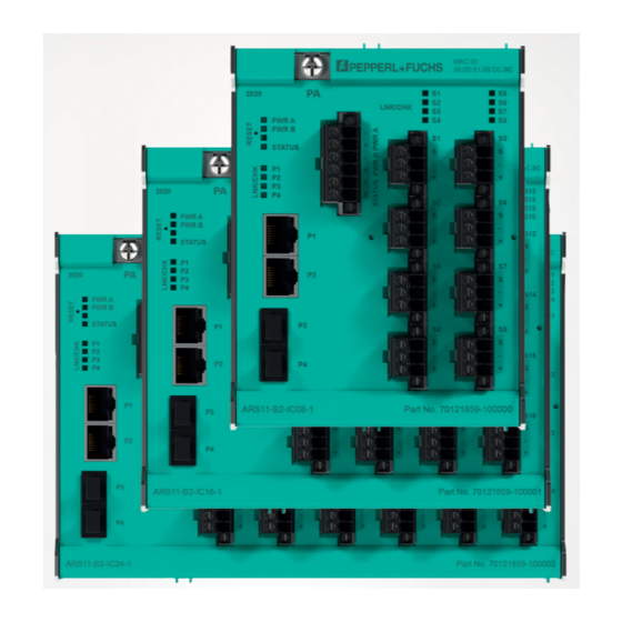
Product Description Overview and Application The Ethernet-APL series of Rail Field Switches are ruggedized, managed switches. These switches provide connectivity for Ethernet-APL and optionally PROFIBUS PA field devices to 100/1000-MBit/s industrial Ethernet networks. Port diagnostics facilitate fault finding in Ether- net-APL networks and providing information for preventive maintenance of the rail field switches and the network they are connected to. - Page 7 Spring terminal ARS1*-B2-IC08-1 ARS1*-B2-IC08-2 ARS1*-B2-IC16-1 ARS1*-B2-IC16-2 ARS1*-B2-IC24-1 ARS1*-B2-IC24-2 Table 2.1 The * asterisk stands for different firmware functionality. Refer to the datasheet or software manual for further details. Contact your Pepperl+Fuchs representative to check the availability of individual product ver- sions.
-
Page 8: Components And Dimensions
ARS*-B2-IC* Product Description Components and Dimensions Rail Field Switch with DIN Mounting Rail DIN Rail Mounting Serial No: MAC ID: yyyy LNK/CHK PWR A PWR B STATUS Dimension a ARS1*-B2-IC24*: 227 ARS1*-B2-IC16*: 173 ARS1*-B2-IC8*: 119 All dimensions in millimeters (mm) and without tolerance indication. 1 Year of production 11 Ethernet SFP port P4 2 Serial number... -
Page 9: Accessories
ARS*-B2-IC* Product Description Rail Field Switch with Wall Mounting Kit Wall Mounting Serial No: MAC ID: yyyy LNK/CHK PWR A PWR B STATUS Dimension a ARS1*-B2-IC24*: 135 Part No. ARS1*-B2-IC16*: 81 ARS1*-B2-IC8*: Dimension b ARS1*-B2-IC24*: 227 ARS1*-B2-IC16*: 173 ARS1*-B2-IC8*: 119 All dimensions in millimeters (mm) and without tolerance indication. - Page 10 Figure 2.4 The switches provide 2 sockets for small form-factor pluggable (SFP) transceiver Ethernet modules. Pepperl+Fuchs' SFP transceivers are intended to be used in applications, where extended distances are required. The SFP transceivers fulfill enhanced requirements for indus- trial use as such as installation in explosion-hazardous area, extended temperature range, and enhanced electromagnetic compatibility (EMC).
- Page 11 ■ Multi-mode fiber with 850-nm wavelength ■ Complies with a Class 1 laser product in accordance with EN 60825-1. ■ For further SFP transceiver versions contact your Pepperl+Fuchs sales representative. Protective Cover for RJ45 Sockets 13.8 11.9 Figure 2.5 To protect unused RJ45 sockets against dust or unintentional harm, protective covers are pro- vided.
-
Page 12: Scope Of Delivery
ARS*-B2-IC* Product Description Separation Wall Figure 2.7 Using the spurs in type of protection Ex ic requires clearance of 50 mm between the non-intrin- sically safe circuits as, e.g. the Ethernet ports P1 ... P4 or circuits of other equipment installed near the switch and the intrinsically safe spur terminals. - Page 13 ARS*-B2-IC* Product Description Horizontal Mounting Position Figure 2.9 Vertical Mounting Position Figure 2.10...
- Page 14 ARS*-B2-IC* Product Description Mounting position Use of SFP transceivers Ambient temperature Horizontal -40 °C ... +70 °C Horizontal -40 °C ... +65 °C Vertical -40 °C ... +55 °C Vertical -40 °C ... +55 °C Table 2.3...
-
Page 15: Installation
ARS*-B2-IC* Installation Installation General Installation Information Danger! Explosion hazard from damaged electronic components Premature wear of electronic components in a device that was previously used in a general electrical installation can cause sparks that can ignite the surrounding potentially explosive atmosphere. - Page 16 ARS*-B2-IC* Installation Figure 3.1 Position the rail field switch on the DIN mounting rail. Use the bottom hook in order to hook the electronics onto the DIN mounting rail. Move the top hook over the upper end of the DIN mounting rail until the locking mechanism engages.
- Page 17 ARS*-B2-IC* Installation Wall Mounting The accessory kit includes 2 brackets. Note When using product version with 8 Ethernet-APL spur connections, only 1 bracket is needed. Mounting wall-mounting brackets Figure 3.3 Screws for DIN mounting rail clamp TX20 screws for adapter Before installing wall-mounting bracket, remove the factory-installed DIN mounting rail clamps: To remove the DIN mounting rail clamps, loosen 3 screws each clamp.
- Page 18 ARS*-B2-IC* Installation Note In the wall-mounting kit screws for wall-mounting brackets are not included. Use the TX20 screws that are obtained by removing adapter. Fit each wall-mounting bracket with 2 screws. Fit the device to the wall with M6 screws. Inserting or Removing Fiber Optic SFP Transceiver Danger! Explosion hazard from sparking when using operating elements!
- Page 19 ARS*-B2-IC* Installation Disconnect the LC connector from the SFP transceiver. Insert a dust protection cap into the SFP transceiver. Open the bale clasp on the SFP transceiver by pushing it into downward direction with your index finger. If the bale clasp is obstructed and you cannot use your index finger to open it, use a small slot-head screwdriver to open the bale clasp.
-
Page 20: Connection Assignment
ARS*-B2-IC* Installation Connection Assignment Danger! Danger to life from incorrect installation Incorrect installation of cables and connection lines can compromise the function and the elec- trical safety of the device. Observe the permissible core cross section of the conductor. ■ When using stranded conductors, crimp wire end ferrules on the conductor ends. - Page 21 ARS*-B2-IC* Installation Spring Terminals: Cable and Connection Information Permissible core cross section: Spring terminals with flexible or rigid wires: ■ 0.5 mm ... 2.5 mm Insulation stripping length: 10 mm ... 11 mm ■ Ensure that connectors are mechanically locked ■...
-
Page 22: Grounding / Shielding
ARS*-B2-IC* Installation The switch provides a relay contact output for status indication. Spur Connection Figure 3.10 Screw terminal Figure 3.11 Spring terminal The Ethernet-APL field devices are connected through a pluggable 3-pin connector. Grounding / Shielding Danger! Explosion hazard from wrong or missing grounding! Wrong or missing grounding can cause sparks. - Page 23 ARS*-B2-IC* Installation Connecting the Ground Connection Cable Connect the ground cable to a cable lug. Position the cable lug over the grounding terminal with the cable pointing downwards. Screw the cable lug to the grounding terminal with 3 flat washers and 1 spring washer inserted between screw, lug, and terminal as illustrated: Figure 3.12 Connecting the ground connection cable...
-
Page 24: Operation
ARS*-B2-IC* Operation Operation Operating Elements Indicators The switch provides LEDs showing status and diagnosis information about the switch itself, the Ethernet ports and the spur ports. Refer to section Product Specifications for location of the LEDs. See chapter 2 LED identifica- Status / Possi- Troubleshoot- tion... - Page 25 ARS*-B2-IC* Operation Reset Button If the device is installed in explosion hazardous area, the reset button may be operated during operation. Rebooting Switch Serial No: yyyy LNK/CHK PWR A PWR A PWR B PWR B STATUS STATUS Figure 4.1 Reset button To reboot the switch, push the reset button for at least 1 second.
- Page 26 Pepperl+Fuchs Quality Download our latest policy here: www.pepperl-fuchs.com/quality www.pepperl-fuchs.com © Pepperl+Fuchs · Subject to modifications Printed in Germany / DOCT-7025...
Need help?
Do you have a question about the Ethernet-APL Series and is the answer not in the manual?
Questions and answers