urmet domus 1093 Installation And Instruction Manual
Speed dome ip 1080p
Hide thumbs
Also See for 1093:
- Quick manual (152 pages) ,
- User manual (104 pages) ,
- User manual/instructions (80 pages)

Related Manuals for urmet domus 1093


Summary of Contents for urmet domus 1093
- Page 1 Mod. 1093 DS1093-530 SPEED DOME IP 1080P Ref. 1093/655M2 INSTALLATION AND INSTRUCTION MANUAL...
-
Page 2: Table Of Contents
Index General information ..........................3 Product description..........................3 2.1.1 General features ..........................3 Opening the package ......................4 2.2.1 Contents of the package ........................4 STRUCTURE OF THIS MANUAL ..................4 ... -
Page 3: General Information
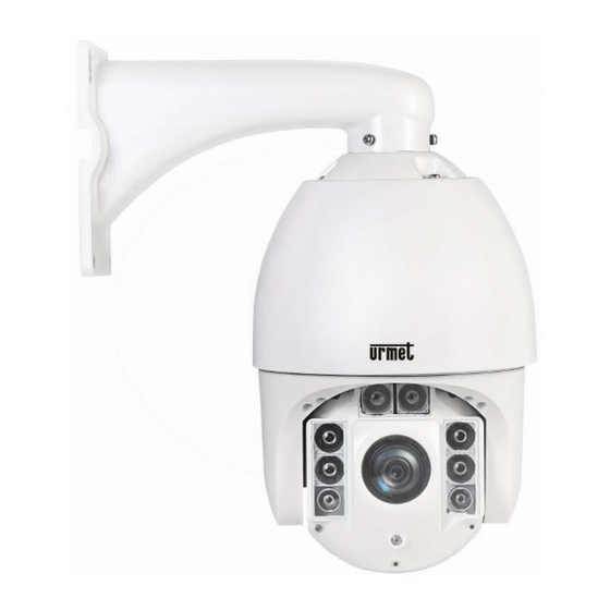
Keep this manual at hand so that you can refer to it when needed. PRODUCT DESCRIPTION The Ref.1093/655M2 speed dome ensures high performance in terms of video quality and manoeuvrability, with the possibility of taking high-quality colour images during the day and black&white images at night. -
Page 4: Opening The Package
OPENING THE PACKAGE Check that the packing and the contents are not visibly damaged. Contact the retailer immediately if parts are either missing or damaged. Do not attempt to use the device in this case. Send the product back in its original packing if it is damaged. -
Page 5: Important Safety Notes
IMPORTANT SAFETY NOTES The following important notes must be followed carefully to work the speed dome and the relative accessories in total safety. The term “video system” here means a speed dome and all components needed for its operation (e.g., power leads, supports, control board and more). - Page 6 TV set or other device. Either move the leads or re-install the device to solve the problem. Privacy and Copyright The speed dome 1093/655M2 is a CCTV system device. Recording of imagines is subject to the laws in force in your country. Recording of images protected by copyright is forbidden. ...
-
Page 7: Installation Procedure
CONFIGURATION OF A MINIMAL SYSTEM FOR USING THE SPEED DOME The 1093/655M2 cameras contain a built-in receiver that decodes the commands arriving from the control panel or the system keyboards. To function properly there must be at least one control panel. In addition to configuring operating parameters, the keypad is used to manage horizontal axis (360°... -
Page 8: Wall Installation With Power Box Ip66 Ref. 1092/708
4.1.1 WALL INSTALLATION WITH POWER BOX IP66 REF. 1092/708 Identify the camera installation point and proceed as follows: Drill holes according to the type of wall (cement, wood, etc.) and the fastening devices used (expansion screws, etc.). Fasten the connection box to the wall making sure that the wire grommets are facing downwards. Open the Power Box by unscrewing the four screws on the cover corners. -
Page 9: Operating Mode
The speed dome carries out a calibration phase by visualizing in the OSD (On Screen Display) of its output video a message containing the following information: model, protocol used, communication parameters, speed dome address and software version with a screen similar to: SPEED DOME 1093/655M2 CAMERA: CTK10IN108 ADDRESS: 1... -
Page 10: Connecting The Device
CONNECTING THE DEVICE Two installation arrangements are possible: Device connected to PC Connect the camera IP to the PC with the network cable. The power supply of the IP camera is connected to the 24 Vca power supply. Set the PC's IP address and that of the IP camera in the same network segment. If the network is under standard conditions, wait for 1 minute after power own until the IP camera establishes communication with the PC. -
Page 11: Field Of Application
FIELD OF APPLICATION The IP camera is generally used in large shopping centres, supermarkets, schools, factories, workshops, and other public places. Thanks to its high capacity to process images, the IP camera can also be used in settings that require high-definition images, like banks, and crossroads. -
Page 12: Ipwizard
IPWIZARD The software is capable of detecting the IP address of the IP camera in the LAN network. First, decompress the IPWizardIII 2.2.5 (English).zip file contained in the CD provided. IPWizardIII_2.2.5(English).zip Execute the IPWizardIII_2.2.5(English).exe software installed. IPWizardIII_2.2.5(En Launch the “IPWIZARDIII” software by selecting glish).exe : for every IP camera the IP address, Subnet Mask, Gateway, Software Version and MAC Address will appear automatically, as illustrated in the figure below. -
Page 13: Configuring The Activex Controls
CONFIGURING THE ACTIVEX CONTROLS When the IP camera connects with Internet Explorer for the first time, the user must install the plug-in. To install the plug- in, the browser protection level must be set. Select the “Tools/Internet Options/Security/Custom Level” menu and “ActiveX controls and plug-ins”... -
Page 14: Configuration Of The Ip Camera Web Page
10 CONFIGURATION OF THE IP CAMERA WEB PAGE 10.1 LIVE Open Internet Explorer and enter the IP address of the IP camera (http://192.168.1.18). The access dialogue will appear. Observe the following figure: Enter the User Name (Default User Name: admin) and Password (default: admin), then click “OK” to access the Live interface, as illustrated in the figure below. - Page 15 PTZ control In this interface the user can control the minidome, change Iris, zoom, focus, and speed for Pan and Tilt. The user can also configure or recall the Presets or stop the entire tour. Other Live interface keys: : Enables access to the settings menu of the device to set the relative personalised parameters;...
-
Page 16: Remote Settings
10.2 REMOTE SETTINGS 10.2.1 DISPLAY Basic settings Click on to access the Live interface (default) and enter the Basic Settings. Flicker Frequency:50HZ, 60HZ CVBS Output:PAL Vertical Mirror:ON, OFF Horizontal Mirror:ON, OFF Back Light:ON, OFF The compensation of back light can compensate the darkness of the subject caused by the exposure against sunlight. - Page 17 Exposure mode: Selects the exposure mode from among Scene (optimised), Shutter (automatic), and Manual Scene: Selects Outdoor or Indoor setting. Slow shutter: Selects the shutter from among Close 1/20,1/15,1/10,1/8,1/5,1/3,1/2,1. AGC: Selects the gain level- 8X, 16X, 32X, 48X, 64X. ...
- Page 18 White balance Click 【Display】→【White Balance】to access the following interface: White Balance:Auto, manual, sun light, cloudy, incandescent light, cool white fluorescent light and sodium light. Manual: Manual adjustment of the red and blue gain for the camera video. Auto: Optimisation based on current lighting conditions and the screen methods and colour calibration of the camera video.
-
Page 19: Rete (Network)
10.2.2 RETE (NETWORK) Network Click【Network】→【Network】to access the following interface: DHCP:DHCP ON/OFF. The default type is OFF. IP address: Camera IP address Subnet Mask: Camera subnet mask Default gateway: Camera default gateway Primary DNS Server/ Secondary DNS Server:DNS server of the camera Press the Save button to confirm the changes QoS (Quality of Service) Click 【Network】→【QoS】to access the following interface:... - Page 20 Click【Network】→【Port】to access the following interface: RTSP Port: the default RTSP port of the camera is 554 ONVIF Port: the ONVIF port of the camera is 8999 and cannot be changed HTTP Port: the default Web port of the camera is 80 ...
-
Page 21: Video
10.2.3 VIDEO Video Click【Video】→【Video】to access the following interface: Three video streams can be selected: Main stream, sub stream, and MJPEG For each stream the user can select: Resolution, frame rate, and image quality. For the Mainstream and Substream the user can also select: ... -
Page 22: System Parameters
CHARACTER DISPLAY Click【Video】→【Character display】to access the following interface: In this interface the user can configure up to 6 different lines of text. The user can define the text and coordinates to be displayed. 10.2.4 SYSTEM PARAMETERS SYSTEM Click【System】→【System】to access the following interface: ... - Page 23 Click【System】→【Time】to access the following interface: Here the user can select the time zone and daylight savings time Time zone: Select the time zone and daylight savings time, then press save NTP: Synchronize the time and date with the NTP server. Enter the NTP server address, the time at which the synchronisation should take place, and the interval of synchronisation (6 12 18 24 hours), then press save.
-
Page 24: Ptz Function - Preset
10.2.5 PTZ FUNCTION - PRESET Click【PTZ Function】→【Preset】to access the following interface: In this interface the user can create (Set), recall (Call), cancel (Delete) or assign a name to a PRESET (Title). 10.2.6 MANAGE USERS Click【Manage Users】to access the following interface: In this interface the user can add new users (Add User) or manage/delete existing users. -
Page 25: Local Settings
10.3 LOCAL SETTINGS Click “Local Setting” and the following interface will appear: The user can configure The saving path of the photos and their format (jpg or bmp) The saving path of the videos and their format (avi or ifv) Press the Save button to confirm the changes 10.4 ROUTER PORT-FORWARDING If the user wants to connect the IP camera via Internet, he must make the web port and the client port of the IP camera... -
Page 26: Troubleshooting
10.5 TROUBLESHOOTING ◆ Internet Explorer won’t upload and install the plug-ins. Possible cause: The IE protection level setting is too high. Solution: Set the IE protection level to minimum. ◆ After updating, the user can't connect the IP camera via Internet Explorer. Solution: Empty the IE cache. -
Page 27: How To Use The Ref. 1092/621 - 1092/693 Keyboard
11 HOW TO USE THE REF. 1092/621 - 1092/693 KEYBOARD The speed dome is ready to receive commands from the control keypads Ref. 1092/621 - 1092/693 (see figure below) after calibration. Ref. 1092/621 keyboard For instructions on using the keyboard, see the relative Usage Manual. CONTROL PANEL command syntax Controls can use the joystick, single keys or key combinations. -
Page 28: Control Panel Command Types
11.1.1 CONTROL PANEL COMMAND TYPES There are four command types. 1. Select the speed dome. 2. Move the speed dome (tilt and pan, zoom, adjust focus and iris opening, go to preset positions). 3. Adjust speed dome operation mode using menus. 4. -
Page 29: Zoom Functions
The subject is too near. 11.3.4 IRIS OPENING FUNCTIONS The iris cannot be manually opened in the 1093/655M2. 11.3.5 PRESET POSITIONS PROGRAMMING AND RECALLING The speed dome can store up to 128 panning, tilting and zooming configurations (called preset positions), each of which can be recalled at any time. -
Page 30: Function Programming Menu
95 + SHOT (1092/621) SHOT + 95 (+ ENTER) (1092/693) At this point, if no password is required for access, the following first level menu will appear on the screen: SPEED DOME 1093/655M2 3 Display Options 4 Control Options 6 Function Program... -
Page 31: Product Information Menu
Option Value Explanation Display options menu (see below). DISPLAY OPTIONS Speed dome movements programming menu (see below). CONTROL OPTIONS Preset, Vector Scan, Pattern, Sectors, Motion, Auto Scan, Pan FUNCTION PROGRAM Scan and Alarms programming and storing menu. (see below). Programming menu for the administrator (see below). SYSTEM SETUP Closes OSD menu EXIT... -
Page 32: Camera Configuration Menu (Control Options) - Settings Of Speed Dome Image And Movement.32
Option Value Explanation This operation makes it possible to assign a name to the speed dome. Pressing OPEN or IRIS+ twice accesses the screen page CAMERA NAME SETUP for naming of the device. Enabling/disabling of displaying of Pan/Tilt coordinates and zoom COORDINATES ON/OFF percentage. - Page 33 Option Value Explanation When this option is on, the movements of a subject moving underneath the camera can be followed by moving the joystick vertically only. This is possible because after reaching vertical AUTO FLIP ON/OFF position, the camera will automatically pan by 180 degrees to be repositioned and resume the tilt stroke.
-
Page 34: Function Programming Menu (Function Program) - Setting For The Functions Available On The Speed Dome
12.1.4 Function programming menu (FUNCTION PROGRAM) – setting for the functions available on the speed dome. From the first level menu, choose <FUNCTION PROGRAM> to select the functions available on the speed dome. FUNCTION PROGRAM 1 Preset 2 VectorScan 3 Pattern 4 Sector Setup 5 Motion ……………. - Page 35 12.1.4.1 PRESET submenu of the FUNCTION PROGRAMMING menu PRESET 1 Number 2 Set Preset 3 Name ______________ 4 Name Display 5 Return Option Value Explanation This option is used to select the Preset to be modified. This operation is allowed for up to 64 presettings. (Important: Another 64 presets can be commanded directly from the keyboard).
- Page 36 12.1.4.2 PROGRAM VECTORSCAN submenu of the FUNCTION PROGRAM menu The VectorScan function allows to program video surveillance sequences (VectorScan), consisting of different Presets, Pattern or also other previously created VectorScans, with programmable movement speed between positions and dwelling time. VECTORSCAN 1 Number 2 Program a VectorScan 3 Run a VectorScan...
- Page 37 12.1.4.3 PATTERN submenu of the FUNCTION PROGRAM menu A Pattern is a sequence of movements and functions that can be stored and repeated by a command of an operator or automatically. PATTERN SETUP 1 Number 2 Name ------ 3 Program 4 Name Display 5 Return Option...
- Page 38 12.1.4.4 SECTOR SETUP submenu of the FUNCTION PROGRAM menu SECTOR SETUP 1 Number 2 Name ----- 3 Pan Start POS 4 Pan End POS …………………. 5 Tilt Start POS 6 Tilt End POS 7 7 Name Display 8 Return Important note If a menu is accessed (ex: Sector Setup) and the last line of the “RETURN”...
- Page 39 12.1.4.5 MOTION submenu of the FUNCTION PROGRAM menu MOTION 1 Park Action 2 Power On Action 3 Limit Operation 4 Return Option Value Explanation This option allows the operator to select an action to be carried out if an automatic function is stopped/suspended. (See below for PARK ACTION further info and example) Allows the operator to select which specific command must be...
- Page 40 12.1.4.7 POWER ON ACTION submenu of MOTION submenu POWER ON ACTION 1 Action None 2 Number 3 Return Option Value Explanation This option allows the operator to select the action to be NONE/PRESET/VECTORSCAN/ ACTION carried out when the device is powered on. PATTERN/PANSCAN/AUTOSCAN/OFF This option allows to define in detail which single action PRESET:...
- Page 41 12.1.4.9 AUTO SCAN SETUP submenu of the FUNCTION PROGRAM This function determines a continuous rotation of the camera. AUTO SCAN SETUP 1 Auto Scan Pos Set 2 Speed Scan 3 Direction Left 4 Run 5 Return Option Value Explanation This option allows the operator to memorize the starting coordinates of the PAN and TILT sector.
- Page 42 12.1.4.11 ALARM PROGRAMMING submenu of the FUNCTION PROGRAM This menu allows the selection of the alarms enabled with the additional remote alarm system. After selecting one option the next menu of the speed dome will be displayed. ALARM PROGRAMMING 1 Number 2 Name ----- 3 Name Display...
-
Page 43: System Setup Programming Menu - Authorization/Disabling Settings For Speed Dome
12.1.5 SYSTEM SETUP programming menu – authorization/disabling settings for speed dome. A password is requited to be able to use this menu. The password is an alphanumeric combination (max. 6 digits). Select the password digits by moving the joystick in the horizontal direction. The "I" symbol indicates the digit that will be entered. - Page 44 SYSTEM SETUP 1 Master Setup 2 Operator Setup 3 Authorization 4 Restore Default 5 Return Option Value Explanation This option allows the operator to edit a first level password MASTER SETUP (max. authorization level). (See below). This option allows the operator to edit a second level OPERATOR SETUP password.
- Page 45 OPERATOR SETUP submenu of the SYSTEM SETUP menu OPERATOR SETUP 1 Password Edit 2 Operation Lock 3 Wait 4 Return Option Value Explanation This option allows the operator to edit a second level password that enables or disables specific options and functions PASSWORD EDIT available on the speed dome.
- Page 46 Option Value Explanation If enabled (ON), this option enables the password at the dome LOGIN PASSWORD ON/OFF power-up. If enabled (ON), this option allows the user to program presets. PROGRAM PRESET ON/OFF If enabled (ON), this option allows the user to use presets. CALL PRESET ON/OFF If enabled (ON), this option, allows the user to program the...
-
Page 47: Special Keyboard Commands 1092/621 - 1092/693
13 SPECIAL KEYBOARD COMMANDS 1092/621 - 1092/693 The speed dome 1093/655M2 can be programmed and operated using various keyboard short cuts. To use them, press the buttons sequence indicated in the following table. Control panel command Function Stores preset position (Preset) xxx... - Page 48 Simulates the N° 10 alarm input activation 180+SHOT/SHOT+180+ENTER Simulates the N° 11 alarm input activation 181+SHOT/SHOT+181+ENTER Simulates the N° 12 alarm input activation 182+SHOT/SHOT+182+ENTER Simulates the N° 13 alarm input activation 183+SHOT/SHOT+183+ENTER Simulates the N° 14 alarm input activation 184+SHOT/SHOT+184+ENTER Simulates the N°...
-
Page 49: Specifications
14 SPECIFICATIONS The main technical features of the speed dome Ref.1093/655M2 are summarised below. Speed dome Value Speed dome sensor module CMOS IMX322 1/2.8” 1080p Horizontal resolution Sensitivity (lux) 0.2Lux COL; 0,02Lux B/N (F1.6, 1/50s 50IRE) IR Cut mechanic filter... - Page 50 Mechanical functions Value Installation Wall mounted, bracket included Horizontal rotation angle/speed 360° (continuous) / 180°/s Vertical rotation angle/speed 0° - 90° (Flip) / 100°/s Horizontal rotation speed /°sec. 200°/s Auto flip Enable Degree of protection IP66 Remote control Value Interface RS485 Protocol Pelco-D...
- Page 51 DS1093-530 Technical area URMET S.p.A. Customer Care +39 011.23.39.810 10154 TORINO (ITALY) http://www.urmet.com VIA BOLOGNA 188/C e-mail: info@urmet.com Tel. +39 011.24.00.000 (AUTO) +39 011.24.00.300 - 323 MADE IN CHINA DS1093-530...
Need help?
Do you have a question about the 1093 and is the answer not in the manual?
Questions and answers