Table of Contents
Advertisement
Advertisement
Table of Contents
Troubleshooting

Related Manuals for HP E3800-24G-2SFP+


Summary of Contents for HP E3800-24G-2SFP+
- Page 1 HP E3800 Switches Installation and Getting Started Guide Power over Ethernet...
- Page 3 HP E3800 Switches Installation and Getting Started Guide...
- Page 4 Publication Number The only warranties for HP products and services are set forth in the express warranty statements accompanying 5998-0566 such products and services. Nothing herein should be August 2011 construed as constituting an additional warranty.
-
Page 5: Table Of Contents
HP E3800 Stacking Module ........ - Page 6 Downloading New Switch Software ......5-15 HP Customer Support Services ........5-15...
- Page 7 A Specifications Switch Specifications ......... . . A-1 Physical .
-
Page 9: Introducing The E3800 Switches
Introducing the E3800 Switches The HP E3800 switches are multiport switches that can be used to build high- performance switched networks. These switches are store-and-forward devices offering low latency for high-speed networking. The E3800 switches also support a field-replaceable Redundant Power Supply and fan tray, Power over Ethernet (PoE/PoE+) technologies, and full network management capabilities. -
Page 10: Fronts Of The Switches
Introducing the E3800 Switches Fronts of the Switches Fronts of the Switches PoE/PoE+ Switches Figure 1-1. Front of the HP E3800-24G-PoE+-2SFP+ Switch PoE, Tmp (Temperature), and Power, Test status LEDs Fault, and Locator LEDs Mode and Stacking Switch port LEDs... - Page 11 Introducing the E3800 Switches Fronts of the Switches Figure 1-3. Front of the HP E3800-24G-PoE+-2XG Switch Power, PoE, Tmp, and Test Fault, and status LEDs Locator LEDs Mode and Stacking Switch port LEDs Fan, Mdl, and PS status status LEDs...
-
Page 12: Non-Poe Switches
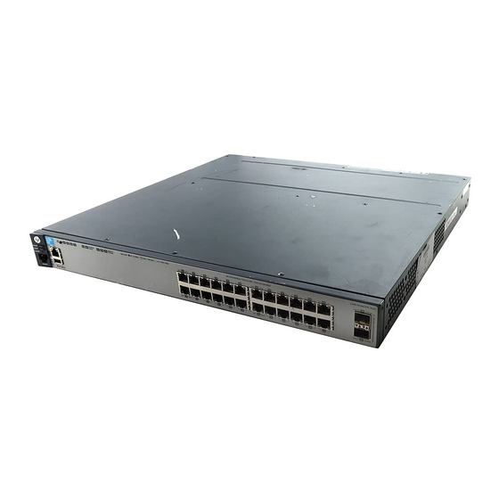
Introducing the E3800 Switches Fronts of the Switches Non-PoE Switches Figure 1-5. Front of the HP E3800-24G-2SFP+ Switch Tmp and Test status Power, LEDs Fault, and Locator Switch port LEDs Mode and Stacking Fan, Mdl, and PS LEDs status LEDs... - Page 13 Introducing the E3800 Switches Fronts of the Switches Figure 1-7. Front of the HP E3800-24G-2XG Switch Tmp and Test Power, status LEDs Fault, and Locator Switch port LEDs Mode and Stacking Fan, Mdl, and PS LEDs status LEDs status LEDs...
-
Page 14: Network Ports
Introducing the E3800 Switches Fronts of the Switches Figure 1-9. Front of the HP E3800-24SFP-2SFP+ Switch Power, Tmp and Test Fault, and status LEDs Locator LEDs Mode and Stacking Switch port LEDs Fan, Mdl, and PS status status LEDs LEDs... -
Page 15: Management Ports
Fiber (single mode) 10-Gig ER Fiber (single mode) For supported transceivers, visit www.hp.com/networking/support. – In the first textbox, type J4858 (for 100-Mb and Gigabit information), or J8436 (for 10-Gigabit information). – Select any of the products that display in the dropdown list. -
Page 16: Switch And Port Leds
Introducing the E3800 Switches Fronts of the Switches Out-of-Band Management (OOBM) Port This RJ-45 port is used to connect a dedicated management network to the switch. Auxiliary (Aux) Port An auxiliary port for processing a USB command file or downloading switch software code. - Page 17 Introducing the E3800 Switches Fronts of the Switches Switch LEDs State Meaning Test The normal operational state; the switch is not undergoing self test. (green/ The switch self test and initialization are in progress after the switch has been power orange) cycled or reset.
- Page 18 Introducing the E3800 Switches Fronts of the Switches Switch LEDs State Meaning LED Mode Indicates the port LEDs are displaying network activity information. View (green) Indicates port Mode LEDs are lit for ports in Full Duplex Mode. Off indicates half duplex. Indicates the port Mode LEDs are displaying the connection speed at which each port is operating.
- Page 19 Introducing the E3800 Switches Fronts of the Switches Switch LEDs State Meaning Switch temperature is normal. (green/ Fast blink An over temperature condition has been detected. Orange) orange** Aux Port Used for processing a USB command file or downloading switch software code. (green) * The blinking behavior is an on/off cycle once every 1.6 seconds, approximately.
- Page 20 Introducing the E3800 Switches Fronts of the Switches Table 1-4. Stacking-Related Switch and Port LED Behavior Switch LEDs State Meaning LED Mode For switches in a stack, the LED mode indications are the same as for standalone switches (see Table indicator 1-3), but all the switches in the stack are coordinated and all show the same LED mode.
-
Page 21: Led Mode Select Button And Indicator Leds
Introducing the E3800 Switches Fronts of the Switches LED Mode Select Button and Indicator LEDs The operation of the Mode LED is controlled by the LED Mode select button, and the current setting is indicated by the LED Mode indicator LEDs near the button. -
Page 22: Reset And Clear Buttons
Introducing the E3800 Switches Fronts of the Switches Reset and Clear Buttons The Reset and Clear buttons are located behind the front panel (to protect them from being pushed accidentally) and are accessible through small holes in the lower left corner of the front panel. Use pointed objects, such as unbent paper clips, to push them. -
Page 23: Backs Of The Switches
Module Slot Each of the E3800 switches has one module slot that can accept the HP E3800 Stacking Module that provides high-speed connectivity to other E3800 switches. Only the E3800 switches support this module. -
Page 24: Fan Tray
“Replacing the Fan Tray” on page 4-2. HP E3800 Stacking Module The HP E3800 4-port Stacking Module (J9577A) is a component you can add to an HP E3800 Switch to provide high-speed stacking connections to other E3800 switches. See “Stacking Information and Topologies” on page... -
Page 25: Stacking Module Leds
Introducing the E3800 Switches HP E3800 Stacking Module Stacking Module LEDs The following LEDs are located on the E3800 Stacking Module bulkhead. These LEDs are only viewable in the rear of the switch on the module itself. Figure 1-14. Stacking Module LEDs... -
Page 26: Switch Features
E3800-48G-4SFP+-PoE+ switches are IEEE 802.3at standard compliant and provide up to 30 W per port to power IP phones, wireless access points, web cameras, and more. For more information, see the HP Power over Ethernet (PoE/PoE+) Planning and Implementation Guide which is on the HP Web site, www.hp.com/networking/support. - Page 27 Web browser interface—an easy to use built-in graphical interface that can be accessed from common web browsers. • HP Professional Management Center (PMC)—an SNMP-based, graphical network management tool that you can use to manage your entire network. This product is included with your new switch.
- Page 28 Introducing the E3800 Switches Switch Features 1-20...
-
Page 29: Installing The Switch
HP X410 E-Series 1U Universal Rack Mounting Kit (J9583A). Optionally, it can also be mounted in an HP 10K rack using the HP 1U RK MT SWITCH 10K ALL rail kit, part number 356578-B21 and shelf kit AB469A, HP rx 16/26 Factory Rackmount Shelf Kit (both kits must be used, otherwise you will void the warranty). -
Page 30: Installation Procedures
Installing the Switch Installation Procedures Power cord, one of the following ■ Region All 3800 Switches 8121-0857 Australia/New Zealand China 8120-1034 Continental Europe 8120-5336 Denmark 8120-5340 Japan 8120-5342 Switzerland 8120-5339 United Kingdom/Hong Kong/Singapore 8120-5334 United States/Canada/Mexico 8121-0973 South Africa and India 8120-5341 Argentina 8120-8375... - Page 31 Installing the Switch Installation Procedures (Optional) Install the module (page 2-8). 2-10). The Switch can be mounted in a 19-inch Mount the switch (page telco rack, in an equipment cabinet, or on a horizontal surface. (Optional) Install the stacking cables (page 2-14).
- Page 32 ■ If the switch is to be shipped in a rack, it can be mounted and shipped in many four post racks using HP X410 E-Series 1U Universal Rack Mounting Kit (J9583A). Ensure the power source circuits are properly grounded, then use the ■...
-
Page 33: Prepare The Installation Site
Installing the Switch Installation Procedures 1. Prepare the Installation Site Cabling Infrastructure - Ensure the cabling infrastructure meets the necessary network specifications. See “Cabling and Technology Information” in the appendices for more information. Installation Location - Before installing the switch, plan its location and orientation relative to other devices and equipment: •... -
Page 34: Verify The Switch Boots Correctly
Installing the Switch Installation Procedures 2. Verify the Switch Boots Correctly N o t e For steps 2 and 3, if an E3800 switch is powered on for the first time without a stacking module installed, stacking will be disabled and that will be saved in the switch's running configuration. - Page 35 Installing the Switch Installation Procedures Check the LEDs on the switch as described below. Figure 2-3. Example of an HP E3800 24-port non-PoE switch Switch port LEDs Power and Test LED Fault LEDs Figure 2-4.Example of an HP E3800-48-port PoE+ switch...
-
Page 36: Optional) Install The Stacking Module
Installing the Switch Installation Procedures • The port LEDs on the front of the switch go into their normal operational mode: – If the ports are connected to active network devices, the port Link LEDs are on, and the port Mode LEDs behave according to the LED Mode selected. - Page 37 Installing the Switch Installation Procedures Verifying the Module is Installed Correctly Observe the Module Status (Mdl) and Fault LEDs on the front of the switch to verify the module is installed properly. Figure 2-6. Location of Module Status LEDs Module (Mdl) Status Fault LED If the module is installed properly and the switch is powered on, the module undergoes a self test that takes a few seconds.
-
Page 38: Mount The Switch
■ on a horizontal surface For other mounting options contact your local HP authorized network reseller or HP representative. Rack or Cabinet Mounting These switches are designed to be mounted in any EIA-standard 2-post 19- inch telco rack or 4-post communication equipment cabinet. - Page 39 Installing the Switch Installation Procedures N o t e The mounting brackets have multiple mounting holes and can be rotated allowing for a wide variety of mounting options. These include mounting the switch so its front face is flush with the face of the rack as shown in the illustration, or mounting it in a more balanced position.
- Page 40 Installation Procedures Rack Mounting the E3800 switch in a 4-post rack Using the (J9583A) HP X410 E-Series 1U Universal Rack Mounting Kit, use a #1 Phillips (cross-head) screwdriver and attach the slider brackets to the switch with the included 8-mm M4 screws.
- Page 41 Installing the Switch Installation Procedures Figure 2-11. Installing the switch Horizontal Surface Mounting Place the switch on a table or other horizontal surface. The switch comes with rubber feet in the accessory kit that can be used to help keep the switch from sliding on the surface.
-
Page 42: Optional) Install Stacking Cables
Installing the Switch Installation Procedures 5. (Optional) Install Stacking Cables N o t e Hot swapping stacking cables is supported. You can install or remove a stacking cable with the switch powered on. a. Slide in the stacking cable connector until it clicks into place. Pull on the cable connector (not the tab) to make sure that it is fully latched. -
Page 43: Optional) Install Transceivers
If the transceiver is removed before the authentication completes a self test failure will be reported. W A R N I N G The HP transceivers are Class 1 laser devices. Avoid direct eye exposure to the beam coming from the transmit port. Figure 2-13. Installing a transceiver. -
Page 44: Connect The Switch To A Power Source
Installing the Switch Installation Procedures Removing the transceiver: N o t e Always disconnect the network cable from the transceiver before removing it from the switch. Depending on when the transceiver was purchased, it may have either of three different release mechanisms: a plastic tab on the bottom of the transceiver, a plastic collar around the transceiver, or a wire bail. -
Page 45: Optional) Install A Second Power Supply
There are two types of power supplies that can be installed: ■ HP 400W Power Supply, (J9581A, HP X311 400W 100-240VAC to 12VDC PS) used with the non-PoE switches and is keyed so that it cannot be used in the PoE/PoE+ switches. -
Page 46: Optional) Connect A Management Console
Installing the Switch Installation Procedures 9. (Optional) Connect a Management console The switch has a full-featured, easy to use console interface for performing switch management tasks including: ■ Monitor switch and port status and observe network activity statistics. Modify the switch’s configuration to optimize switch performance, ■... - Page 47 Press any key to display the switch console to PC command (CLI) prompt; for example: HP E3800# c. Continue the console session to configure the switch by following the procedure in “Minimal Configuration Through the Out-of-Band Console Connection” on page 3-2.
- Page 48 Installing the Switch Installation Procedures I m p o r t a n t You must use the out-of-band console connection to minimally configure the switch with an IP address and subnet mask before you can use an in-band or out-of-band networked connection to manage the switch.
-
Page 49: Connect The Network Cables
Installing the Switch Installation Procedures 10. Connect the Network Cables Connect the network cables, described under “Cabling Infrastructure” (page 2-5), from the network devices or your patch panels to the fixed RJ-45 ports on the switch or to any transceivers installed in the switch. Using the RJ-45 Connectors To connect: Figure 2-16. - Page 50 Installing the Switch Installation Procedures Connecting a fiber cable To connect: Figure 2-17. Connecting fiber optic cable 1. Remove the dust covers from the cable connectors and the port. 2. Aligning the notches on the cable connectors with the slots of the port, press the cable connector into the port until it snaps into place.
-
Page 51: Stacking Information And Topologies
Stacking Information and Topologies Stacking Information and Topologies The E3800 switches support the HP FlexChassis Mesh feature for stacking the switches. When E3800 Stacking Modules (J9577A) are installed in the switches, any combination of up to ten E3800 switches can be stacked together via high-speed backplane cables to form a single extended virtual switch. - Page 52 Installing the Switch Stacking Information and Topologies Chain Topologies Up to 10 switches may be stacked in an open-ended chain with single cables between each pair of switches. N o t e Chain topologies are not recommended because a single failure (switch, stacking module, or cable) will cause switch-to-switch communication failures between switches that are located on opposite sides of the failure.
- Page 53 Installing the Switch Stacking Information and Topologies Figure 2-18. Typical chain topology Cable connection examples for stacked chains are illustrated in Figure 2-19. Figure 2-19. Cable connection examples for chain topologies 2-switch chain 3-switch chain 5-switch chain 2-25...
- Page 54 Installing the Switch Stacking Information and Topologies Ring Topologies Up to 10 switches may also be connected in closed ring topologies. Ring topologies afford some protection from a single failure because communications between the switches continues, in a direction away from the failure.
- Page 55 Installing the Switch Stacking Information and Topologies Mesh Topologies Two to five switches may be stacked using mesh topologies. In mesh topologies, every switch in the stack is connected to every other switch in the stack. Hence, with four stacking ports on the Stacking Module, the maximum number of switches that can be meshed together is limited to five.
- Page 56 Installing the Switch Stacking Information and Topologies Cable connection examples for stacked redundant and meshed topologies are illustrated in Figure 2-23. Figure 2-23. Cable connection examples for Redundant and Meshed Topologies 2-switch mesh 3-switch mesh 4-switch mesh 5-switch mesh 2-28...
-
Page 57: Sample Network Topologies
This section shows a few sample network topologies in which the switch is implemented. For more topology information, visit the product’s Web site at www.hp.com/networking/support. The switch is designed to be used primarily as a desktop switch to which end nodes, printers and other peripherals, and servers are directly connected, as shown in the following illustration. - Page 58 Figure 2-25. Example as a Segment Switch Server with Gigabit Ethernet NIC Switch E3800 To Backbone Fast Ethernet Switch Ethernet Switch hp pr ocur ve hp pr ocur ve s w itch 2650 s w itch 2650 J 4899A J 4899A A ct P ower...
- Page 59 Installing the Switch Sample Network Topologies In the illustration above, two “Fast” Ethernet hubs with PCs, printers, and local servers attached, are both connected to a Switch. The devices attached to the two hubs can now communicate with each other through the switch. They can also all communicate with the server that is connected to a 1000Base-T port on the switch.
- Page 60 Installing the Switch Sample Network Topologies As shown in Figure 2-20, the IP telephones have been inserted in between the E3800-PoE+ switch and the PCs, and a WAP has been connected to the E3800- PoE+ switch. Only devices directly connected to the PoE+ switches can receive PoE/PoE+ power.
- Page 61 The simpler desktop and segment networks shown in the previous two examples can easily be combined and expanded. For example, you could use an HP E5406 zl Switch to interconnect each of your smaller switched workgroups to form a larger switched network. All the devices in this network can communicate with each other.
- Page 62 Installing the Switch Sample Network Topologies 2-34...
-
Page 63: Getting Started With Switch Configuration
For more information on using the switch console and the other switch management interfaces: the web browser interface and the SNMP manage- ment tool, HP ProCurve Manager, please see the Management and Configu- ration Guide, which is on the HP Web site at www.hp.com/networking/support. -
Page 64: Minimal Configuration Through The Console Port Connection
“Setting Up a Console Connection” on page 2- The E3800 command-line prompt should be displayed on the console screen, typically with the switch model number; for example: HP E3800# 3. At the prompt, enter the setup command to display the Switch Setup screen. - Page 65 8. Press Enter, then S (for Save). The following fields are displayed in the Setup screen. For more information on these fields, see the Management and Configuration Guide, which is on the HP Web site at www.hp.com/networking/support. Parameter Default System Name blank Optional;...
-
Page 66: Where To Go From Here: Networked Connections
SNMP-based network management station using a tool such as ProCurve ■ Manager. For more information on these management interfaces and all the features that you can configure on the switch, refer to the Management and Configuration Guide for your switch on the HP Web site. - Page 67 “Using the IP Address for Remote Switch Management” on page 3- 6 and the Management and Configuration Guide for your switch at www.hp.com/networking/support. M a n a g e m e n t An E3800 Switch can simultaneously support one out-of-band serial console...
-
Page 68: Using The Ip Address For Remote Switch Management
Press a key, and you will then see the switch console command (CLI) prompt, for example: HP E3800# Enter help or ? to see a list of commands that can be executed at the prompt. Entering any command followed by help provides more detailed context help information about the command. - Page 69 The following illustration shows a typical web browser interface screen. Figure 3-2. Web browser interface screen For more information on using the web browser interface, see the Manage- ment and Configuration Guide, which is on the HP Web site at www.hp.com/ networking/support.
-
Page 71: Replacing Components
The stacking module is not hop swappable. The switch must be powered off before installing or replacing the module. C a u t i o n The HP E3800 switches and its components are sensitive to static discharge. Use an antistatic wrist strap and observe all static precautions when replacing components. -
Page 72: Replacing The Fan Tray
Replacing Components Replacing the Fan Tray Replacing the Fan Tray The fan tray is hot swappable. Replacing the fan try can be done with the switch powered on. When a fan fails the Fan Status LED on the switch will blink simultaneously with the switch Fault LED. -
Page 73: Replacing The Power Supply
Replacing Components Replacing the Power Supply Replacing the Power Supply If the E3800 switch is configured with redundant power supplies, the switch will not suffer any loss of traffic or performance if a power supply fails. Replace the failed component as soon as possible. The PS (Power Supply) LED will blink simultaneously with the switch Fault LED indicating a power supply has failed. -
Page 74: Replacing The Stacking Module
Replacing Components Replacing the Stacking Module Replacing the Stacking Module The E3800 Stacking Module is not hot swappable. The switch must be powered off before replacing the module. When a stacking module fails, the Module Status (Mdl) LED on the front of the switch and the Module Status LED on the module will blink orange simultaneously with the switch Fault LED. -
Page 75: Troubleshooting
HP Professional Management Center (HP PMC), the SNMP-based network management tool. For more information, see the chapter “Troubleshooting”... -
Page 76: Basic Troubleshooting Tips
If you no longer experience the problems, the new topology is probably at fault. Sample topologies are shown at the end of chapter 2 in this book, and some topology configuration guidelines can be found online at the HP Web site, www.hp.com/networking/support. - Page 77 Spanning Tree can be enabled through the switch console, the web browser interface, or HP ProCurve Manager. The E3800 switches also support Trunking, which allows multiple network cables to be used for a single network connection without causing a data path loop.
-
Page 78: Diagnosing With The Leds
Troubleshooting Diagnosing with the LEDs Diagnosing with the LEDs ■ Table 5-1 shows LED patterns on the switch that indicate switch problem conditions. ■ Table 5-2 shows LED patterns on the switches and on stacking modules in a stack that indicate stack-related problem conditions. Check in the tables for the LED pattern you see on your switch and stacking module. - Page 79 A switch Try power cycling the switch. If the fault indication reoccurs, the switch may have failed. hardware failure Call your HP authorized LAN dealer, or use the electronic support services from HP to get has occurred. All assistance. See “HP Customer Support Services”...
- Page 80 – For twisted-pair connections to the fixed 10/100 or 10/100/1000 ports, if the port is configured to “Auto” (auto negotiate), either straight-through or crossover cables can be used because of the switch’s “HP Auto-MDIX” feature and the Auto MDI/ MDI-X feature of the 10/100/1000-T port.
- Page 81 Spanning For software troubleshooting tips, see the chapter “Troubleshooting” in the Management Tree, LACP, or www.hp.com/networking/support and Configuration Guide for your switch at IGMP features. Make sure also, the device at the other end of the connection is indicating a good link to the switch.
- Page 82 Troubleshooting Diagnosing with the LEDs Table 5-2. Stacked Switch and Stacking Module LED Error Indicators LED Pattern Indicating Problems Module Diag Tips Fault Mdl Status ** Switch Port LEDs Port Link LEDs † blink orange † † see tip 2 blink orange blink orange †...
- Page 83 If necessary to resolve the problem, contact your HP authorized stacking cable LAN dealer, or use the electronic support services from HP to – the stacking module or switch at the get assistance. See “HP Customer Support Services”...
- Page 84 Advance Traffic Management Guide for more information. also be blinking orange simultaneously. If necessary to resolve the problem, contact your HP authorized LAN dealer, or use the electronic support services from HP to get assistance. See “HP Customer Support Services” on page 5-15.
-
Page 85: Proactive Networking
Troubleshooting Proactive Networking Proactive Networking The HP E3800 switches have built-in management capabilities that proactively help you manage your network, they include: finding and helping you fix the most common network error conditions ■ (for example, faulty network cabling, and non-standard network topolo- gies) ■... -
Page 86: Hardware Diagnostic Tests
Troubleshooting Hardware Diagnostic Tests Hardware Diagnostic Tests Testing the Switch by Resetting It If you believe the switch is not operating correctly, you can reset the switch to test its circuitry and operating code. To reset a switch, either: ■ unplug and plug in the power cord (power cycling) ■... -
Page 87: Testing Twisted-Pair Cabling
Telnet connection, or from the switch’s web browser interface. For more information, see the Management and Configuration Guide for your switch at www.hp.com/networking/support. These tests can also be performed from an SNMP network management station running a program that can manage the switch, for example, ProCurve Manager. -
Page 88: Restoring The Factory Default Configuration
For both the save and restore processes, you can use the console copy command. For more information on this command, see www.hp.com/ the Management and Configuration Guide for your switch at networking/support. -
Page 89: Downloading New Switch Software
Additionally, your HP authorized network reseller can provide you with assistance, both with services that they offer and with services offered by HP. Before Calling Support Before calling your networking dealer or HP Support, to make the support... - Page 90 Troubleshooting HP Customer Support Services 5-16...
-
Page 91: Switch Specifications
Specifications Switch Specifications Physical Product Weight Width Depth Height E3800-24G-PoE+-2SFP+ Switch (J9573A) 7.2 kg (15.90 lb ) E3800-48G-PoE+-4SFP+ Switch (J9574A) 7.6 kg (16.85 lb) E3800-24G-PoE+-2XG Switch (J9587A) 7.5 kg (16.45 lb) E3800-48G-PoE+-4XG Switch (J9588A) 7.8 kg (17.25 lb) 430 mm (16.9 in) E3800-24G-2SFP+ Switch (J9575A) 6.9 kg (15.25 lb) 442.5 mm (17.4 in) -
Page 92: Environmental
Specifications Switch Specifications Environmental HP E3800 Switches Environmental 0°C to 55°C (32°F to 131°F) Operating Temperature Relative Humidity: 15% to 95% at 40°C (104°F) non-condensing Non-Operating -40°C to 70°C (-40°F to 158°F) Temperature: Non-Operating Relative 15% to 90% at 65°C (149°F) -
Page 93: Safety
Switch Specifications Safety Complies with: ■ EN60950-1 CSA22.2 No. 60950-1 ■ UL60950-1 ■ ■ IEC60950-1 EN 62479:2010 ■ EN 60825-1:2007 / IEC 60825-1:2007 Class 1 ■ ■ Class 1 Laser Products / Laser Klasse 1 Connectivity Standards Table A-1. Technology Standards and Safety Compliance Laser safety information Technology Compatible with these IEEE... -
Page 94: Stacking Module Specifications
Specifications Stacking Module Specifications Table A-1. Technology Standards and Safety Compliance (Continued) Laser safety information Technology Compatible with these IEEE EN/IEC standard SFP+ standards compliance ("mini-GBIC") Lasers Lasers 10-Gig Direct (not an IEEE standard) Attach Class 1 Laser Product 10-Gig SR IEEE 802.3ae 10GBASE-SR EN/IEC 60825 Laser Klasse 1... -
Page 95: B Cabling And Technology Information
Cabling and Technology Information This appendix includes switch connector information and network cable information for cables that should be used with the HP switches. N o t e Incorrectly wired cabling is a common cause of problems for LAN communications. HP recommends that you work with a qualified LAN cable installer for assistance with your cabling requirements.. - Page 96 Cabling and Technology Information Note on 1000BASE-T Cable Requirements The Category 5 networking cables that work for 100BASE-TX connections should also work for 1000BASE-T, as long as all four-pairs are connected. But, for the most robust connections, you should use cabling that complies with the Category 5e specifications, as described in Addendum 5 to the TIA-568-A standard (ANSI/ TIA/EIA-568-A-5).
-
Page 97: Technology Distance Specifications
Cabling and Technology Information link to drop if moved. Therefore, HP recommends using Category 6A patch cables, or using cable management options to tie down (dress) the Category 6 patch cables so they cannot move. Technology Distance Specifications Table B-2. Technology Distance Specifications... -
Page 98: Mode Conditioning Patch Cord
Cabling and Technology Information Table B-2. Technology Distance Specifications(Continued) Technology Supported cable type Multimode fiber Supported distances modal bandwidth 10-Gig LR single mode fiber 2 - 10,000 meters 10-Gig ER single mode fiber 2 - 40,000 meters Cat 6 cabling requires TIA TSB-155A testing for 500 MHz operation and ANEXT. For distances less than 20km, a 10dB attenuator must be used. -
Page 99: Installing The Patch Cord
Installing the Patch Cord As shown in the illustration below, connect the patch cord to the HP transceiver with the section of single mode fiber plugged in to the Tx (transmit) port. Then, connect the other end of the patch cord to your network cabling patch panel, or directly to the network multimode fiber. -
Page 100: Twisted-Pair Cable/Connector Pin-Outs
Cabling and Technology Information Twisted-Pair Cable/Connector Pin-Outs Twisted-Pair Cable/Connector Pin-Outs Auto-MDIX Feature: The 10/100/1000-T ports support the IEEE 802.3ab standard, which includes the “Auto MDI/MDI-X” feature. In the default configuration, “Auto”, the ports on the Switch 3500 all automatically detect the type of port on the connected device and operate as either an MDI or MDI- X port, whichever is appropriate. -
Page 101: Connections
Straight-Through Twisted-Pair Cable for 10 Mbps or 100 Mbps Network Connections Because of the HP Auto-MDIX operation of the 10/100 ports on the switch, for all network connections, to PCs, servers or other end nodes, or to hubs or other switches, you can use straight-through cables. -
Page 102: Connection
Crossover Twisted-Pair Cable for 10 Mbps or 100 Mbps Network Connection The HP Auto-MDIX operation of the 10/100 ports on the switch also allows you to use crossover cables for all network connections, to PCs, servers or other end nodes, or to hubs or other switches. -
Page 103: Straight-Through Twisted-Pair Cable For 1000 Mbps Network
Cabling and Technology Information Twisted-Pair Cable/Connector Pin-Outs Straight-Through Twisted-Pair Cable for 1000 Mbps Network Connections 1000Base-T connections require that all four pairs or wires be connected. Cable Diagram N o t e Pins 1 and 2 on connector “A” must be wired as a twisted pair to pins 1 and 2 on connector “B”. - Page 104 Cabling and Technology Information Twisted-Pair Cable/Connector Pin-Outs B-10...
-
Page 105: Index
Index Numerics 10/100Base-TX ports cabinet location on switch … 1-2 mounting the switch in … 2-10 1000Base-BX … B-3 cables fiber-optic cable specifications … B-3 connecting cables to switch ports … 2-21 1000Base-LH … B-3 effects of non-standard cables … 5-2 fiber-optic cable specifications …... - Page 106 console Fault LED checking messages during behavior during self test … 2-7 troubleshooting … 5-12 location on switch … 1-2 configuring IP address for Telnet access … 3-1 showing error conditions … 5-4 displaying CLI prompt … 2-19 fault LED … 1-8 features …...
- Page 107 installation stacking cable … 2-14 IP address MDI-X to MDI network cable … B-7, B-9 configuring … 3-3 MDI-X to MDI-X network cable … B-8 required for networked management mesh sessions … 3-1 stacking topology … 2-27 Mode LEDs … 1-9 module install or remove …...
- Page 108 pin-outs replacing components twisted-pair cables … B-6 power supply PoE LEDs … 1-9 replacing power supply … 4-3 PoE/PoE+ replacing hardware operation … 2-17 fans … 4-2 port configuration Reset button checking when troubleshooting … 5-3 location on switch … 1-2 Port LED View restoring factory default configuration …...
- Page 109 chain … 2-24 testing mesh … 2-27 checking the console messages … 5-12 ring … 2-26 checking the LEDs … 5-12 stacking cable diagnostic tests … 5-12 install or remove … 2-14 end-to-end communications … 5-13 straight-through cable link test … 5-13 pin-out …...
- Page 110 twisted-pair ports Auto-MDIX feature … B-6 Usr LEDs … 1-9 wiring rules for twisted-pair cables … B-6 6 – Index...
- Page 112 © Copyright 2011 Hewlett-Packard Development Company, L.P. The information August 2011 contained herein is subject to change without notice. The only warranties for HP products and services are set forth in the express warranty statements accompanying such products and services. Nothing herein should be construed as constituting an additional warranty.
Need help?
Do you have a question about the E3800-24G-2SFP+ and is the answer not in the manual?
Questions and answers