Table of Contents
Advertisement
Advertisement
Table of Contents
Troubleshooting

Related Manuals for HP E2620


Summary of Contents for HP E2620
- Page 1 HP E2620 Switches Installation and Getting Started Guide Power over Ethernet...
- Page 3 HP E2620 Switches Installation and Getting Started Guide...
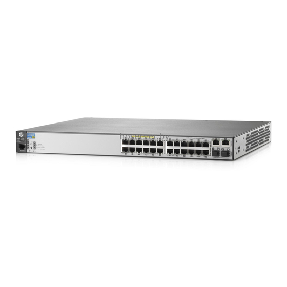
- Page 4 Applicable Products accompanying such products and services. Nothing herein should be construed as constituting an additional warranty. HP shall not be liable for technical or editorial errors or omissions contained herein. HP E2620-24 Switch (J9623A)
-
Page 5: Table Of Contents
Rack or Cabinet Mounting ....... . 2-9 Rack Mounting the E2620-PoE+ switches ....2-10 Rack Mounting the Non-PoE+ Switches . - Page 6 6. Installing or removing SFP transceivers (mini-GBICs) ..2-17 Installing the SFP transceivers: ......2-17 Removing the SFP transceiver .
- Page 7 Downloading New Switch Software ......4-13 HP Customer Support Services ........4-13 Before Calling Support .
- Page 8 B Cabling and Technology Information Cabling specifications ........B-1 Technology distance specifications .
- Page 9 D Recycle Statements Waste Electrical and Electronic Equipment (WEEE) Statements ..D-1 Index...
- Page 10 viii...
-
Page 11: Introducing The Switch
Introducing the Switch The HP E2620 Switches are multiport switches that can be used to build high- performance switched workgroup networks. These switches are store-and- forward devices that offer low latency for high-speed networking. The non- PoE and PPoE+ switches support Redundant power supply (HP 600 RPS/ EPS). - Page 12 Introducing the Switch Throughout this manual, these switches will be referred to as the E2620 Switches and the E2620-PoE+ Switches. ■ The E2620 Switches, have either 24 or 48 auto-sensing 10/100Base-TX RJ- 45 ports with four Gigabit Uplink ports, two RJ-45 and two mini-GBIC (Small Form Factor Pluggable (SFP)) slots.
- Page 13 (Partial PoE+) switch provides 24 Ethernet ports, 12 of which can supply PoE+ power). All of the Switch E2620-PoE+ ports can provide up to 30 watts (or 4 ports at 30 watts, or 8 ports at 15.4 watts on the E2620-24-PPoE+) of PoE+ power to connected devices.
- Page 14 These switches can be directly connected to computers, printers, and servers to provide dedicated bandwidth to those devices, and you can build a switched network infrastructure by connecting the switch to hubs, other switches, or routers. In addition, the E2620 Switches offer full network management capabilities.
-
Page 15: Front Of The Switch
Introducing the Switch Front of the Switch Front of the Switch Power RPS, Fan and Test HP E2620-48 Switch (J9626A) Switch port LEDs and Fault Status LEDs LEDs LED Mode select button Reset and Clear Uplink ports Console 10/100Base-TX RJ-45 ports... -
Page 16: Network Ports
■ Two RJ-45 10/100/1000Base-T ports for high speed uplink. Two mini-GBIC (SFP) slots for fiber uplinks. ■ LEDs On the E2620 Switches, there are three groupings of LEDs: switch status LEDs (Table 1-2) ■ port LEDs... - Page 17 Introducing the Switch Front of the Switch Switch LEDs State Meaning Locator The Locator LED is used to locate a specific switch in an area full of Flashing switches. The LED can be set to be on solid or flash for a specified number (blue) of minutes (1-1440).
- Page 18 The flashing behavior is an on/off cycle once every 0.8 seconds approximately, a fast flash. The flashing behavior is an on/off cycle once every 1.6 seconds approximately, a slow flash. HP E2620-24-PoE+ (J9625A) and HP E2620-48-PoE+ Switch (J9627A) Switches only. See the HP Redundant and/or External Power Supply Installation and Getting Started Guide for information on the LED behavior of the external power supplies.
-
Page 19: Port Leds
• the mini-GBIC is not supported by the current software • the mini-GBIC is not a genuine HP Mini-GBIC and is not supported • the mini-GBIC is an “A” version in a switch that requires a “B” version or later. -
Page 20: Led Mode Select Button And Indicator Leds
LED Mode Select Button and Indicator LEDs To optimize the amount of information that can be displayed for each of the switch ports in the limited space available, the E2620 Switches use multiple- display LEDs for each port. The non-PoE+ switches, have two... -
Page 21: Reset Button
Table 1-4. Multiple-Display Port LEDs Switch LEDs State Meaning All E2620 Switches Port LED View Indicates the Port LEDs are displaying network activity information. indicator LEDs Indicates the Port LEDs are lit for ports that are in full-duplex mode. 3 green LEDs) -
Page 22: Console Port
Introducing the Switch Back of the Switch Console Port This port is used to connect a console to a E2620 Switches by using the RJ-45 to DB9 cable, supplied with the switch. This connection is described under “8. (Optional) Connect a Console to the Switch” on page 25 in chapter 2, “Installing the Switch.”... -
Page 23: Rps And Eps Input Port
1-4. Power Connector The E2620 Switches and E2620-PoE+ Switches do not have a power switch; they are powered on when connected to an active AC power source. The switches automatically adjust to any voltage between 100-127 and 200-240 volts and either 50 or 60 Hz. There are no voltage range settings required. - Page 24 The E2620-PoE+ Switches support some pre-standard PoE devices. However, the use of a cross-over cable may be required. For a current list see the FAQ page for the E2620-PoE+ Switch, which can be found on the HP Web site, www.hp.com/networking/support.
-
Page 25: Installing The Switch
• four rubber feet • four rubber feet The mounting brackets in this kit are longer to support the increased depth of the E2620- PoE+ products. They cannot be used to wall mount the PoE+ switches. - Page 26 Installing the Switch Included Parts AC power cord, one of the following: Country/Region Non-PoE+ and PPoE+ PoE+ Switches Switches Australia/New Zealand 8121-0834 8121-0857 China 8120-8377 8121-1034 Continental Europe 8120-6802 8120-5336 Denmark 8120-6806 8120-5340 Japan 8120-6804 8120-5342 Switzerland 8120-6807 8120-5339 United Kingdom/Hong Kong/Singapore 8120-6809 8120-5334 South Africa...
-
Page 27: Installation Precautions
C a u t i o n s If one of the following switches is to be mounted in a rack, you can use a ■ rack kit, J9583A - HP X410 1U Universal 4-Post Rack Mounting Kit for the following switches only: •... -
Page 28: Installation Procedures
The non-PoE+ E2620 Switches can also be wall mounted. See page 2-14 for wall mounting instructions. The following switches can be rack mounted with rack kit, J9583A - HP X410 1U Universal 4-Post Rack Mounting Kit. • J9623A HP Switch E2620-24 •... - Page 29 PC to the switch’s console port. At this point, your switch is fully installed. See the rest of this chapter if you need more detailed information on any of these installation steps. Figure 2-1. Air flow direction of the E2620 switches...
-
Page 30: Prepare The Installation Site
Installing the Switch Installation Procedures 1. Prepare the Installation Site Cabling Infrastructure - Ensure the cabling infrastructure meets the necessary network specifications. See the following table for cable types and lengths, and see appendix B, “Cabling and Technology Information” for more information: Installation Location - Before installing the switch, plan its location and ■... - Page 31 Installation Procedures N o t e The E2620 Switches do not have a power switch. They are powered on when the power cord is connected to the switch and to a power source. For safety, the power outlet should be located near the switch installation.
-
Page 32: Led Behavior
Self Test LED Switch port LEDs Power and Fault LEDs Figure 2-4. Checking the LEDs on the E2620-PoE+ switches LED Behavior During the self test: • Initially, all the switch and port LEDs are on. Most of the LEDs go off and then may come on again during phases of the self test. -
Page 33: Mount The Switch
RJ-45 ports facing up only. Rack or Cabinet Mounting The E2620 Switches are designed to be mounted in any EIA-standard 19-inch telco rack or communication equipment cabinet. Note that the mounting brackets have multiple mounting holes and can be rotated allowing for a wide variety of mounting options. -
Page 34: Rack Mounting The E2620-Poe+ Switches
Installing the Switch Installation Procedures Rack Mounting the E2620-PoE+ switches Use a #1 Phillips (cross-head) screwdriver and attach the mounting brackets to the switch with the included 8-mm M4 screws. Figure 2-5. Attaching large mounting brackets W A R N I N G For safe reliable installation, only use the screws provided in the accessory kit to attach the mounting brackets to the switch. - Page 35 Installing the Switch Installation Procedures Install 12-24 screws Figure 2-6. Mounting in a rack 2-11...
-
Page 36: Rack Mounting The Non-Poe+ Switches
Installing the Switch Installation Procedures Rack Mounting the Non-PoE+ Switches Use a #1 Phillips (cross-head) screwdriver and attach the mounting brackets to the switch with the included 8-mm M4 screws. 8 mm M4 screws Figure 2-7. Attaching small mounting brackets N o t e The mounting brackets have multiple mounting holes and can be rotated allowing for a wide variety of mounting options. - Page 37 Installing the Switch Installation Procedures Hold the switch with attached brackets up to the rack and move it vertically until rack holes line up with the bracket holes, then insert and tighten the four number 12-24 screws holding the brackets to the rack. Install 12-24 screws Figure 2-8.
-
Page 38: Flat Wall Mounting (Non-Poe+ Models Only)
Installing the Switch Installation Procedures Flat Wall Mounting (non-PoE+ models only) You can mount the non-PoE+ 2620 models on a wall. They should be mounted with the RJ-45 ports facing up as shown in Figure 2-9. W A R N I N G For safe operation do not install the switch with either side vent holes facing downward. -
Page 39: Horizontal Surface Mounting
Installing the Switch Installation Procedures Horizontal Surface Mounting Place the switch on a table or other horizontal surface. The switch comes with rubber feet in the accessory kit that can be used to help keep the switch from sliding on the surface. Attach the rubber feet to the four corners on the bottom of the switch within the embossed angled lines. -
Page 40: Using The Rj-45 Connectors
Installing the Switch Installation Procedures Using the RJ-45 Connectors To connect: Push the RJ-45 plug into the RJ-45 port until the tab on the plug clicks into place. When power is on for the switch and for the connected device, the Link LED for the port should light to confirm a powered-on device RJ-45 connector... -
Page 41: Installing Or Removing Sfp Transceivers (Mini-Gbics)
W A R N I N G The HP SFP transceivers are Class 1 laser devices. Avoid direct eye exposure to the beam coming from the transmit port. 2-17... -
Page 42: Removing The Sfp Transceiver
You should disconnect the network cable from the SFP transceiver before removing it from the switch. Depending on when you purchased your HP SFP transceiver, it may have either of three different release mechanisms: a plastic tab on the bottom of the transceiver, a plastic collar around the transceiver, or a wire bail. -
Page 43: Optional) Connect An External Power Supply To The Switch
Switch There are three external power supplies available for these switches: ■ HP 600 Redundant and External Power Supply, J8168A, is an accessory product for the E2620 switches and specific other HP switches. ■ HP 620 Redundant and External Power Supply, J8696A, is an accessory product for the E2620 switches and specific other HP switches. -
Page 44: Rps/Eps Operation
The switch must be initially powered on using AC power before external power supply will provide RPS power. The 600 and 620 external power supplies can not be used by the E2620 switches for PoE/PoE+ (EPS) power. The 630 external power supply has one EPS port and can provide a maximum of 388 watts of PoE/PoE+ power. -
Page 45: External Power Supply Leds
Installing the Switch Installation Procedures External Power Supply LEDs The external power supply LEDs are duplicated on the front and back of the units. The following graphics show examples of the back of the 600 EPS/RPS and the front and back of the 630 RPS/EPS. There are dual colored (green/ orange) LEDs for each RPS and EPS port: ■... - Page 46 Installing the Switch Installation Procedures Table 2-1. RPS/EPS LEDs State Meaning Power The unit is powered on. (green) The unit is NOT powered on. Fault The normal state; indicates that there are no fault conditions on the unit. (orange) Blink A fault has occurred on the unit, one of the ports, or the fan.
-
Page 47: External Power Supply Connectivity
Figure 2-15. Connecting RPS to one switch 620 RPS/EPS The 620 RPS/EPS can provide backup power support for two HP switches. In Figure 2-16, two HP E2620 PoE+ switches are connected to the RPS ports on a 620 RPS/EPS. Figure 2-16. Connecting RPS to two switches... - Page 48 630 RPS/EPS The 630 RPS/EPS can provide backup power support for one HP switch. In Figure 2-17, one HP E2620-48-PoE+ switch is connected to the RPS port on a 630 RPS/EPS. Figure 2-17. Connecting the 630 RPS to a switch The 630 RPS/EPS is designed to provide primary or backup PoE+ power to one HP PoE+ switch.
-
Page 49: Optional) Connect A Console To The Switch
Installing the Switch Installation Procedures 8. (Optional) Connect a Console to the Switch The E2620 Switches have a full-featured, easy to use console interface for performing switch management tasks including the following: ■ monitor switch and port status and observe network activity statistics ■... -
Page 50: Direct Console Access
If you want to continue with console management of the switch at this time, see chapter 3, “Getting Started With Switch Configuration” for some basic configuration steps. For more detailed information, refer to the Management www.hp.com/ and Configuration Guide, which is on the HP Web site at networking/support, (See page 1-14). -
Page 51: Sample Network Topologies For Non-Poe+ Switches
The end node devices are connected to the switch by straight-through or crossover twisted-pair cables. Either cable type can be used because of the Auto-MDIX feature on the E2620 Switches ports. 2-27... -
Page 52: As A Segment Switch
Figure 2-21. Segment network configuration The E2620 Switches also work well as segment switches. That is, with their high performance, they can be used for interconnecting network segments— simply connect the network devices that form those segments to the E2620 Switches. -
Page 53: Connecting To A Backbone Switch
Installing the Switch Sample Network Topologies for Non-PoE+ Switches Because the E2620 Switches have the Auto-MDIX feature, the connections between the switches, and between the switch and end nodes or servers can be through category 5 straight-through or crossover twisted-pair cable. - Page 54 In the Figure 2-22, the 1000 Mbps fiber-optic connection between the E2620 Switches and the 5406 zl Switch is by way of a Gigabit-SX mini-GBIC installed in the E2620 Switches connected to a Gigabit SX mini-GBIC installed in the mini-GBIC Module in the 5406 zl Switch.
-
Page 55: Sample Network Topologies For Poe+ Switches
Figure 2-23. Basic desktop configuration with external power The Switch E2620-PoE+ Series are also designed to be used as desktop switches to which end nodes, printers and other peripherals, and servers are directly connected, as shown in the above illustration. Except now these switches can supply PoE power to end devices such as IP telephones. -
Page 56: As A Segment Switch Implementing Poe
Figure 2-24. Segment network configuration with PoE+ switches As shown in the illustration above, the IP telephones have been inserted in between the E2620-48-PoE+ Switch and the PCs, and wireless access points (WAPs) have been connected to another E2620-48-PoE+ Switch. Both the telephones and WAPs will receive PoE+ power from each of the switches. - Page 57 Installing the Switch Sample Network Topologies for PoE+ Switches Connecting to a Backbone Switch Implementing PoE To Gigabit-Ethernet backbone E5406 zl Switch E2620-48 non- PoE+ Switch Gigabit fiber-optic cable 630 RPS/EPS E2620-48- PoE+ Switch E2620-48-PoE+ Switch Wireless Access Point Figure 2-25. Networking PoE+ switches to a gigabit ethernet backbone...
-
Page 58: Stacking The Switch
IP address. Up to 16 switches can be connected together in such a “virtual stack”. You identify an E2620 or E2620-PoE+ Switch as the “Commander” and give that switch an IP address. Up to 15 other switches in the network can then easily be configured as Members of the stack and managed through the Commander’s IP address. -
Page 59: Configuring The Switch
For a listing of switch features available with and without an IP address, refer to “How IP Addressing Affects Switch Operation” in the Management and Configuration Guide, which is on the HP Web site at www.hp.com/networking/support, (see page 1-14). -
Page 60: Using The Console Setup Screen
Configuring the Switch Recommended Minimal Configuration Using the Console Setup Screen The quickest and easiest way to minimally configure the switch for management and password protection in your network is to use a direct console connection to the switch, start a console session, and access the Switch Setup screen. -
Page 61: Where To Go From Here
Recommended Minimal Configuration Here is some information on the fields in the Setup screen. For more information on these fields, see the Management and Configuration Guide, which is on the HP Web site at www.hp.com/networking/support, (see page 1- 14): Parameter... - Page 62 For more information on the console, web browser, and SNMP management interfaces and all the features that can be configured on the E2620 Switches, see the Management and Configuration Guide, which is on the HP Web site at www.hp.com/networking/support, (see page 1-14).
-
Page 63: Using The Ip Address For Remote Switch Management
Starting a Web Browser Session The E2620 Switches can be managed through a graphical interface that you can access from any PC or workstation on the network by running your web browser and typing in the switch’s IP address as the URL. No additional software installation is required to make this interface available;... - Page 64 Using the IP Address for Remote Switch Management Figure 3-2. Example web browser session For more information on using the web browser interface, please see the Management and Configuration Guide, which is on the HP Web site at www.hp.com/networking/support, (see page 1-14).
-
Page 65: Troubleshooting
Troubleshooting This chapter describes how to troubleshoot your HP E2620 Switches. This document describes troubleshooting mostly from a hardware perspective. You can perform more in-depth troubleshooting on these devices using the software tools available with the switches, including the full-featured console interface, the built-in web browser interface, and ProCurve Manager, the SNMP-based network management tool. - Page 66 Basic Troubleshooting Tips C a u t i o n Because the E2620 Switches behave in this way (in compliance with the IEEE 802.3 standard), if a device connected to the switch has a fixed configuration at full duplex, the device will not connect correctly to the switch.
- Page 67 For more information, see the Management and Configuration Guide, which is on the HP Web site at www.hp.com/networking/support, (see page 1-14).
-
Page 68: Diagnosing With The Leds
Troubleshooting Diagnosing with the LEDs Diagnosing with the LEDs Table 4-1 shows LED patterns on the switch that indicate problem conditions for general switch operation troubleshooting. Table 4-2 shows LED patterns that indicate problem conditions for PoE troubleshooting. LED patterns for General Switch Troubleshooting Check in the table for the LED pattern you see on your switch. -
Page 69: Diagnostic Tips
Try power cycling the switch. If the fault indication reoccurs, the switch may have failed. hardware failure Call your HP-authorized LAN dealer, or use the electronic support services from HP to get has occurred. All assistance. See the Customer Support/Warranty booklet for more information. - Page 70 Troubleshooting Diagnosing with the LEDs Problem Solution ➏ The network Try the following procedures: connection is not • For the indicated port, verify that both ends of the cabling, at the switch and the working connected device, are connected properly. properly.
- Page 71 IGMP features. For software troubleshooting tips, see the chapter “Troubleshooting” in the Management www.hp.com/networking/ and Configuration Guide, which is on the HP Web site at support , (see page 1-14).
-
Page 72: Led Patterns For Poe Troubleshooting
Troubleshooting Diagnosing with the LEDs LED Patterns for PoE Troubleshooting If the PoE Status LED is flashing, that indicates a problem with the delivery of PoE power out one or more switch ports. Press the LED Mode button to put the switch into PoE mode and the port LEDs will show which ports are experiencing the problem. -
Page 73: Proactive Networking
Troubleshooting Proactive Networking Proactive Networking The HP E2620 Switches have built-in management capabilities that proactively help you manage your network including: finding and helping you fix the most common network error conditions ■ (for example, faulty network cabling, and non-standard network topologies) ■... -
Page 74: Hardware Diagnostic Tests
Troubleshooting Hardware Diagnostic Tests Hardware Diagnostic Tests Testing the Switch by Resetting It If you believe the switch is not operating correctly, you can reset the switch to test its circuitry and operating code. To reset a switch, either: ■ unplug and plug in the power cord (power cycling) ■... -
Page 75: Testing Twisted-Pair Cabling
These tests can be performed through the switch console interface from a terminal connected to the switch or through a Telnet connection, or from the switch’s web browser interface. For more information, see the Management and Configuration Guide, which is on the HP Web site at www.hp.com/ networking/support, (see page 1-14). -
Page 76: Restoring The Factory Default Configuration
For both the save and restore processes, you can use the console copy command. For more information on this command, see the Management and Configuration Guide, which is on the HP Web site at www.hp.com/networking/support, (see page 1-14). -
Page 77: Downloading New Switch Software
Additionally, your HP-authorized network reseller can provide you with assistance, both with services that they offer and with services offered by HP. Before Calling Support Before calling your networking dealer or HP Support, to make the support... -
Page 79: A Switch Specifications
Switch Specifications Physical E2620 Non-PoE Switches Width Depth Height Weight E2620-24 (J9623A) 44.3 cm (17.4 in) 25.4 cm (10.0 in) 4.4 cm (1.73 in) 2.58 kg (5.70 lbs) E2620-48 (J9626A) 44.3 cm (17.4 in) 25.4 cm (10.0 in) 4.4 cm (1.73 in) 4.94 kg (6.48 lbs) -
Page 80: Rps/Eps Electrical Input
(non-condensing) Maximum altitude 3.0 Km (10,000 ft)* 4.6 Km (15,000 ft) The operating maximum altitude should not exceed that of any accessory being connected to any switch in the E2620 series. BTU Ratings Switch Model Combined BTU Switch only BTU... -
Page 81: Acoustics
Switch Specifications Acoustics Non-PoE+ Switches Switch E2620-24 (J9623A) No fans. Switch E2620-48 (J9626A) Geraeuschemission LwA=24.5 dB am fiktiven Arbeitsplatz nach DIN 45635 T.19 Noise Emission LpA=36.5 dB at virtual work space according to DIN 45635 T.19 PoE+ switches Switch E2620-24-PPoE+ (J9624A) Geraeuschemission LwA=25.9 dB am fiktiven Arbeitsplatz nach DIN... -
Page 82: Safety
Switch Specifications Safety Complies with: ■ EN60950-1/IEC60950-1 CSA 22.2 No. 60950-1 ■ UL 60950-1 ■ Standards Table A-1. Technology Standards and Safety Compliance Laser safety information Technology Compatible EN/IEC with these IEEE standard ("mini-GBIC") standards compliance Lasers 10-T IEEE 802.3 10BASE-T 100-TX IEEE 802.3u... -
Page 83: B Cabling And Technology Information
Cabling and Technology Information This appendix includes network cable information for cables that should be used with the Switch E2620, including minimum pin-out information and specifications for twisted-pair cables. N o t e Incorrectly wired cabling is the most common cause of problems for LAN communications. -
Page 84: Technology Distance Specifications
Cabling and Technology Information Because of the increased speed provided by 1000Base-T (Gigabit-T), network cable quality is more important than for either 10Base-T or 100Base-TX. Cabling plants being used to carry 1000Base-T networking must comply with the IEEE 802.3ab standards. In particular, the cabling must pass tests for Attenuation, Near-End Crosstalk (NEXT), and Far-End Crosstalk (FEXT). -
Page 85: Mode Conditioning Patch Cord
Cabling and Technology Information Mode Conditioning Patch Cord The following information applies to installations in which multimode fiber- optic cables are connected to a Gigabit-LX port. Multimode cable has a design characteristic called “Differential Mode Delay”, which requires the transmission signals be “conditioned” to compensate for the cable design and thus prevent resulting transmission errors. -
Page 86: Twisted-Pair Cable/Connector Pin-Outs
MDI port. If you connect it to an end node, such as a server or PC, which typically have MDI ports, the E2620 Switch port operates as an MDI-X port. In all cases, you can use standard straight-through cables or crossover cables. - Page 87 Cabling and Technology Information Twisted-Pair Cable/Connector Pin-Outs Other Wiring Rules: ■ All twisted-pair wires used for 10 Mbps, and 100 Mbps operation must be twisted through the entire length of the cable. The wiring sequence must conform to EIA/TIA 568-B (not USOC). See “Twisted-Pair Cable Pin Assignments”...
-
Page 88: Straight-Through Twisted-Pair Cable For 10 Mbps Or 100 Mbps Network Connections
Cabling and Technology Information Twisted-Pair Cable/Connector Pin-Outs Straight-through Twisted-Pair Cable for 10 Mbps or 100 Mbps Network Connections Because of the Auto-MDIX operation of the 10/100 ports on the switch, for all network connections, to PCs, servers or other end nodes, or to hubs or other switches, you can use straight-through cables. -
Page 89: Crossover Twisted-Pair Cable For 10 Mbps Or 100 Mbps Network Connection
Cabling and Technology Information Twisted-Pair Cable/Connector Pin-Outs Crossover Twisted-Pair Cable for 10 Mbps or 100 Mbps Network Connection The Auto-MDIX operation of the 10/100 ports on the switch also allows you to use crossover cables for all network connections, to PCs, servers or other end nodes, or to hubs or other switches. -
Page 90: Straight-Through Twisted-Pair Cable For 1000 Mbps Network Connections
Cabling and Technology Information Twisted-Pair Cable/Connector Pin-Outs Straight-Through Twisted-Pair Cable for 1000 Mbps Network Connections 1000Base-T connections require that all four pairs of wires be connected. Cable Diagram N o t e Pins 1 and 2 on connector “A” must be wired as a twisted pair to pins 1 and 2 on connector “B”. -
Page 91: C Safety And Emc Regulatory Statements
Safety and EMC Regulatory Statements Safety Information Documentation reference symbol. If the product is marked with this symbol, refer to the product documentation to get more information about the product. WARNING A WARNING in the manual denotes a hazard that can cause injury or death. -
Page 92: Informations Concernant La Sécurité
Safety and EMC Regulatory Statements Informations concernant la sécurité Informations concernant la sécurité Symbole de référence à la documentation. Si le produit est marqué de ce symbole, reportez-vous à la documentation du produit afin d'obtenir des informations plus détaillées. WARNING Dans la documentation, un WARNING indique un danger susceptible d'entraîner des dommages corporels ou la mort. -
Page 93: Hinweise Zur Sicherheit
Safety and EMC Regulatory Statements Hinweise zur Sicherheit Hinweise zur Sicherheit Symbol für Dokumentationsverweis. Wenn das Produkt mit diesem Symbol markiert ist, schlagen Sie bitte in der Produktdokumentation nach, um mehr Informationen über das Produkt zu erhalten. WARNING Eine WARNING in der Dokumentation symbolisiert eine Gefahr, die Verletzungen oder sogar Todesfälle verursachen kann. -
Page 94: Considerazioni Sulla Sicurezza
Safety and EMC Regulatory Statements Considerazioni sulla sicurezza Considerazioni sulla sicurezza Simbolo di riferimento alla documentazione. Se il prodotto è contrassegnato da questo simbolo, fare riferimento alla documen- tazione sul prodotto per ulteriori informazioni su di esso. WARNING La dicitura WARNINGdenota un pericolo che può causare lesioni o morte. -
Page 95: Consideraciones Sobre Seguridad
Safety and EMC Regulatory Statements Consideraciones sobre seguridad Consideraciones sobre seguridad Símbolo de referencia a la documentación. Si el producto va marcado con este símbolo, consultar la documentación del producto a fin de obtener mayor información sobre el producto. WARNING Una WARNING en la documentación señala un riesgo que podría resultar en lesiones o la muerte. -
Page 96: Informações De Segurança
Safety and EMC Regulatory Statements Informações de Segurança Informações de Segurança Símbolo de referência à documentação. Se o produto estiver marcado com este símbolo, consulte a documentação do produto para obter mais informações sobre ele. AVISO Um AVISO no manual indica um perigo que possa causar ferimentos ou morte. -
Page 97: Safety Information (Japan
Safety and EMC Regulatory Statements Safety Information (Japan) Safety Information (Japan) J a p a n P o w e r C o r d W a r n i n g... -
Page 98: Safety Information (China
Safety and EMC Regulatory Statements Safety Information (China) Safety Information (China) -
Page 99: Emc Regulatory Statements
Safety and EMC Regulatory Statements EMC Regulatory Statements EMC Regulatory Statements U.S.A. FCC Class A This equipment has been tested and found to comply with the limits for a Class A digital device, pursuant to Part 15 of the FCC Rules. These limits are designed to provide reasonable protection against interference when the equipment is operated in a commercial environment. -
Page 100: Korea
Safety and EMC Regulatory Statements EMC Regulatory Statements Korea Taiwan C-10... -
Page 101: European Community
Regulatory Model Number is the main product identifier in the regulatory documentation and test reports. This number should not be confused with the marketing name or the product numbers. This product was tested with HP branded products only. Roseville, 18-March-2011 European Contact: Your local Hewlett-Packard Sales and Service Office or Hewlett-Packard GmbH, Department HQ- TRE, Herrenberger Straße 140, D-71034 Böblingen (FAX: + 49-7031-14-3143) -
Page 102: Declaration Of Conformity
Regulatory Model Number is the main product identifier in the regulatory documentation and test reports. This number should not be confused with the marketing name or the product numbers. This product was tested with HP branded products only. Roseville, 18-March-2011 European Contact: Your local Hewlett-Packard Sales and Service Office or Hewlett-Packard GmbH, Department HQ- TRE, Herrenberger Straße 140, D-71034 Böblingen (FAX: + 49-7031-14-3143) - Page 103 Regulatory Model Number is the main product identifier in the regulatory documentation and test reports. This number should not be confused with the marketing name or the product numbers. This product was tested with HP branded products only. Roseville, 18-March-2011 European Contact: Your local Hewlett-Packard Sales and Service Office or Hewlett-Packard GmbH, Department HQ- TRE, Herrenberger Straße 140, D-71034 Böblingen (FAX: + 49-7031-14-3143)
- Page 104 Safety and EMC Regulatory Statements EMC Regulatory Statements C-14...
- Page 105 Recycle Statements Waste Electrical and Electronic Equipment (WEEE) Statements Disposal of Waste Equipment by Users in Private Household in the European Union This symbol on the product or on its packaging indicates that this product must not be disposed of with your other household waste.
- Page 106 Recycle Statements Waste Electrical and Electronic Equipment (WEEE) Statements Laitteiden hävittäminen kotitalouksissa Euroopan unionin alueella Jos tuotteessa tai sen pakkauksessa on tämä merkki, tuotetta ei saa hävittää kotitalousjätteiden mukana. Tällöin hävitettävä laite on toimitettava sähkölaitteiden ja elektronisten laitteiden kierrätyspisteeseen. Hävitettävien laitteiden erillinen käsittely ja kierrätys auttavat säästämään luonnonvaroja ja varmista- maan, että...
- Page 107 Recycle Statements Waste Electrical and Electronic Equipment (WEEE) Statements Smaltimento delle apparecchiature da parte di privati nel territorio dell'Unione Europea Questo simbolo presente sul prodotto o sulla sua confezione indica che il prodotto non può essere smaltito insieme ai rifiuti domestici. È responsabilità dell'utente smaltire le apparecchiature consegnan- dole presso un punto di raccolta designato al riciclo e allo smaltimento di apparecchiature elettriche ed elettroniche.
- Page 108 Para obter mais informações sobre locais que reciclam esse tipo de material, entre em contato com o escritório da HP em sua cidade, com o serviço de coleta de lixo ou com a loja em que o produto foi adquirido.
- Page 109 … 2-5 switch-to-computer connection … B-6, B-8 auto MDI/MDI-X operation … B-6, B-8 switch-to-switch or hub connection … B-7 HP Auto-MDIX feature … B-4 cables, twisted-pair HP Auto-MDIX feature … B-4 wiring rules … B-5 cables, twisted-pair connector pin-outs … B-4 back of switch cabling infrastructure …...
- Page 110 … 4-11 horizontal surface downloading new switch software … 4-13 mounting switch on … 2-15 HP 600 Redundant and External Power Supply … 1-3 HP 610 External Power Supply … 1-3 electrical specifications, switch … A-1 HP Auto-MDIX EMC regulatory statements …...
- Page 111 … 2-9 site preparation … 2-6 wall mounting … 2-14 network cables IP address HP Auto-MDIX feature … B-4 configuring … 3-2 required types … 2-6 IP telephones … 2-31 twisted-pair connector pin-outs … B-4 twisted-pair, wiring rules … B-5...
- Page 112 … 2-28, 2-32 connecting to … 2-15 self test console … 2-25 Fault LED behavior … 2-8 HP Auto-MDIX feature … B-4 LED behavior during … 2-8 location on unit … 2-21 Power LED behavior … 2-8 network connections … 2-15 Self Test LED …...
- Page 113 … B-6, B-8 switch-to-switch or hub connection … B-7 testing … 4-11 twisted-pair ports technology distance specifications … B-2 HP Auto-MDIX feature … B-4 Telnet access to the console … 3-5 Temp Status LED … 2-22 terminal configuration … 2-25 testing VT-100 terminal checking the console messages …...
- Page 114 6 – Index...
- Page 116 The information contained herein is subject to change without notice. The only warranties January 2013 for HP products and services are set forth in the express warranty statements accompany- ing such products and services. Nothing herein should be construed as constituting an Manual Part Number additional warranty.
Need help?
Do you have a question about the E2620 and is the answer not in the manual?
Questions and answers