BST ekr 500 digital Unit Touch Installation And Operating Manual
Application with wide array edge sensors
Hide thumbs
Also See for ekr 500 digital Unit Touch:
- Installation and operating manual (204 pages) ,
- Operating manual (163 pages) ,
- Installation and commissioning manual (162 pages)

Subscribe to Our Youtube Channel
Related Manuals for BST ekr 500 digital Unit Touch


Summary of Contents for BST ekr 500 digital Unit Touch
- Page 1 Web Guiding System Installation and Operating Manual ekr 500 digital Unit Touch Application with Wide Array Edge Sensors MD.503.EN.01 Translation of the Original Manual...
- Page 2 BST GmbH Remusweg 1 D-33729 Bielefeld Tel.: +49 (0) 521 400 70 0 Fax: +49 (0) 5206 999 999 E-Mail: info@bst.group Internet: www.bst.group This documentation is protected by copyright. The translation as well as reproduction and distribution in any form is forbidden without the approval...
-
Page 3: Table Of Contents
Checking Correct Connection.................. 25 8 Commissioning.................... 26 Safety Instructions ...................... 26 Requirements...................... 27 Performing the Material Setup ................... 27 9 Operation ...................... 28 Safety Instructions ...................... 28 Operation Display ....................... 28 ekr 500 digital Unit Touch – Application with Wide Array Edge Sensors... - Page 4 Maintenance and Cleaning work ................ 36 10.3.1 Cleaning the Wide Array Edge Sensor Housing............ 36 11 Troubleshooting.................... 37 12 Accessories and Spare Parts ................ 38 12.1 Order Address ...................... 38 12.2 Accessories........................ 38 Index........................ 39 ekr 500 digital Unit Touch – Application with Wide Array Edge Sensors...
-
Page 5: About This Document
These instructions and all other applicable documents are a com- ponent of the product and must be handed over to the operating company of the system. ekr 500 digital Unit Touch – Application with Wide Array Edge Sensors 5/39... -
Page 6: Meanings Of The Safety Instructions And Symbols
Operations using the keys are indicated by the following symbols: Press key ①. ► Press key ① or key ②. ► Press key ① and key ② at the same time. ► 6/39 ekr 500 digital Unit Touch – Application with Wide Array Edge Sensors... -
Page 7: More Detailed Information
500 digital Unit Touch Installation and commissioning manual MD.497 ekr 500 digital Unit Touch The latest version of these instructions can be obtained in all available languages at: www.bst.help ekr 500 digital Unit Touch – Application with Wide Array Edge Sensors 7/39... -
Page 8: About Safety
Combined with ultrasonic wide array edge sensors of type US SEN 300 … 309 or infrared wide array edge sensors of type IR SEN 400 … 409 the ekr 500 digital Unit Touch web guiding controller is only determined for web guiding. It permits guiding according to the web edges and the web center-line. -
Page 9: Design And Function
Wide array edge sensor 1 Wide array edge sensor 2 Fig. 1: ekr 500 digital Unit Touch controller with wide array edge sensors The wide array edge sensors are connected to the CAN bus inter- face of the controller as Sensor 1 or Sensor 2 using a special con- nection box. -
Page 10: Wide Array Edge Sensors
Infrared wide array edge sensors are available with two fork widths (38 mm and 101 mm) and various measuring ranges (30 mm to 467 mm) (see Infrared Wide Array Edge Sensors IR SEN 400 ... 409, page 16). 10/39 ekr 500 digital Unit Touch – Application with Wide Array Edge Sensors... -
Page 11: Measuring Range
The web of material should be placed in the middle of the sensor fork (in the middle between the two measuring transducers) for optimum guiding results. ekr 500 digital Unit Touch – Application with Wide Array Edge Sensors 11/39... -
Page 12: Indicator Led
Colour of Signification the LED The sensor has detected no web edge. The sensor has detected one web edge. GREEN The sensor has detected two web edges. 12/39 ekr 500 digital Unit Touch – Application with Wide Array Edge Sensors... -
Page 13: Guiding Modes
Guiding to the right web edge Web center-line guiding with two wide array edge sensors Web center-line guiding Web center-line guiding with one wide array edge sensor ekr 500 digital Unit Touch – Application with Wide Array Edge Sensors 13/39... -
Page 14: Technical Specifications
Ambient temperature 0 to +75 °C during operation Storage temperature 0 to +75 °C Protection category IP 40 Noise emission < 70 dB Housing dimensions See dimensional drawing RoHS conformity * in preparation 14/39 ekr 500 digital Unit Touch – Application with Wide Array Edge Sensors... - Page 15 Fig. 4: Dimensions of the ultrasonic wide array edge sensors US SEN 300 ... 309 Sensor Dimension US SEN 300 US SEN 301 US SEN 302 US SEN 303 US SEN 304 US SEN 305 US SEN 306* US SEN 307 US SEN 308* US SEN 309 * in preparation ekr 500 digital Unit Touch – Application with Wide Array Edge Sensors 15/39...
-
Page 16: Infrared Wide Array Edge Sensors Ir Sen 400
Ambient temperature 0 to +75 °C during operation Storage temperature 0 to +75 °C Protection category IP 40 Noise emission < 70 dB Housing dimensions See dimensional drawing RoHS conformity * in preparation 16/39 ekr 500 digital Unit Touch – Application with Wide Array Edge Sensors... - Page 17 Fig. 5: Dimensions of the infrared wide array edge sensors IR SEN 400 ... 409 Sensor Dimension IR SEN 400 IR SEN 401 IR SEN 402 IR SEN 403 IR SEN 404 IR SEN 405 IR SEN 406 IR SEN 407 IR SEN 408* IR SEN 409* * in preparation ekr 500 digital Unit Touch – Application with Wide Array Edge Sensors 17/39...
-
Page 18: Connection Box
Dimensions [mm] CAN bus connection to the controller Cable diameter = 7 mm min. bend radius = 70 mm = Fixing dimensions Fig. 6: Dimensions of the connection box 18/39 ekr 500 digital Unit Touch – Application with Wide Array Edge Sensors... -
Page 19: Transport, Delivery And Storage
Observe the following Conditions: ► Ambient Conditions Permissible values Storage temperature 0 ... 75 °C (+32 ... +167 °F) Air humidity 5 ... 90 % , non-condensing ekr 500 digital Unit Touch – Application with Wide Array Edge Sensors 19/39... -
Page 20: Installation
Installation location dry, vibration-free and level ■ Minimum clearance of 100 mm to electro-magnetic fields ■ (energy sources or high voltage lines) No sources of heat in the immediate vicinity ■ 20/39 ekr 500 digital Unit Touch – Application with Wide Array Edge Sensors... - Page 21 (in the middle between the two measuring transducers). Minimize vertical fluctuations (flutter) of the web of material ► within the sensor measuring range. ekr 500 digital Unit Touch – Application with Wide Array Edge Sensors 21/39...
-
Page 22: Installing The Connection Box
1. Add the threaded boreholes M3 to the machine frame accord- ing to the picture. 2. Using four screws M3, attach the connection box to the machine frame. 22/39 ekr 500 digital Unit Touch – Application with Wide Array Edge Sensors... -
Page 23: Electrical Connection
Please also read and follow all safety instructions contained in ► the operating manual for the ekr 500 digital Unit Touch controller (document number MD.492). ekr 500 digital Unit Touch – Application with Wide Array Edge Sensors 23/39... -
Page 24: Connecting The Wide Array Edge Sensor To The Controller
500 digital Unit Touch Connection box Connection box Wide array edge sensor 1 Wide array edge sensor 2 Fig. 9: Connection diagram for wide array edge sensors 24/39 ekr 500 digital Unit Touch – Application with Wide Array Edge Sensors... -
Page 25: Checking Correct Connection
(Sensor 1, Sensor 2) depending on the sensor type: Sensor type Text displayed Ultrasonic wide array edge sensor WdeArUS US SEN 300 … 309 Infrared wide array edge sensor WdeArIR IR SEN 400 … 409 ekr 500 digital Unit Touch – Application with Wide Array Edge Sensors 25/39... -
Page 26: Commissioning
Commissioning This manual only describes the steps that are required to commis- sion wide array edge sensors on the ekr 500 digital Unit Touch con- troller. Any further necessary commissioning work is described in the installation and commissioning manual for the ekr 500 digital Unit Touch controller (document number MD.497). -
Page 27: Requirements
(see Performing the Material Setup, page 32). During the material setup the controller is automatically adjusted to the properties of the material to be scanned. ekr 500 digital Unit Touch – Application with Wide Array Edge Sensors 27/39... -
Page 28: Safety Instructions
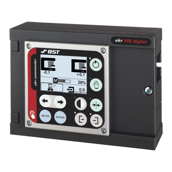
The appearance of the operation display depends on the number of connected wide array edge sensors. Operation with one wide array edge sensor Fig. 11: Operation with one wide array edge sensor (connected as Sensor 1) 28/39 ekr 500 digital Unit Touch – Application with Wide Array Edge Sensors... - Page 29 Fig. 12: Operation with one wide array edge sensor (connected as Sensor 2) Operation with two wide array edge sensors Fig. 13: Operation with two wide array edge sensors ekr 500 digital Unit Touch – Application with Wide Array Edge Sensors 29/39...
-
Page 30: Symbol Meanings
The numeric value indicates the current position of the right web edge in the sensor measuring range. The displayed ③ value is based on the center of the sensor measuring range (position 0). 30/39 ekr 500 digital Unit Touch – Application with Wide Array Edge Sensors... - Page 31 Edge 1 Edge 2 Measuring range (e.g. 162 mm) Edge 1 Edge 2 Measuring range (e.g. 162 mm) Edge 1 Edge 2 Measuring range (e.g. 162 mm) ekr 500 digital Unit Touch – Application with Wide Array Edge Sensors 31/39...
-
Page 32: Display With Loss Of The Web Edge
(material within the sensor measuring range). After recording the signal levels the microprocessor uses the two values to calculate the opacity of the material. 32/39 ekr 500 digital Unit Touch – Application with Wide Array Edge Sensors... -
Page 33: Performing The Material Setup
(Sensor 1 here). 6. Completely clear the selected sensor’s scanning area (no material in the sensor scanning area). 7. Press the > button. ekr 500 digital Unit Touch – Application with Wide Array Edge Sensors 33/39... - Page 34 The bar indicator shows the dark value measured. 11. Press the button. The dark value will be saved. The material setup for the selected sensor is completed. The setup menu is displayed. 34/39 ekr 500 digital Unit Touch – Application with Wide Array Edge Sensors...
-
Page 35: Maintenance And Cleaning
Never use cleaning agents containing solvents, not even with ► intensive soiling, unless the respective cleaning agent is explicitly listed in the instructions. Follow the cleaning instructions. ► ekr 500 digital Unit Touch – Application with Wide Array Edge Sensors 35/39... -
Page 36: 10.2 Maintenance Table
Clean carefully using a dry, clean and soft cloth (e.g. glasses ► wipe). Use a commercially available liquid cleaner in event of intensive ► soiling. Perform the material setup after cleaning. ► 36/39 ekr 500 digital Unit Touch – Application with Wide Array Edge Sensors... -
Page 37: Troubleshooting
The web edge to be scanned is located outside the Correct the position of the wide array edge ► measuring range of the wide array edge sensor. sensor across the web running direction. ekr 500 digital Unit Touch – Application with Wide Array Edge Sensors 37/39... -
Page 38: Accessories And Spare Parts
Cable extension 2 m 131 994 Cable extension 5 m Connection of wide array edge sensors (CAN bus) 131 995 Cable extension 10 m 168 176 Spiral cable 0.5 m / 2 m 38/39 ekr 500 digital Unit Touch – Application with Wide Array Edge Sensors... -
Page 39: Index
Function ............ 32 Types.............. 10 performing ............. 33 Operating manual Distribution ............ 5 Latest version........... 7 Storage............. 5 Operation display Display of the edge position ...... 31 ekr 500 digital Unit Touch – Application with Wide Array Edge Sensors 39/39...
Need help?
Do you have a question about the ekr 500 digital Unit Touch and is the answer not in the manual?
Questions and answers