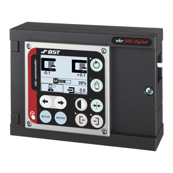
Sign In
Upload
Manuals
Brands
BST Manuals
Controller
ekr 500
BST ekr 500 Manuals
Manuals and User Guides for BST ekr 500. We have
6
BST ekr 500 manuals available for free PDF download: Operating Manual, Installation And Commissioning Manual, Translation Of The Original Manual, Installation And Operating Manual
BST ekr 500 Installation And Commissioning Manual (162 pages)
Unit Touch
Brand:
BST
| Category:
Control Unit
| Size: 6.16 MB
Table of Contents
Table of Contents
3
About this Document
7
What You Need to Know
7
Target Group
7
Storage and Distribution
7
Meanings of the Safety Instructions and Symbols
7
Safety Instructions
7
Symbols
8
Operation Using Keys
8
More Detailed Information
9
About Safety
10
Intended Use
10
Non-Intended Use
11
Non-Intended Infringement of Guidelines
11
Non-Intended Operation
11
Non-Intended Modification of Electronic Data
12
Safety Instructions
13
General Safety Instructions
13
Qualification of the Personnel
15
Duties of the Operating Company and Personnel
16
Duties of the Operating Company
16
Duties of the Personnel
17
Conduct in the Event of Danger and Accidents
17
Personal Protective Equipment
18
Guarantee and Liability
18
Disclaimer
18
Exceptions to the Disclaimer
19
License and Liability for Software Supplied
19
Design and Function
20
Design
20
Controller
20
Control Panel
20
Function
21
Message Output "System OK
22
Connectable Components
23
Designation of the Sensors
24
Edge Sensors (Sensor 1/2)
24
Line, Contrast and Object Sensor (Sensor 3)
25
CCD Cameras (Sensor 1/2)
26
Accessories
27
Nameplates
27
Technical Specifications
28
Controller
28
Ambient Conditions
28
Protection Category
28
Power Supply
29
Analogue Inputs
29
Digital Inputs / Outputs
30
Output Motor Output Stage
30
Message Output "System OK
31
Bus Interface
31
Weight and Dimensions
32
Ekr Commander Control Panel
33
Ambient Conditions
33
Protection Category
33
Power Pack
34
Sensors
35
Edge Sensors
35
Line and Contrast Sensor CLS Pro 600
37
Object Sensor CLS CAM 100
38
CCD Cameras
38
Sensor Positioner
38
Electric Motor Powered Actuators
39
Rohs Conformity
41
Transport, Delivery and Storage
42
Transport
42
Scope of Delivery
43
Unpacking the Delivery
43
Storage
43
Installation
44
Safety Instructions
44
Selecting the Installation Location
45
Installing the Controller
46
Installation Positions
46
Securing Hole Template
47
Space Needed to Open the Housing Cover
47
Installing the Controller
48
Turning the Control Panel
49
Installing the Control Panel
50
Attachment Alternatives
50
Cable Extension
50
Wall Mounting
50
Console Installation
50
Magnet Attachment
50
Electrical Connection
58
Safety Instructions
58
Cable Routing
59
Connecting the Cables
60
EMC Suitable Wiring
61
Ensuring Equipotential Bonding
62
Connections on the Controller
63
Terminal Strips
64
Terminal Assignment
65
Overview
65
Terminal Strip X1 - Sensor 1/2 (Analogue Connection)
66
Terminal Strip X6 - Power Supply
66
Terminal Strip X7 - Actuator, OMG 4
67
Terminal Strip X8 - Sensor 1/2 (CAN Bus)
68
Terminal Strip X9 - Ekr Commander Control Panel, Sensor 3, Drive Module 160
68
Terminal Strip X10 - Controller Interlock, OMG 4, OMG 8, CK 37, EFE 1
69
Terminal Strip X11 - Message Output "System OK
69
Terminal Strip X12 - CAN Bus 4
69
Terminal Strip X14 - Digital Inputs 1
70
Terminal Strip X15 - Digital Inputs 7
70
Plug Connection
71
X60 - Actuator Connection EMS 17/18/21/22
71
X70 - Power Supply
72
X100
73
Commissioning
74
Safety Instructions
74
Requirements
75
Setting the DIL Switches of the Controller
76
DIL Switch Overview
76
Using the DIL Switch
77
Setting DIL Switch S4
78
Setting DIL Switch S5
79
Setting DIL Switch S6
80
Setting DIL Switch S7
80
Setting the DIL Switches of the Control Panel
81
Setting the Jumper
82
Checking the Device Addresses
83
Controller Device Address
83
Control Panel Device Address
84
Setting the Terminating Resistors
85
Terminating Resistor of the Controller
85
Terminating Resistor of the Control Panel
87
Calling up the Setup Menu
89
Setting the Dimension Unit
92
Setting the Motor Rotation Direction
93
Commissioning the Actuator Without Position Feedback
94
Setting the Guiding Direction for Center Positioning
94
Setting the Gain of the Servo Center Transducer
95
Commissioning the Actuator with Position Feedback
97
Setting the Guiding Direction for Center Positioning
97
Setting Stroke Limitation and Servo-Center Position
98
Activating the Normalized Display of the Actuator Position
101
Activating Position Control
104
Setting the Guiding Direction
105
Guiding Direction for Web Edge Guiding and Web Center-Line Guiding (Sensor 1/2)
105
Guiding Direction for Line / Contrast / Feature Guiding (Sensor 3)
106
Performing the Material Setup
106
Adjusting the Controller Gain
107
Commissioning the CCD Camera
109
CCD Camera Calibration
109
Material Thickness Compensation
109
Setting the Material Thickness (after Changing the Material)
116
Entering the Position Offsets
117
Commissioning the Sensor Positioner
119
Calling up the Setting Menu
119
Overview Setting Menu
120
Activating Retract Mode
121
Activating Automatic Setpoint Acceptance
122
Setting Automatic Sensor Tracking
123
Activating Automatic Edge Sensor Standardization
124
Entering the Position Offset for the Sensor Slides
125
Commissioning the Positioning Unit
127
Utilization
127
Calling up the Setting Menu
128
Overview Setting Menu
128
Reversing the Operating Direction of the Arrow Keys
129
Entering the Position Offset for the Sensor Slides
131
Commissioning the Electronic Remote Precision Adjustment (Optional)
133
Efe 1
133
Efe 1000
134
Remote Control (Digital Inputs / Outputs)
135
Safety Information
135
Digital Inputs / Outputs
135
Digital Inputs
135
Digital Outputs
135
Truth Tables
136
Digital Inputs / Outputs Configuration
137
Remote Control with External Control Keyboard Ekr Commander
150
Service Leds
151
Status Display of Remote Control Inputs
152
Status Display of Digital Outputs
152
Display of CAN Bus Status
153
Display of Device Status
153
Status Display of Message Output "System OK
153
Status Display of Power Supply
153
Status Display of Controller Interlock
153
Accessories and Spare Parts
154
Order Address
154
Accessories
154
Customer Services
155
Connection Diagram
156
Application with Edge Sensors
156
Application with CCD Cameras
157
Application with CCD CAM 100
157
Application with Ccdpro 30000/5000
158
Application with Sensor Positioner FVG POS 100
158
Index
159
Advertisement
BST ekr 500 Operating Manual (163 pages)
Unit Touch
Brand:
BST
| Category:
Control Unit
| Size: 5.51 MB
Table of Contents
Table of Contents
3
About this Document
6
What You Need to Know
6
Target Group
6
Storage and Distribution
6
Meanings of the Safety Instructions and Symbols
6
Safety Instructions
6
Symbols
7
Operation Using Keys
7
More Detailed Information
8
About Safety
9
Intended Use
9
Non-Intended Use
10
Non-Intended Infringement of Guidelines
10
Non-Intended Operation
10
Non-Intended Modification of Electronic Data
11
Safety Instructions
12
General Safety Instructions
12
Qualification of the Personnel
14
Duties of the Operating Company and Personnel
15
Duties of the Operating Company
15
Duties of the Personnel
16
Conduct in the Event of Danger and Accidents
16
Personal Protective Equipment
17
Guarantee and Liability
17
Disclaimer
17
Exceptions to the Disclaimer
18
License and Liability for Software Supplied
18
Design and Function
19
Design
19
Controller
19
Control Panel
19
Function
20
Guiding Modes
21
Special Guiding and Monitoring Functions
21
Watchdog
21
Overlaid Web Edge/Web Center-Line Guiding with CLS CAM 100 Object Sensor
22
Speed Dependent Guiding
22
Oscillation
22
Speed-Dependent Oscillation
22
Master-Slave Guiding
22
Tear-Off Detection
23
Web Width Measurement
23
Line Width Measurement
23
Motorized Sensor Positioning
24
Sensor Positioner
24
Positioning Unit
24
Control and Display Elements
25
Touchscreen Display
25
Keys
25
Designation of the Sensors
26
Edge Sensors (Sensor 1/2)
26
Line, Contrast and Object Sensor (Sensor 3)
27
CCD Cameras (Sensor 1/2)
28
Nameplates
29
Technical Specifications
30
Operation
31
Safety Instructions
31
Ekr Commander Control Panel
31
Touchscreen Operation
33
Switching Functions on / off
33
Editing Numerical Values
33
Access to the Online Documentation
35
Operation Display
35
Overview
35
Edge Sensors Operation Display (Sensor 1/2)
42
CLS Pro 600 Line and Contrast Sensor Operation Display (Sensor 3)
43
CLS CAM 100 Object Sensor Operation Display (Sensor 3)
45
CCD Cameras Operation Display
47
Actuator Operation Display
51
Configurable Displays and Setting Menus
52
Performing the Material Setup
54
Overview
54
Activating the Material Setup
57
Cancelling Material Setup
58
Automatic Material Setup
58
Manual Material Setup
59
Selecting the Operating Mode for the IR 2011/40 Edge Sensor
60
Function
60
Requirements
60
IR 2011/40 Operating Modes
61
Operating Mode Selection
62
Selecting the Guiding Mode
63
Selecting the Operating Mode
64
Manual Mode
64
Automatic
65
Center Positioning
65
Setting the Guiding Setpoint
66
Adjusting the Guiding Setpoint with the Arrow Keys
69
Adjusting the Guiding Setpoint with the Setting Menu
70
Accepting Current Position of a Web Edge as Guiding Setpoint
71
Saving and Loading the Guiding Setpoint
73
Entering an Offset Value for the Guiding Setpoint
75
Optimizing the Controller Gain
77
Adjusting the Controller Gain with the Arrow Keys
78
Adjusting the Controller Gain Via the Touchscreen
78
Special Guiding and Monitoring Functions
79
Watchdog
79
Overlaid Web Edge/Web Center-Line Guiding with CLS CAM 100 Object Sensor
82
Speed-Dependent Guiding
85
Master-Slave Guiding
87
Tear-Off Detection
89
Oscillation
91
Speed-Dependent Oscillation
91
Web Width Measurement
100
Line Width Measurement
108
Sensor Positioner
110
Utilization
110
Operation Display
111
Operation
112
Positioning Unit
115
Utilization
115
Requirements
116
Operation
116
Calling up the Setup Menu
120
Switching the Configurable Displays and Setting Menus On/Off
123
Service Displays
124
Displaying System Information
125
Displaying System Components
126
Displaying Switch Positions
128
Displaying a Link to the Company Website
129
Displaying Service QR Code
130
Fault Displays
132
Limit Switch Active
132
Actuator Blocked (Motor Overcurrent)
132
Supply Voltage Outside the Permissible Range
133
Motor Control Timeout
133
Controller Interlock Active
134
Keyboard Interlock Active
135
Setup Lock Active
135
Bus Connection Fault
136
Edge Sensor Malfunction
136
Loss of the Line / Contrast Transition (Sensor CLS Pro 600)
137
Loss of the Guiding Criterion (Object Sensor CLS CAM 100)
137
Loss of the Web Edge (CCD Camera)
138
External Motor Output Stage Fault (Drive Module 160)
138
Electronic Remote Precision Adjustment (Option)
139
Efe 1
139
Efe 1000
139
Extended Device Settings
140
Editing the Parameter Value
140
Public Parameters Lists
142
Restoring Factory Default Settings
147
Maintenance and Cleaning
148
Safety Instructions
148
Maintenance Table
149
Maintenance and Cleaning Work
149
Cleaning the Controller Housing
149
Cleaning the Control Panel Housing
149
Cleaning the Edge Sensor Housing
150
Cleaning the Housing of the CLS Pro 600 Line and Contrast Sensor
150
Cleaning the Housing of the CLS CAM 100 Object Sensor
150
Cleaning the Housing of the CCD Camera
150
Cleaning the Electric Motor Powered Actuator Housing
150
Cleaning the Sensor Positioner Housing
151
Troubleshooting
152
Customer Services
158
Shutting down and Disposal
159
Index
160
BST ekr 500 Operating Manual (101 pages)
Web guiding controller with removable control panel
Brand:
BST
| Category:
Controller
| Size: 2.46 MB
Table of Contents
Table of Contents
2
Description
5
Symbols Used in this Manual
5
Warning Signs
5
Using the Keys
5
LED Operating Status Indications
5
General
6
Intended Use
7
System Description
8
System Structure
8
Functional Principle
9
Connectable Components
9
Terms Used
10
Set Position
10
Sensor 1 / Sensor
11
Control Panel
12
Graphical Display
12
Safety Information
14
ESD Protection
16
Emissions
16
Rohs Conformity
16
Technical Data
17
Controller
17
Ambient Conditions
17
Protection Class
17
Power Supply (Terminal Strip X6)
17
Analogue Inputs (Terminal Strip X1, X2, X3)
17
Digital Inputs (Terminal Strip X14)
18
Ouput Motor Output Stage (Terminal Strip X7)
18
Output Fault Relay (Terminal Strip X10)
18
Control Panel Interface (Terminal Strip X8)
19
Weight, Dimensions
19
Control Panel
20
Ambient Conditions
20
Protection Class
20
Power Supply
20
Display
20
Weight, Dimensions
20
Sensors
22
Infrared Sensors
22
Ultrasonic Sensors
22
Electric-Motor-Driven Actuators
23
Power Pack
24
Transport
25
Storage
25
Assembly
26
Installation Site Requirements
26
Assembly of the Controller
27
General
27
Mounting Plan
27
Space Needed to Open the Enclosure Cover
27
Mounting
28
Turning the Control Panel
29
Assembly of the Control Panel
30
General
30
Wall Mounting
31
Control Console Mounting
33
Installation
35
General
35
Fitting the Cable Connections
35
Installation Instructions for EMC-Wiring
36
Overview Processor Board
37
Terminal Assignment
38
Terminal Overview
38
Terminal Assignment
39
Plug Assignments
42
Set DIL Switches
44
DIL Switch S4
44
DIL Switch S5
45
Service Indications
46
Leds "Bus Status
46
Leds "Device Status
46
Leds "Power Supply
47
Leds "Controller Interlock"/ "OK Signal
47
Leds "Remote Control
47
Start-Up
48
Start-Up Actuator
48
General
48
Determine Sense of Motor Rotation
49
Determine Guiding Direction
49
Actuator Without Position Feedback (EMS 5 / 10 / 16)
50
Actuator with Position Feedback
52
(Ems 17, Ems 21, Ems 22)
52
Carry out Material Setup
56
Adjustment of Gain
57
Start-Up Electronic Remote Precision Adjustment (Option)
58
Operation
59
Operation Display
59
Basic Display
59
Special Displays
60
Material Setup
64
General
64
Activate Material Setup
65
Procedure for Web Edge Guiding
66
Procedure for Web Center-Line Guiding
68
Operating Mode Selection
72
Manual Positioning
72
Automatic Guiding
72
Center Positioning
72
Setting the Web Set Point
73
Optimise Gain
75
Display of System Information
76
Electronic Remote Precision Adjustment (Option)
77
Remote Control
78
Default Settings
79
Device Addresses
79
Device Address of the Controller
79
Device Address of the Control Panel
80
Keyboard Bus Terminating Resistors
81
Controller Terminating Resistor
81
Control Panel Terminating Resistor
82
Generating the Default Settings
83
Trouble Shooting
84
Maintenance
88
General
88
Controller
88
Control Panel
88
Sensors
89
Electric-Motor-Driven Actuator
89
Decommissioning
90
Index
91
Connecting Plan
94
Advertisement
BST ekr 500 Operating Manual (45 pages)
Brand:
BST
| Category:
Controller
| Size: 2.13 MB
Table of Contents
Table of Contents
3
About this Document
5
What You Need to Know
5
Target Group
5
Storage and Distribution
5
Meanings of the Safety Instructions and Symbols
6
Safety Instructions
6
Symbols
6
Operation Using Keys
6
More Detailed Information
7
About Safety
8
Intended Use
8
Non-Intended Use
8
Safety Instructions
8
Design and Function
9
Functional Principle
9
Guiding Modes
10
Web Guiding Components Used
11
Web Guiding Controller
11
Guiding Device
11
Sensor Positioners
11
Installation
12
Electrical Connection
13
Safety Instructions
13
Fitting the Cable Connections
14
Required Accessories
14
Wiring Diagrams
14
Connector Assignment
15
Master-Slave Guiding with Two Edge Sensors
15
Terminal Assignment of Terminal Strip X12 (Connection Sensor 4)
16
Commissioning
19
Safety Instructions
19
Requirements
20
Enabling Master-Slave Guiding
21
Performing the Material Setup
21
Commissioning the Sensor Positioners
22
Calling up the Setting Menu
22
Overview Setting Menu
23
Activating Retract Mode
25
Activating Automatic Setpoint Acceptance
26
Setting Automatic Sensor Tracking
27
Activating Automatic Edge Sensor Standardization
28
Entering the Position Offset for the Sensor Slides
29
Operation
31
Safety Instructions
31
Switching on the Master-Slave Guiding
32
Operation Display
34
Performing the Material Setup
35
When Does a Material Setup Have to be Carried out
35
Manual or Automatic Material Setup
35
Generating Bright / Dark Values
35
Activating the Material Setup
36
Automatic Material Setup
36
Manual Material Setup
36
Accessories and Spare Parts
40
Order Address
40
Accessories
40
A Wiring Diagrams
41
A1 Master-Slave Guiding (Web Edge Guiding)
41
Guiding to the Left Web Edge
41
A1.2 Guiding to the Right Web Edge
42
A2 Master-Slave Guiding (Web Edge/Web Center-Line Guiding)
43
Index
44
BST ekr 500 Translation Of The Original Manual (67 pages)
CANopen User Gateway
Brand:
BST
| Category:
Gateway
| Size: 1.34 MB
Table of Contents
Table of Contents
3
About this Document
4
What You Need to Know
4
Target Group
4
Storage and Distribution
4
Meanings of the Safety Instructions and Symbols
5
Safety Instructions
5
Symbols
5
Operation Using Keys
5
More Detailed Information
6
Functional Description
7
Utilisation
7
Canopen Communication Profile
8
Fundamentals
8
Object Dictionary
9
Communication Objects
10
Service Data Objects
11
Process Data Objects
13
Communication Protocol
14
Baud Rate
14
CAN Bus Wiring
14
Commissioning
15
Safety Instructions
15
Connecting the Controller to the External CAN Bus
16
Setting the Terminating Resistor of the Controller
17
Configuring the CAN Bus Interface
18
Configuring the Connector Socket X101 for Networking
18
Activating the Galvanic Separation
19
Setting the Baud Rate
20
Selecting the Communication Protocol
21
Loading the EDS File
23
Protocol 3100
24
Process Data Objects
24
Object Descriptions
24
Service Data Objects
25
Service Data Objects Overview
25
Object Descriptions
29
Examples for the Application of the Service Data Objects
63
Index
66
BST ekr 500 Installation And Operating Manual (39 pages)
Application with Wide Array Edge Sensors
Brand:
BST
| Category:
Controller
| Size: 1.36 MB
Table of Contents
Table of Contents
3
About this Document
5
What You Need to Know
5
Target Group
5
Storage and Distribution
5
Meanings of the Safety Instructions and Symbols
6
Safety Instructions
6
Symbols
6
Operation Using Keys
6
More Detailed Information
7
About Safety
8
Intended Use
8
Non-Intended Use
8
Safety Instructions
8
Design and Function
9
Components
9
Design
9
Wide Array Edge Sensors
10
Properties
10
Sensor Types
10
Measuring Range
11
Indicator LED
12
Guiding Modes
13
Technical Specifications
14
Ultrasonic Wide Array Edge Sensors US SEN 300
14
Infrared Wide Array Edge Sensors IR SEN 400
16
Connection Box
18
Transport, Delivery and Storage
19
Transport
19
Scope of Delivery
19
Unpacking the Delivery
19
Storage
19
Installation
20
Safety Instructions
20
Installing the Wide Array Edge Sensor
20
Selecting the Installation Location
20
Installing the Connection Box
22
Selecting the Installation Location
22
Electrical Connection
23
Safety Instructions
23
Connecting the Wide Array Edge Sensor to the Controller
24
Checking Correct Connection
25
Commissioning
26
Safety Instructions
26
Requirements
27
Safety Instructions
28
Operation Display
28
Symbol Meanings
30
Display with Loss of the Web Edge
32
Performing the Material Setup
32
Function
32
Performing the Material Setup
33
Maintenance and Cleaning
35
10.1 Safety Instructions
35
10.2 Maintenance Table
36
10.3 Maintenance and Cleaning Work
36
10.3.1 Cleaning the Wide Array Edge Sensor Housing
36
Troubleshooting
37
Accessories and Spare Parts
38
12.1 Order Address
38
12.2 Accessories
38
Index
39
Advertisement
Related Products
BST ekr 500 Plus
BST eltromat EKR 1500
BST EcoGuide
BST ECOGuide MD.464.EN.05
BST ekr CON 100
BST ekr CON 600
BST ekr CON 600 net
BST Categories
Speakers
Speaker System
Amplifier
Controller
Security Sensors
More BST Manuals
Login
Sign In
OR
Sign in with Facebook
Sign in with Google
Upload manual
Upload from disk
Upload from URL