BST ekr 500 digital Unit Touch Operating Manual
Hide thumbs
Also See for ekr 500 digital Unit Touch:
- Installation and operating manual (204 pages) ,
- Operating manual (163 pages) ,
- Installation and commissioning manual (162 pages)

Related Manuals for BST ekr 500 digital Unit Touch


Summary of Contents for BST ekr 500 digital Unit Touch
- Page 1 Web Guiding System Operating Manual ekr 500 digital Unit Touch Master-Slave Guiding with Sensor Positioner MD.535.EN.02 Translation of the Original Manual...
- Page 2 BST GmbH Remusweg 1 D-33729 Bielefeld Tel.: +49 (0) 521 400 70 0 Fax: +49 (0) 5206 999 999 E-Mail: info@bst.group Internet: www.bst.group This documentation is protected by copyright. The translation as well as reproduction and distribution in any form is forbidden without the approval...
-
Page 3: Table Of Contents
Performing the Material Setup ................... 35 7.4.1 When does a material setup have to be carried out?.......... 35 7.4.2 Manual or automatic material setup? ................ 35 7.4.3 Generating bright / dark values .................. 35 ekr 500 digital Unit Touch – Master-Slave Guiding with Sensor Positioner... - Page 4 Master-Slave Guiding (Web Edge Guiding).............. 41 A1.1 Guiding to the Left Web Edge .................. 41 A1.2 Guiding to the Right Web Edge................... 42 Master-Slave Guiding (Web Edge/Web Center-line Guiding) ........ 43 Index........................ 44 ekr 500 digital Unit Touch – Master-Slave Guiding with Sensor Positioner...
-
Page 5: About This Document
What You Need to Know These instructions describe the special function Master-Slave Guid- ing with Sensor Positioner of the ekr 500 digital Unit Touch web guiding controller. They are a supplement to the operating manual for the ekr 500 digital Unit Touch controller (document number MD.492). -
Page 6: Meanings Of The Safety Instructions And Symbols
Operations using the keys are indicated by the following symbols: Press key ①. ► Press key ① or key ②. ► Press key ① and key ② at the same time. ► 6/45 ekr 500 digital Unit Touch – Master-Slave Guiding with Sensor Positioner... -
Page 7: More Detailed Information
BST.Help. Component Document Document Number Operating manual MD.492 Web guiding controller Installation and ekr 500 digital Unit Touch MD.497 commissioning manual Sensor positioner Operating manual MD.476 FVG POS 100 ekr 500 digital Unit Touch – Master-Slave Guiding with Sensor Positioner 7/45... -
Page 8: About Safety
Intended Use The special function Master-Slave Guiding with Sensor Positioner of the ekr 500 digital Unit Touch web guiding controller is only determined for web guiding. It is used when two webs of material have to be guided together precisely to the web edge or web center-line. -
Page 9: Design And Function
Sensor 3 MASTER web Distance (unguided) web edges Sensor 4 Fig. 1: Master-slave guiding for guiding together two webs of material precisely to the web edge or web center-line ekr 500 digital Unit Touch – Master-Slave Guiding with Sensor Positioner 9/45... -
Page 10: Guiding Modes
Positioner permits the following guiding modes. Guiding to the left web edge Guiding to the right web edge Web center-line guiding SLAVE web SLAVE web SLAVE web MASTER web MASTER web MASTER web 10/45 ekr 500 digital Unit Touch – Master-Slave Guiding with Sensor Positioner... -
Page 11: Web Guiding Components Used
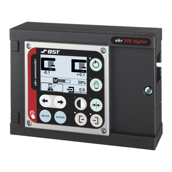
Positioner consists of the components described in the following chapters. 3.3.1 Web Guiding Controller The ekr 500 digital Unit Touch web guiding controller is used to control and operate the Master-Slave Guiding. Requirements The following requirements must be fulfilled for using the Master-... -
Page 12: Installation
Master-Slave Guiding is described in separate documents. Component Document Document Number Web guiding controller Installation and MD.497 ekr 500 digital Unit Touch commissioning manual Sensor positioner Operating manual MD.476 FVG POS 100 12/45 ekr 500 digital Unit Touch – Master-Slave Guiding with Sensor Positioner... -
Page 13: Electrical Connection
Please also read and follow all safety instructions contained in ► the installation and operating manual for the ekr 500 digital Unit Touch controller (document number MD.497). ekr 500 digital Unit Touch – Master-Slave Guiding with Sensor Positioner 13/45... -
Page 14: Fitting The Cable Connections
Fitting the Cable Connections 5.2.1 Required Accessories For connecting the edge sensors to the ekr 500 digital Unit Touch web guiding controller you need optional extension cables. Only original accessory components from BST may be used. Neglecting this information leads to warranty claims being invalid- ated. -
Page 15: Connector Assignment
Electrical Connection Connector Assignment The assignment of the connectors at the ekr 500 digital Unit Touch controller housing depends on the number of edge sensors used for the Master-Slave Guiding. 5.3.1 Master-Slave Guiding with Two Edge Sensors 5.3.1.1 Guiding to the Left Web Edge Fig. 2: Connector assignment on the controller... -
Page 16: Terminal Assignment Of Terminal Strip X12 (Connection Sensor 4)
Sensor 2 SLAVE web X103 Leads to terminal strip X12 in the controller (see Sensor 4 MASTER web X104 Terminal Assignment of Terminal Strip X12 (Connection Sensor 4), page 18). 16/45 ekr 500 digital Unit Touch – Master-Slave Guiding with Sensor Positioner... - Page 17 Sensor 2 X10³ Sensor 3 X100 Leads to terminal strip X12 in the controller (see MASTER web Sensor 4 X10⁴ Terminal Assignment of Terminal Strip X12 (Connection Sensor 4), page 18). ekr 500 digital Unit Touch – Master-Slave Guiding with Sensor Positioner 17/45...
- Page 18 Fig. 5: Processor board of the controller Terminal Assignment X104 Function Wire Colour Note Terminal +24 V⎓ brown Power supply Sensor 4 CAN4-H white CAN 4 high blue Ground CAN 4 CAN4-L black CAN 4 low 18/45 ekr 500 digital Unit Touch – Master-Slave Guiding with Sensor Positioner...
-
Page 19: Commissioning
There is a danger of crushing during the sensor slide movement, in particular when reaching into the hazard zones identified below. Fig. 6: Hazard zones ekr 500 digital Unit Touch – Master-Slave Guiding with Sensor Positioner 19/45... -
Page 20: Requirements
(controller, sensors, actuator) have been made (see Wiring Dia- grams, page 14). The controller is connected to the power supply. ■ All transport locking devices on the guiding device and actuator ■ have been removed. 20/45 ekr 500 digital Unit Touch – Master-Slave Guiding with Sensor Positioner... -
Page 21: Enabling Master-Slave Guiding
Commissioning Enabling Master-Slave Guiding The Master-Slave Guiding is enabled using the DIL switch S6.6 on the processor board of the ekr 500 digital Unit Touch controller. Fig. 7: DIL switch S6 on the processor board of the controller Enabling Master-Slave Guiding NOTICE Damage to the components from working on live parts. -
Page 22: Commissioning The Sensor Positioners
The first page of the setup menu appears in the display. 3. To call up the next page of the setup menu, keep pressing the right arrow button until the desired menu page is shown in the display. 22/45 ekr 500 digital Unit Touch – Master-Slave Guiding with Sensor Positioner... -
Page 23: Overview Setting Menu
SLAVE web has more setting functions. SLAVE Setting Menu MASTER Setting Menu The meaning of the different buttons in the two setting menus can be found in the following table. ekr 500 digital Unit Touch – Master-Slave Guiding with Sensor Positioner 23/45... - Page 24 MASTER* SLAVE Position offset for the Input of the distance of the right sensor slide to & right sensor slide the reference point. MASTER* * Display function only 24/45 ekr 500 digital Unit Touch – Master-Slave Guiding with Sensor Positioner...
-
Page 25: Activating Retract Mode
The button selected is displayed with a blue background. The corresponding retract mode is activated. 2. Press the SETUP key. The settings made are saved. The setup menu is displayed. ekr 500 digital Unit Touch – Master-Slave Guiding with Sensor Positioner 25/45... -
Page 26: Activating Automatic Setpoint Acceptance
To switch the function Automatic setpoint acceptance on / off, ► press the adjacent button. When the function is switched on, the button is displayed with a blue background. 26/45 ekr 500 digital Unit Touch – Master-Slave Guiding with Sensor Positioner... -
Page 27: Setting Automatic Sensor Tracking
2. Enter the desired distance value A (2.5 mm in the example) to define the hysteresis area in the input field. 3. Press the SETUP key. The settings made are saved. The setup menu is displayed. ekr 500 digital Unit Touch – Master-Slave Guiding with Sensor Positioner 27/45... -
Page 28: Activating Automatic Edge Sensor Standardization
Automatic edge sensor standardization is activated. The button is displayed with a blue background. 2. Press the SETUP key. The settings made are saved. The setup menu is displayed. 28/45 ekr 500 digital Unit Touch – Master-Slave Guiding with Sensor Positioner... -
Page 29: Entering The Position Offset For The Sensor Slides
When entering the position offset, it is essential to observe the prefix sign (+/-). ekr 500 digital Unit Touch – Master-Slave Guiding with Sensor Positioner 29/45... - Page 30 (see example 2). 9. Press the SETUP key. The settings made are saved. The setup menu is displayed. 30/45 ekr 500 digital Unit Touch – Master-Slave Guiding with Sensor Positioner...
-
Page 31: Operation
Please also read and follow all safety instructions contained in ► the operating manuals for the ekr 500 digital Unit Touch con- troller (document number MD.492) and for the FVG POS 100 sensor positioner (document number MD.476). ekr 500 digital Unit Touch – Master-Slave Guiding with Sensor Positioner... -
Page 32: Switching On The Master-Slave Guiding
Before setting up / operating, ensure that no other persons are ► in the traversing area of the sensor slides. ›› The ekr 500 digital Unit Touch controller is in Manual operating mode. 1. Select the desired guiding mode (see Guiding Modes, page 10). Guiding to the left web edge... - Page 33 SLAVE web MASTER web MASTER web MASTER web Offset = 0 Offset = 0 Offset = 0 SLAVE web SLAVE web SLAVE web MASTER web MASTER web MASTER web ekr 500 digital Unit Touch – Master-Slave Guiding with Sensor Positioner 33/45...
-
Page 34: Operation Display
Guiding to the Sensor 1 Left web edge left web edge Guiding to the Sensor 2 Right web edge SLAVE web right web edge Sensor 1 Web center-line & Web center-line guiding Sensor 2 34/45 ekr 500 digital Unit Touch – Master-Slave Guiding with Sensor Positioner... -
Page 35: Performing The Material Setup
If using highly transparent material, when covering the measurement window you must ensure that there are no folds in the material in the sensor scanning area. The material must be tensioned. ekr 500 digital Unit Touch – Master-Slave Guiding with Sensor Positioner 35/45... -
Page 36: Activating The Material Setup
Meaning of the buttons Material Web Edge Sensors Button Material Setup Automatic material setup Sensor 1, SLAVE web Sensor 2 Manual material Setup Automatic material setup Sensor 3, MASTER web Sensor 4 Manual material Setup 36/45 ekr 500 digital Unit Touch – Master-Slave Guiding with Sensor Positioner... - Page 37 The dark value measured is displayed. 8. Press the button. The material setup for the selected sensor is completed. The bright / dark values determined are saved. ð The setup menu is displayed. ekr 500 digital Unit Touch – Master-Slave Guiding with Sensor Positioner 37/45...
- Page 38 6. Completely clear the selected sensor's scanning area (no ma- terial in the scanning area). The bright value measured is displayed. 7. Press the button. The bright value will be saved. 38/45 ekr 500 digital Unit Touch – Master-Slave Guiding with Sensor Positioner...
- Page 39 The dark value measured is displayed. Press the button. The dark value will be saved. The material setup for the selected sensor is completed. ð The setup menu is displayed. ekr 500 digital Unit Touch – Master-Slave Guiding with Sensor Positioner 39/45...
-
Page 40: Accessories And Spare Parts
Connecting cable 5 m For connecting the actuators EMS 17/21/22, you require an additional adapter cable (see pos. 8) 118 449 Connecting cable 10 m 154 374 Adapter cable Connection actuator EMS 17/21/22 40/45 ekr 500 digital Unit Touch – Master-Slave Guiding with Sensor Positioner... -
Page 41: A Wiring Diagrams
MASTER web (unguided) SLAVE web Sensor 1 (guided) Sensor Positioner Actuator Guiding device Fig. 14: Wiring diagram for master-slave guiding with two edge sensors (guiding to the left web edge) ekr 500 digital Unit Touch – Master-Slave Guiding with Sensor Positioner 41/45... -
Page 42: A1.2 Guiding To The Right Web Edge
MASTER web (unguided) SLAVE web Sensor 2 (guided) Sensor Positioner Actuator Guiding device Fig. 15: Wiring diagram for master-slave guiding with two edge sensors (guiding to the right web edge) 42/45 ekr 500 digital Unit Touch – Master-Slave Guiding with Sensor Positioner... -
Page 43: A2 Master-Slave Guiding (Web Edge/Web Center-Line Guiding)
MASTER web (unguided) SLAVE web Sensor 1 Sensor 2 (guided) Sensor Positioner Actuator Guiding device Fig. 16: Wiring diagram for master-slave guiding with four edge sensors (web edge/web center-line guiding) ekr 500 digital Unit Touch – Master-Slave Guiding with Sensor Positioner 43/45... -
Page 44: Index
Entering the position offset ...... 29 Required firmware version ...... 11 Setting menu.......... 22, 23 Setting the automatic sensor tracking ... 27 Guiding device .......... 11 Spare parts............ 40 Guiding modes.......... 10 44/45 ekr 500 digital Unit Touch – Master-Slave Guiding with Sensor Positioner... - Page 45 Index Target group ............. 5 Terminal strip X12 Terminal assignment........ 18 intended............ 8 non-intended ........... 8 Web guiding controller Required firmware version ...... 11 Wiring diagram .......... 14 ekr 500 digital Unit Touch – Master-Slave Guiding with Sensor Positioner 45/45...
Need help?
Do you have a question about the ekr 500 digital Unit Touch and is the answer not in the manual?
Questions and answers