Table of Contents
Advertisement
Available languages
Available languages
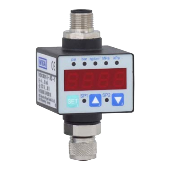
LED attachable indicator, models A-AS-1, WUR-1
LED-Aufsteckanzeige, Typen A-AS-1, WUR-1
Afficheur emboîtable LED, types A-AS-1, WUR-1
Indicador LED acoplable, modelos A-AS-1, WUR-1
LED attachable indicator model A-AS-1
Operating instructions
Betriebsanleitung
Mode d'emploi
Manual de instrucciones
GB
D
F
E
Advertisement
Chapters
Table of Contents

Related Manuals for WIKA A-AS-1


Summary of Contents for WIKA A-AS-1
- Page 1 Operating instructions Betriebsanleitung Mode d'emploi Manual de instrucciones LED attachable indicator, models A-AS-1, WUR-1 LED-Aufsteckanzeige, Typen A-AS-1, WUR-1 Afficheur emboîtable LED, types A-AS-1, WUR-1 Indicador LED acoplable, modelos A-AS-1, WUR-1 LED attachable indicator model A-AS-1...
- Page 2 23 - 42 Mode d‘emploi types A-AS-1, WUR-1 Page 43 - 62 Manual de instrucciones modelos A-AS-1, WUR-1 Página 63 - 82 © 2007 WIKA Alexander Wiegand SE & Co. KG All rights reserved. / Alle Rechte vorbehalten. ® WIKA is a registered trademark in various countries.
-
Page 3: Table Of Contents
7. Maintenance and cleaning 8. Faults 9. Dismounting, return and disposal Appendix 1: EC Declaration of conformity for model A-AS-1 Appendix 2: EC Declaration of conformity for model WUR-1 Declarations of conformity can be found online at www.wika.com. WIKA operating instructions attachable indicator, models A-AS-1, WUR-1... -
Page 4: General Information
Subject to technical modifications. ■ Further information: ■ - Internet address: www.wika.de / www.wika.com - Relevant data sheet: AC 80.09, PE 87.20 - Application consultant: Tel.: (+49) 9372/132-8976 Fax: (+49) 9372/132-8008976 E-mail: info@wika.com WIKA operating instructions attachable indicator, models A-AS-1, WUR-1... -
Page 5: Safety
The technical specifications contained in these operating instructions must be observed. Improper handling or operation of the instrument outside of its technical specifications requires the instrument to be taken out of service immediately and inspected by an authorised WIKA service engineer. WIKA operating instructions attachable indicator, models A-AS-1, WUR-1... - Page 6 Do not use this instrument in safety or emergency-stop devices. Incorrect use of the instrument can result in injury. WIKA operating instructions attachable indicator, models A-AS-1, WUR-1...
- Page 7 Model Pin assignment Output signal Power supply S# Serial no. P# Product no. Explanation of symbols CE, Communauté Européenne Instruments bearing this mark comply with the relevant European directives. WIKA operating instructions attachable indicator, models A-AS-1, WUR-1...
-
Page 8: Specifications
DC 16 ... 30 V for 4 ... 20 mA DC 15 ... 30 V for 0 ... 10 V DC 10 ... 30 V for 0 ... 5 V Influence of supply voltage < 0.1 % of span/10 V WIKA operating instructions attachable indicator, models A-AS-1, WUR-1... - Page 9 Electrical safety Short-circuit resistance to 0V (short-term) ■ Reverse polarity protection to 0V (short-term) ■ Weight 50 g For further specifications see WIKA data sheet AC 80.09, PE 87.20 and the order documentation. WIKA operating instructions attachable indicator, models A-AS-1, WUR-1...
- Page 10 M12 x 1; 5-pin Input Connection socket for bayonet con- nector; 4-pin Output Bayonet connector; Input 4-pin Connection socket for M12 x 1; 4-pin circular connector Output Cable outlet with 3 m length WIKA operating instructions attachable indicator, models A-AS-1, WUR-1...
-
Page 11: Design And Function
Avoid exposure to the following factors: Direct sunlight or proximity to hot objects ■ Mechanical vibration, mechanical shock (putting it down hard) ■ Soot, vapour, dust and corrosive gases ■ Potentially explosive environments, flammable atmospheres ■ WIKA operating instructions attachable indicator, models A-AS-1, WUR-1... -
Page 12: Commissioning, Operation
Power supply 0V, Sig - Signal Sig Connection socket for bayonet connector; 4-pin Power supply U , Sig Power supply U Signal Sig Power supply 0V, Sig - Power supply 0V, Sig - WIKA operating instructions attachable indicator, models A-AS-1, WUR-1... - Page 13 Power supply U , Sig + Power supply U Switching output ground Signal Sig (potential-free) Switching output, out1 Switching output, out1 Power supply 0V, Sig - Power supply 0V Switching output ground, Sig - WIKA operating instructions attachable indicator, models A-AS-1, WUR-1...
- Page 14 After a further 60 seconds without any operation of the keys, the instrument will restart itself. Unsaved changes will be lost. Button 1 Button 2 Button 3 WIKA operating instructions attachable indicator, models A-AS-1, WUR-1...
- Page 15 Confirm the value set using button 1. The display reverts to "di.Hi". ■ By pressing button 1 briefly, the settings are saved. A successful 'Save' is signalled by ■ the display switching off briefly. WIKA operating instructions attachable indicator, models A-AS-1, WUR-1...
- Page 16 Using buttons 2 and 3, select the required switch function for switching output 2. ■ off = always off on = always on no = normally open nc = normally closed Confirm the switching function set using button 1. The display reverts to "out2". ■ WIKA operating instructions attachable indicator, models A-AS-1, WUR-1...
- Page 17 0.1 ... 5.1 V or 0.1 ... 10.1 V. To operate the LED attachable indicator with pressure transmitters with 0 ... 5 V or 0 ... 10 V output signals, an appropri- ate zero point adjustment should be carried out. WIKA operating instructions attachable indicator, models A-AS-1, WUR-1...
-
Page 18: Maintenance And Cleaning
Pressure transmitter defec- once more within the permissible ■ tive/not suitable. limits. Short-circuit in the connec- Check the pressure transmitter ■ ■ tion cabling of the pressure and instrument configuration transmitter WIKA operating instructions attachable indicator, models A-AS-1, WUR-1... -
Page 19: Dismounting, Return And Disposal
WARNING! Absolutely observe the following when shipping the instrument: All instruments delivered to WIKA must be free from any kind of hazardous substances (acids, leachate, solutions, etc.). When returning the instrument, use the original packaging or a suitable transport package. - Page 20 9.3 Disposal Incorrect disposal can put the environment at risk. Dispose of instrument components and packaging materials in an environmentally compatible way and in accordance with the country-specific waste disposal regulations. WIKA operating instructions attachable indicator, models A-AS-1, WUR-1...
-
Page 21: Appendix 1: Ec Declaration Of Conformity For Model A
Appendix 1: EC Declaration of Conformity for model A-AS-1 WIKA operating instructions attachable indicator, models A-AS-1, WUR-1... -
Page 22: Appendix 2: Ec Declaration Of Conformity For Model Wur-1
Appendix 2: EC Declaration of Conformity for model WUR-1 WIKA operating instructions attachable indicator, models A-AS-1, WUR-1... - Page 23 5. Transport, Verpackung und Lagerung 6. Inbetriebnahme, Betrieb 7. Wartung und Reinigung 8. Störungen 9. Demontage, Rücksendung und Entsorgung Anlage 1: EG-Konformitätserklärung Typ A-AS-1 Anlage 2: EG-Konformitätserklärung Typ WUR-1 Konformitätserklärungen finden Sie online unter www.wika.de. WIKA Betriebsanleitung Aufsteckanzeige, Typen A-AS-1, WUR-1...
-
Page 24: Allgemeines
Es gelten die allgemeinen Geschäftsbedingungen in den Verkaufsunterlagen. ■ Technische Änderungen vorbehalten. ■ Weitere Informationen: ■ - Internet-Adresse: www.wika.de / www.wika.com - zugehöriges Datenblatt: AC 80.09, PE 87.20 - Anwendungsberater: Tel.: (+49) 9372/132-8976 Fax: (+49) 9372/132-8008976 E-Mail: info@wika.de WIKA Betriebsanleitung Aufsteckanzeige, Typen A-AS-1, WUR-1... -
Page 25: Sicherheit
Die technischen Spezifikationen in dieser Betriebsanleitung sind einzuhalten. Eine unsachgemäße Handhabung oder ein Betreiben des Gerätes außerhalb der technischen Spezifikationen macht die sofortige Stilllegung und Überprüfung durch einen autorisier- ten WIKA-Servicemitarbeiter erforderlich. WIKA Betriebsanleitung Aufsteckanzeige, Typen A-AS-1, WUR-1... - Page 26 Stoffen, sowie bei Kälteanlagen, Kompressoren etc. müssen über die gesamten allgemeinen Regeln hinaus die einschlägigen Vorschrif- ten beachtet werden. Dieses Gerät nicht in Sicherheits- oder in Not-Aus-Einrichtungen benutzen. Fehlerhafte Anwendungen des Gerätes können zu Verletzungen führen. WIKA Betriebsanleitung Aufsteckanzeige, Typen A-AS-1, WUR-1...
- Page 27 Fremdgeräten (z. B. Verbindung GND mit Schutzerde) zu nicht erlaubten Spannungspotentialen führen. 2.4 Beschilderung/Sicherheitskennzeichnungen Typenschild Symbolerklärung siehe unten Anschlussbelegung Ausgangssignal Hilfsenergie S# Serien-Nr. P# Erzeugnis-Nr. Symbolerklärung CE, Communauté Européenne Geräte mit dieser Kennzeichnung stimmen überein mit den zutreffenden europäischen Richtlinien. WIKA Betriebsanleitung Aufsteckanzeige, Typen A-AS-1, WUR-1...
-
Page 28: Technische Daten
DC 16 ... 30 V bei 4 ... 20 mA DC 15 ... 30 V bei 0 ... 10 V DC 10 ... 30 V bei 0 ... 5 V Einfluss der Hilfsenergie < 0,1 % der Spanne/10 V WIKA Betriebsanleitung Aufsteckanzeige, Typen A-AS-1, WUR-1... - Page 29 5 g bei 10 ... 2.000 Hz nach IEC 60068-2-6 (Vibration bei Resonanz) Elektrische Sicherheit Kurzschlussfestigkeit gegen 0V (kurzzeitig) ■ Verpolschutz gegen 0V (kurzzeitig) ■ Gewicht 50 g Weitere technische Daten siehe WIKA-Datenblatt AC 80.09, PE 87.20 und Bestellunterlagen. WIKA Betriebsanleitung Aufsteckanzeige, Typen A-AS-1, WUR-1...
- Page 30 M12 x 1; 4-polig Bajonettstecker; 4-polig Top-View-Ausführung Ausgang Rundstecker M12 x 1; 5-polig Eingang Anschlussbuchse für Bajonettstecker; 4-polig Ausgang Eingang Bajonettstecker; Anschlussbuchse 4-polig für Rundstecker M12 x 1; 4-polig Ausgang Kabelausgang mit 3 m Länge WIKA Betriebsanleitung Aufsteckanzeige, Typen A-AS-1, WUR-1...
-
Page 31: Aufbau Und Funktion
Lagertemperatur: -30 ... +85 °C Folgende Einflüsse vermeiden: Direktes Sonnenlicht oder Nähe zu heißen Gegenständen ■ Mechanische Vibration, mechanischer Schock (hartes Aufstellen) ■ Ruß, Dampf, Staub und korrosive Gase ■ Explosionsgefährdete Umgebung, entzündliche Atmosphären ■ WIKA Betriebsanleitung Aufsteckanzeige, Typen A-AS-1, WUR-1... -
Page 32: Inbetriebnahme, Betrieb
, Sig + Hilfsenergie U Hilfsenergie 0V, Sig - Hilfsenergie 0V, Sig - Signal Sig+ Anschlussbuchse für Bajonettstecker, 4-polig Hilfsenergie U , Sig Hilfsenergie U Signal Sig Hilfsenergie 0V, Sig - Hilfsenergie 0V, Sig - WIKA Betriebsanleitung Aufsteckanzeige, Typen A-AS-1, WUR-1... - Page 33 Schaltausgang out1 Schaltausgang out2 orange Schaltausgang out2 Bajonettstecker, 4-polig Hilfsenergie U , Sig Hilfsenergie U Schaltausgang Masse Signal Sig (potentialfrei) Schaltausgang out1 Schaltausgang out1 Hilfsenergie 0V, Sig - Hilfsenergie 0V Schaltausgang Masse, Sig - WIKA Betriebsanleitung Aufsteckanzeige, Typen A-AS-1, WUR-1...
- Page 34 10 Sekunden keine Taste betätigt, wechselt das Gerät automatisch in die übergeordne- te Menüebene. Nach weiteren 60 Sekun- den ohne Tastenbetätigung führt das Gerät einen Neustart durch. Nichtgespeicherte Änderungen gehen verloren. Taste 1 Taste 2 Taste 3 WIKA Betriebsanleitung Aufsteckanzeige, Typen A-AS-1, WUR-1...
- Page 35 Den eingestellten Wert mit Taste 1 bestätigen. Die Anzeige springt zurück zu "di.Hi". ■ Durch kurze Betätigung der Taste 1, werden die Einstellungen gespeichert. Ein erfolg- ■ reicher Speichervorgang wird durch kurzzeitiges Erlöschen der Anzeige signalisiert. WIKA Betriebsanleitung Aufsteckanzeige, Typen A-AS-1, WUR-1...
- Page 36 Über die Tasten 2 und 3 den gewünschten Schaltpunkt für den Schaltausgang 2 ■ auswählen. Die eingestellte Einheit mit Taste 1 bestätigen. Die Anzeige springt zurück zu „SP2“. ■ Die Taste 1 kurz drücken um in den Menüpunkt „out2“ zu gelangen. ■ WIKA Betriebsanleitung Aufsteckanzeige, Typen A-AS-1, WUR-1...
- Page 37 Über die Tasten 2 und 3 die gewünschten Nullpunktverschiebung einstellen (zulässi- ■ ger Bereich ±10 % des Anzeigebereiches). Die eingestellte Nullpunktverschiebung mit Taste 1 bestätigen. Die Anzeige springt ■ zurück zu "OFFS". Die Taste 1 kurz drücken damit der Anzeigewert wieder dargestellt wird. ■ WIKA Betriebsanleitung Aufsteckanzeige, Typen A-AS-1, WUR-1...
-
Page 38: Wartung Und Reinigung
Err.1 ■ ■ Messbereich Druckmessumformer gesetzt, sobald das Eingangs- ■ überschritten defekt/ungeeignet signal wieder innerhalb der Kurzschluss der zugelassenen Grenzen liegt. ■ Anschlussleitung des Druckmessumformer und Geräte- ■ Druckmessumformers konfiguration überprüfen (z. B. Eingangssignal). WIKA Betriebsanleitung Aufsteckanzeige, Typen A-AS-1, WUR-1... -
Page 39: Demontage, Rücksendung Und Entsorgung
WARNUNG! Messstoffreste in ausgebauten Geräten können zur Gefährdung von Perso- nen, Umwelt und Einrichtung führen. Ausreichende Vorsichtsmaßnahmen ergreifen. 9.1 Demontage Die LED-Aufsteckanzeige von der Hilfsenergie trennen. Bei Steckverbindern die Verschraubung lösen und auseinander ziehen. WIKA Betriebsanleitung Aufsteckanzeige, Typen A-AS-1, WUR-1... - Page 40 9. Demontage, Rücksendung und Entsorgung 9.2 Rücksendung WARNUNG! Beim Versand des Gerätes unbedingt beachten: Alle an WIKA gelieferten Geräte müssen frei von Gefahrstoffen (Säuren, Laugen, Lösungen, etc.) sein. Zur Rücksendung des Gerätes die Originalverpackung oder eine geeignete Transport- verpackung verwenden.
-
Page 41: Anlage 1: Eg-Konformitätserklärung Typ A
Anlage 1: Konformitätserklärung Typ A-AS-1 WIKA Betriebsanleitung Aufsteckanzeige, Typen A-AS-1, WUR-1... -
Page 42: Anlage 2: Eg-Konformitätserklärung Typ Wur-1
Anlage 2: Konformitätserklärung Typ WUR-1 WIKA Betriebsanleitung Aufsteckanzeige, Typen A-AS-1, WUR-1... - Page 43 7. Entretien et nettoyage 8. Dysfonctionnements 9. Démontage, retour et mise au rebut Annexe 1 : Déclaration de conformité CE pour le type A-AS-1 61 Annexe 2 : Déclaration de conformité CE pour le type WUR-1 Déclarations de conformité disponibles sur www.wika.fr.
-
Page 44: Généralités
- Consulter notre site Internet : www.wika.fr - Fiche technique correspondante : AC 80.09, PE 87.20 - Conseiller applications : Tél. : (+33) 1 343084-84 Fax : (+33) 1 343084-94 E-Mail : info@wika.fr WIKA mode d'emploi afficheur emboîtable LED, types A-AS-1, WUR-1... -
Page 45: Sécurité
En cas d’utilisation inadéquate ou de fonctionnement de l’instrument en dehors des spécifications techniques, un arrêt et contrôle doivent être immédiatement effectués par un collaborateur autorisé du service de WIKA. WIKA mode d'emploi afficheur emboîtable LED, types A-AS-1, WUR-1... - Page 46 être observées en plus de l’ensemble des règles générales. Ne pas utiliser cet instrument dans des dispositifs de sécurité ou d’arrêt d’urgence. Une utilisation incorrecte de l’instrument peut occasionner des blessures. WIKA mode d'emploi afficheur emboîtable LED, types A-AS-1, WUR-1...
- Page 47 Configuration du raccordement Signal de sortie Alimentation S# N° Série P# N° Produit Explication des symboles CE, Communauté européenne Les instruments avec ce marquage sont conformes aux directives européennes pertinentes. WIKA mode d'emploi afficheur emboîtable LED, types A-AS-1, WUR-1...
-
Page 48: Spécifications
16 ... 30 VDC pour 4 ... 20 mA 15 ... 30 VDC pour 0 ... 10 V 10 ... 30 VDC pour 0 ... 5 V Influence de la tension < 0,1 % de l'échelle/10 V d'alimentation WIKA mode d'emploi afficheur emboîtable LED, types A-AS-1, WUR-1... - Page 49 Protection contre l'inversion de polarité à 0V (temporaire) ■ Poids 50 g Pour de plus amples spécifications, voir la fiche technique WIKA AC 80.09, PE 87.20 et la documentation de la commande. WIKA mode d'emploi afficheur emboîtable LED, types A-AS-1, WUR-1...
- Page 50 4 plots Sortie Connecteur à Entrée baïonnette ; 4 plots Prise de raccordement pour connecteur circulaire M12 x 1 ; 4 plots Sortie sortie de câble d'une longueur de 3 m WIKA mode d'emploi afficheur emboîtable LED, types A-AS-1, WUR-1...
-
Page 51: Conception Et Fonction
1. Emballer l’instrument dans une feuille de plastique antistatique. 2. Placer l’instrument avec le matériau isolant dans l’emballage. 3. En cas d’entreposage long (plus de 30 jours), mettre également un sachet absorbeur d’humidité dans l’emballage. WIKA mode d'emploi afficheur emboîtable LED, types A-AS-1, WUR-1... -
Page 52: Mise En Service, Exploitation
Alimentation 0V, Sig - Signal Sig Prise de raccordement pour connecteur à baïonnette ; 4 plots Alimentation U , Sig Alimentation U Signal Sig Alimentation 0V, Sig - Alimentation 0V, Sig - WIKA mode d'emploi afficheur emboîtable LED, types A-AS-1, WUR-1... - Page 53 Terre de la sortie de commutation Signal Sig (sans potentiel) Sortie de commutation, out1 Sortie de commutation, out1 Alimentation 0V, Sig - Alimentation 0V Terre de la sortie de commutation, Sig - WIKA mode d'emploi afficheur emboîtable LED, types A-AS-1, WUR-1...
- Page 54 1 supérieur du menu. Si aucune touche n'est appuyée pendant 60 secondes de plus, l'instrument redémarrera lui-même. Les modifications non enregistrées seront perdues. Touche 1 Touche 2 Touche 3 WIKA mode d'emploi afficheur emboîtable LED, types A-AS-1, WUR-1...
- Page 55 Confirmer la valeur définie à l'aide de la touche 1. L'affichage revient sur "di.Hi". ■ En appuyant brièvement sur la touche 1, les paramètres sont enregistrés. Un enregis- ■ trement réussi est signalé par une désactivation rapide de l'affichage. WIKA mode d'emploi afficheur emboîtable LED, types A-AS-1, WUR-1...
- Page 56 Sélectionner le point de commutation requis pour la sortie de commutation 2 à l’aide des ■ touches 2 et 3. Confirmer l’unité définie à l’aide de la touche 1. L’affichage revient sur "SP2". ■ WIKA mode d'emploi afficheur emboîtable LED, types A-AS-1, WUR-1...
- Page 57 Confirmer le décalage au point zéro à l’aide de la touche 1. L’affichage revient sur ■ "OFFS". En appuyant brièvement sur la touche 1, la valeur d’affichage sera à nouveau ■ présentée. WIKA mode d'emploi afficheur emboîtable LED, types A-AS-1, WUR-1...
-
Page 58: Entretien Et Nettoyage
à nouveau dans les limites Court-circuit dans le câblage admissibles. ■ de raccordement du trans- Vérifier le transmetteur de pression ■ metteur de pression et la configuration de l'instrument (par exemple, le signal d'entrée). WIKA mode d'emploi afficheur emboîtable LED, types A-AS-1, WUR-1... -
Page 59: Démontage, Retour Et Mise Au Rebut
Prendre des mesures de sécurité suffisantes. 9.1 Démontage Débrancher l’afficheur emboîtable LED de l’alimentation électrique. Pour les prises, retirer le raccordement à fil en tirant dessus. WIKA mode d'emploi afficheur emboîtable LED, types A-AS-1, WUR-1... - Page 60 Il faut absolument observer les consignes suivantes lors de l’expédi- tion de l’instrument : Tous les instruments envoyés à WIKA doivent être exempts de toute substance dangereuse (acides, lixiviats, solutions, etc.). Pour retourner l’instrument, utiliser l’emballage d’origine ou un emballage adapté pour le transport.
-
Page 61: Annexe 1 : Déclaration De Conformité Ce Pour Le Type A
Annexe 1 : Déclaration de conformité CE pour le type A-AS-1 WIKA mode d'emploi afficheur emboîtable LED, types A-AS-1, WUR-1... -
Page 62: Annexe 2 : Déclaration De Conformité Ce Pour Le Type Wur-1
Annexe 2 : Déclaration de conformité CE pour le type WUR-1 WIKA mode d'emploi afficheur emboîtable LED, types A-AS-1, WUR-1... - Page 63 7. Mantenimiento y limpieza 8. Error 9. Desmontaje, devolución y eliminación de residuos Anexo 1: Declaración CE de conformidad modelo A-AS-1 Anexo 2: Declaración CE de conformidad modelo WUR-1 Declaraciones de conformidad puede encontrar en www.wika.es. WIKA manual de instrucciones indicador LED acoplable modelo A-AI-1...
-
Page 64: Información General
Para obtener más informaciones consultar: ■ - Página web: www.wika.es / www.wika.com - Hoja técnica correspondiente: AC 80.09, PE 87.20 - Servicio técnico: Tel.: (+34) 933 938-630 Fax: (+34) 933 938-666 E-Mail: info@wika.es WIKA manual de instrucciones indicador LED acoplable modelo A-AI-1... -
Page 65: Seguridad
Cumplir las especificaciones técnicas de este manual de instrucciones. Un manejo no apropiado o una utilización del instrumento no conforme a las especificaciones técnicas requiere la inmediata puesta fuera de servicio y la comprobación por parte de un técnico autorizado por WIKA. WIKA manual de instrucciones indicador LED acoplable modelo A-AI-1... - Page 66 No utilizar este instrumento en sistemas de seguridad o dispositivos de parada de emergencia. Una utilización incorrecta del instrumento puede causar lesiones. WIKA manual de instrucciones indicador LED acoplable modelo A-AI-1...
- Page 67 Detalles del conexio- nado Señal de salida Alimentación auxiliar S# nº de serie P# nº de artículo Explicación de símbolos CE, Communauté Européenne Los instrumentos con este marcaje cumplen las directivas europeas aplicables. WIKA manual de instrucciones indicador LED acoplable modelo A-AI-1...
-
Page 68: Datos Técnicos
DC 15 ... 30 V a 0 ... 10 V DC 10 ... 30 V a 0 ... 5 V Influencia de la alimentación < 0,1 % del span/10 V auxiliar WIKA manual de instrucciones indicador LED acoplable modelo A-AI-1... - Page 69 Protección contra polaridad inversa contra 0V (brevemente) ■ Peso 50 g Para más datos técnicos véase la hoja técnica de WIKA AC 80.09, PE 87.20 y la documenta- ción de pedido. WIKA manual de instrucciones indicador LED acoplable modelo A-AI-1...
- Page 70 Hembrilla para conector tipo bayo- neta; 4 polos Salida Entrada Conector tipo Hembrilla para bayoneta; 4-pin conector circular M12 x 1; 4-pin Salida Salida de cable con una longitud de 3 m WIKA manual de instrucciones indicador LED acoplable modelo A-AI-1...
-
Page 71: Diseño Y Función
Evitar lo siguiente: Luz solar directa o proximidad a objetos calientes ■ Vibración mecánica, impacto mecánico (colocación brusca) ■ Hollín, vapor, polvo y gases corrosivos ■ Entorno potencialmente explosivo, atmósferas inflamables ■ WIKA manual de instrucciones indicador LED acoplable modelo A-AI-1... -
Page 72: Puesta En Servicio, Funcionamiento
Alimentación auxiliar 0V, Sig - Señal Sig Hembrilla para conector tipo bayoneta; 4-pin Alimentación auxiliar U , Sig Alimentación auxiliar U Señal Sig Alimentación auxiliar 0V, Sig - Alimentación auxiliar 0V, Sig - WIKA manual de instrucciones indicador LED acoplable modelo A-AI-1... - Page 73 Salida de conexión masa (libre Señal Sig de potencial) Salida de conexión out1 Salida de conexión out1 Alimentación auxiliar 0V, Sig - Alimentación auxiliar 0V Salida de conexión masa, Sig - WIKA manual de instrucciones indicador LED acoplable modelo A-AI-1...
- Page 74 Al cabo de otros 60 segundos de inactividad, se efectúa un reinicio. Los cambios no guardados se pierden. Tecla 1 Tecla 2 Tecla 3 WIKA manual de instrucciones indicador LED acoplable modelo A-AI-1...
- Page 75 El valor ajustado se confirma con la tecla 1. La visualización regresa a "di.Hi". ■ Pulsando brevemente la tecla 1 se guardan los ajustes. Si el almacenamiento se ■ efectó en forma satisfactoria, la pantalla se apaga brevemente para indicarlo. WIKA manual de instrucciones indicador LED acoplable modelo A-AI-1...
- Page 76 2 y 3. Confirmar la unidad ajustada con la tecla 1. La visualización regresa a “SP2”. ■ Pulsar brevemente la tecla 1 para acceder a la opción de menú “out2”. ■ WIKA manual de instrucciones indicador LED acoplable modelo A-AI-1...
- Page 77 ±10 % del rango de indicación). Confirmar el desplazamiento del punto cero ajustado con la tecla 1. La visualización ■ regresa a "OFFS". Pulsar brevemente la tecla 1 para visualizar nuevamente el valor indicado. ■ WIKA manual de instrucciones indicador LED acoplable modelo A-AI-1...
-
Page 78: Mantenimiento Y Limpieza
■ averiado/inapropiado límites admitidos. Cortocircuito en la línea de Revisar el transmisor de presión ■ ■ conexión del transmmisor y la configuración del instrumento de presión (p. ej. señal de entrada). WIKA manual de instrucciones indicador LED acoplable modelo A-AI-1... -
Page 79: Desmontaje, Devolución Y Eliminación De Residuos
Tomar adecuadas medidas de precaución. 9.1 Desmontaje Desconectar el indicador LED acoplable de la alimentación auxiliar. En los conectores enchufables aflojar el racor y separarlos. WIKA manual de instrucciones indicador LED acoplable modelo A-AI-1... - Page 80 ¡ADVERTENCIA! Es imprescindible respetar lo siguiente para el envío del instrumento: Todos los instrumentos enviados a WIKA deben estar libres de sustancias peligrosas (ácidos, lejías, soluciones, etc.). Utilizar el embalaje original o un embalaje adecuado para la devolución del instrumento.
-
Page 81: Anexo 1: Declaración Ce De Conformidad Modelo A
Anexo 1: Declaración CE de conformidad modelo A-AS-1 WIKA manual de instrucciones indicador LED acoplable modelo A-AI-1... -
Page 82: Anexo 2: Declaración Ce De Conformidad Modelo Wur-1
Anexo 2: Declaración CE de conformidad modelo WUR-1 WIKA manual de instrucciones indicador LED acoplable modelo A-AI-1... - Page 83 87-800 Wloclawek Croatia Tel. (+48) 542 3011-00 WIKA Croatia d.o.o. Fax: (+48) 542 3011-01 Hrastovicka 19 E-mail: info@wikapolska.pl 10250 Zagreb-Lucko www.wikapolska.pl Tel. (+385) 1 6531034 Fax: (+385) 1 6531357 E-mail: info@wika.hr www.wika.hr WIKA operating instructions attachable indicator, models A-AS-1, WUR-1...
-
Page 84: Wika Operating Instructions Attachable Indicator Models A-As-1, Wur
WIKA subsidiaries worldwide can be found online at www.wika.com. WIKA Niederlassungen weltweit finden Sie online unter www.wika.de. La liste des filiales WIKA dans le monde se trouve sur www.wika.fr. Sucursales WIKA en todo el mundo puede encontrar en www.wika.es. WIKA Alexander Wiegand SE & Co. KG Alexander-Wiegand-Straße 30...
Need help?
Do you have a question about the A-AS-1 and is the answer not in the manual?
Questions and answers