
Related Manuals for WIKA A-AI-1


Summary of Contents for WIKA A-AI-1
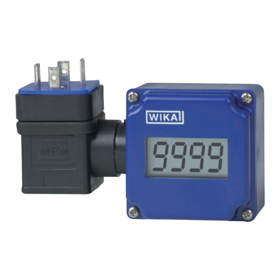
- Page 1 Operating instructions Betriebsanleitung Attachable indicator model A-AI-1 Aufsteckanzeige Typ A-AI-1 Attachable indicator model A-AI-1...
- Page 2 3 - 24 Betriebsanleitung Typ A-AI-1 Seite 25 - 45 Further languages can be found at www.wika.com. © 11/2003 WIKA Alexander Wiegand SE & Co. KG All rights reserved. / Alle Rechte vorbehalten. WIKA is a registered trademark in various countries. ®...
-
Page 3: Table Of Contents
5.3 Configuration of the display 6. Faults 7. Maintenance and cleaning 7.1 Maintenance 7.2 Cleaning 8. Dismounting, return and disposal 8.1 Dismounting 8.2 Return 8.3 Disposal 9. Specifications Declarations of conformity can be found online at www.wika.com. WIKA operating instructions attachable indicator model A-AI-1... -
Page 4: General Information
1. General information 1. General information The model A-AI-1 attachable indicator described in the operating ■ instructions has been manufactured using state-of-the-art technology. All components are subject to stringent quality and environmental criteria during production. Our management systems are certified to ISO 9001 and ISO 14001. -
Page 5: Design And Function
The display of the measured value is made on a 4-digit LC display with a maximum indication range of -1999 ... 9999 digits. The A-AI-1 has been designed for the connection of any transmitter (with 4 ... 20 mA output). The matching of the indicator range to the transmitter is made without external aids through the direct input of the upper and lower measuring range limits and the decimal point position. -
Page 6: Safety
... points out useful tips, recommendations and information for efficient and trouble-free operation. 3.2 Intended use The model A-AI-1 attachable indicator is suitable for insertion between a transmitter and the corresponding output connector (angular connector). This instrument is not permitted to be used in hazardous areas! The instrument has been designed and built solely for the intended use described here, and may only be used accordingly. -
Page 7: Improper Use
The trouble-free function and operational safety of the instrument can only be guaranteed if the general safety measures and the instrument-specific safety instructions given in this manual are followed. WIKA operating instructions attachable indicator model A-AI-1... -
Page 8: Personnel Qualification
▶ Keep unqualified personnel away from hazardous areas. Skilled electrical personnel Skilled electrical personnel are understood to be personnel who, based on their technical training, know-how and experience as well as their knowledge WIKA operating instructions attachable indicator model A-AI-1... -
Page 9: Labelling, Safety Marks
Input current Symbols Before mounting and commissioning the instrument, ensure you read the operating instructions! Do not dispose of with household waste. Ensure a proper disposal in accordance with national regulations. WIKA operating instructions attachable indicator model A-AI-1... -
Page 10: Transport, Packaging And Storage
Avoid exposure to the following factors: Direct sunlight or proximity to hot objects ■ Mechanical vibration, mechanical shock (putting it down hard) ■ Soot, vapour, dust and corrosive gases ■ Hazardous environments, flammable atmospheres ■ WIKA operating instructions attachable indicator model A-AI-1... -
Page 11: Commissioning, Operation
The assignment of the angular connector is designed for the most commonly used configuration for the respective input signal. Since this assignment is not standardised, it can happen that the assignment for the connected transmitter does not match the assignment of the attachable indicator. WIKA operating instructions attachable indicator model A-AI-1... - Page 12 Not connected Not connected In the angular connector, pin contact 2 is directly connected with the female contact. Between pin contact 1 (+) and female contact 1 (-) is the A-AI-1. Pin contacts Female connector If the transmitter to be connected does not have the negative power terminal...
-
Page 13: Configuration Of The Display
The display is optionally available with the buttons on the front of the instrument. The configuration is carried out using these buttons, so that the case does not have to be opened. WIKA operating instructions attachable indicator model A-AI-1... - Page 14 To switch to the next parameter, press button 1. The name of the parameter will appear in the display. If, during input, no button is pressed for 60 seconds, the configuration of the instrument will be interrupted. Previously saved values will not be lost. WIKA operating instructions attachable indicator model A-AI-1...
- Page 15 100 is displayed). When the measuring limits are exceeded (at either end), independently of the limit settings, the corresponding error message appears (“Err.1” or “Err.2”). The measuring limits are between approx. 3.7 and 20.8 mA. WIKA operating instructions attachable indicator model A-AI-1...
- Page 16 The input of the slope correction factor is made in %. The displayed value is calculated as per the following equation: Display = (measured value - Offset - di.Lo) * (1 + slope correction [% / 100] ) + di.Lo WIKA operating instructions attachable indicator model A-AI-1...
- Page 17 To delete the Press buttons “CLr” will briefly be shown in the display, Min./Max. 2 and 3 the Min./Max. value will be reset to the values simultaneously current display value for 2 s WIKA operating instructions attachable indicator model A-AI-1...
-
Page 18: Faults
Current less than 4 mA signal is once more within the permissible Sensor break permissible limits. range Check the transmitter and the instrument configuration (e.g. input signal). WIKA operating instructions attachable indicator model A-AI-1... -
Page 19: Maintenance And Cleaning
For contact details, please see chapter 1 “General information” or the back page of the operating instructions. 7.1 Maintenance This attachable indicator is maintenance-free. Repairs must only be carried out by the manufacturer. WIKA operating instructions attachable indicator model A-AI-1... -
Page 20: Cleaning
Observe the information in the material safety data sheet for the corresponding medium. ▶ Wash or clean the dismounted instrument, in order to protect persons and the environment from exposure to residual media. WIKA operating instructions attachable indicator model A-AI-1... -
Page 21: Dismounting
8.2 Return Strictly observe the following when shipping the instrument: All instruments delivered to WIKA must be free from any kind of hazardous substances (acids, bases, solutions, etc.) and must therefore be cleaned before being returned. -
Page 22: Disposal
Approx. 48.5 x 48.5 x 35.5 mm [1.79 x 1.79 x 1.40 in](with angular connector) Approx. 90 x 50.5 x 39.5 mm [3.54 x 3.54 x 1.56 in] (without angular connector) Weight Approx. 80 g WIKA operating instructions attachable indicator model A-AI-1... - Page 23 Relative humidity < 80 % r. h. non-condensing Temperature effect on the 0.1 % / 10 K display For further specifications, see WIKA data sheet AC 80.07 and the order documentation. Dimensions in mm WIKA operating instructions attachable indicator model A-AI-1...
- Page 24 WIKA operating instructions attachable indicator model A-AI-1...
- Page 25 5.2 Anschlussbelegung 5.3 Konfiguration der Anzeige 6. Störungen 7. Wartung und Reinigung 7.1 Wartung 7.2 Reinigung 8. Demontage, Rücksendung und Entsorgung 8.1 Demontage 8.2 Rücksendung 8.3 Entsorgung 9. Technische Daten Konformitätserklärungen finden Sie online unter www.wika.de. WIKA-Betriebsanleitung Aufsteckanzeige Typ A-AI-1...
-
Page 26: Allgemeines
1. Allgemeines 1. Allgemeines Die in der Betriebsanleitung beschriebene Aufsteckanzeige Typ A-AI-1 ■ wird nach den neuesten Erkenntnissen gefertigt. Alle Komponenten unterliegen während der Fertigung strengen Qualitäts- und Umweltkriterien. Unsere Managementsysteme sind nach ISO 9001 und ISO 14001 zertifiziert. Diese Betriebsanleitung gibt wichtige Hinweise zum Umgang mit dem ■... -
Page 27: Aufbau Und Funktion
Messstrom. Die Anzeige des Messwertes erfolgt auf einem 4-stelligen LC-Display mit einem maximalen Display-Anzeigebereich von -1999 ... 9999 Digit. Die A-AI-1 ist für den Anschluss beliebiger Messumformer (mit 4 ... 20 mA-Ausgang) ausgelegt. Die Bereichsanpassung des Anzeigegerä- tes an den Transmitter erfolgt ohne externe Hilfsmittel durch direkte Eingabe der oberen und unteren Messbereichsgrenze und der Dezimalpunktposi- tion. -
Page 28: Sicherheit De
… hebt nützliche Tipps und Empfehlungen sowie Informationen für einen effizienten und störungsfreien Betrieb hervor. 3.2 Bestimmungsgemäße Verwendung Die Aufsteckanzeige Typ A-AI-1 ist zum Zwischenstecken zwischen einem Transmitter und dem dazugehörigen Ausgangsstecker (Winkelstecker) geeignet. Dieses Gerät ist nicht für den Einsatz in explosionsgefährdeten Bereichen zugelassen! Das Gerät ist ausschließlich für den hier beschriebenen... -
Page 29: Fehlgebrauch
Dieses Gerät ist gemäß den Sicherheitsbestimmungen für elektronische Messgeräte gebaut und geprüft. Die einwandfreie Funktion und Betriebssicherheit des Gerätes kann nur dann gewährleistet werden, wenn bei der Benutzung die allgemein üblichen Sicherheitsvorkehrungen sowie die gerätespezifischen Sicherheitshinweise in dieser Bedienungsanleitung beachtet werden. WIKA-Betriebsanleitung Aufsteckanzeige Typ A-AI-1... -
Page 30: Personalqualifikation
Fachpersonal nachfolgend beschriebener Qualifikation durchführen lassen. Elektrofachpersonal Das Elektrofachpersonal ist aufgrund seiner fachlichen Ausbildung, Kenntnisse und Erfahrungen sowie Kenntnis der landesspezifischen Vorschriften, geltenden Normen und Richtlinien in der Lage, Arbeiten an elektrischen Anlagen auszuführen und mögliche Gefahren selbstständig WIKA-Betriebsanleitung Aufsteckanzeige Typ A-AI-1... -
Page 31: Beschilderung, Sicherheitskennzeichnungen
Spannungsversorgung Bestellnummer Herstellungsdatum Seriennummer Bestellcode Eingangsstrom Symbole Vor Montage und Inbetriebnahme des Gerätes unbedingt die Betriebsanleitung lesen! Nicht mit dem Hausmüll entsorgen. Für eine geordnete Entsorgung gemäß nationaler Vorgaben sorgen. WIKA-Betriebsanleitung Aufsteckanzeige Typ A-AI-1... -
Page 32: Transport, Verpackung Und Lagerung
Feuchte: 0 ... 80 % r. F. (keine Betauung) ■ Folgende Einflüsse vermeiden: Direktes Sonnenlicht oder Nähe zu heißen Gegenständen ■ Mechanische Vibration, mechanischer Schock (hartes Aufstellen) ■ Ruß, Dampf, Staub und korrosive Gase ■ Explosionsgefährdete Umgebung, entzündliche Atmosphären ■ WIKA-Betriebsanleitung Aufsteckanzeige Typ A-AI-1... -
Page 33: Inbetriebnahme, Betrieb
5.2 Anschlussbelegung Die Winkelsteckerbelegung ist auf die gebräuchlichste Belegung des jeweiligen Eingangssignals ausgelegt. Da diese Belegung jedoch nicht genormt ist, kann es vorkommen, dass die Belegung des anzuschließenden Transmitters nicht mit der Belegung der Aufsteckanzeige übereinstimmt. WIKA-Betriebsanleitung Aufsteckanzeige Typ A-AI-1... - Page 34 Nicht verbunden Nicht verbunden Nicht verbunden Im Winkelstecker ist der Stiftkontakt 2 direkt mit der Buchse verbunden. Zwischen Stiftkontakt 1 (+) und Buchsenkontakt 1 (-) befindet sich die A-AI-1. Stiftkontakte Buchse Hat der anzuschließende Transmitter den negativen Versorgungsanschluss nicht auf Kontakt 2 und den positiven Versorgungsanschluss nicht auf Kontakt 1, so muss die Belegung des Winkelsteckers der A-AI-1 und des externen Winkelsteckers dementsprechend angepasst werden.
-
Page 35: Konfiguration Der Anzeige
Hierzu die vier Schrauben an den Ecken des Gehäuses lösen. Nach Beendigung der Konfiguration die Dichtung korrekt einlegen und den Deckel montieren. Optional ist die Anzeige mit Tasten an der Gerätevorderseite verfügbar. Die Konfiguration erfolgt mittels dieser Tasten, sodass das Gehäuse nicht geöffnet werden muss. WIKA-Betriebsanleitung Aufsteckanzeige Typ A-AI-1... - Page 36 Um zum nächsten Parameter zu wechseln, Taste 1 drücken. Der Name des Parameters erscheint im Display. Wird bei der Eingabe länger als 60 Sekunden keine Taste gedrückt, so wird die Konfiguration des Gerätes abgebrochen. Bereits gespeicherte Werte gehen nicht verloren. WIKA-Betriebsanleitung Aufsteckanzeige Typ A-AI-1...
- Page 37 5. Inbetriebnahme, Betrieb Parameter der Aufsteckanzeige Typ A-AI-1 Parameter Werte Bedeutung Taste 1 Tasten 2 und 3 Position des Dezimalpunktes (decimal point) ---- Max. Display-Anzeigebereich: -1999 … 9999 ---.- Max. Display-Anzeigebereich: -199,9 … 999,9 --.-- Max. Display-Anzeigebereich: -19,99 … 99,99 -.---...
- Page 38 Steigung (scale) -5.00 … 5.00 Die Eingabe der Steigungskorrektur erfolgt in %. Der Anzeigewert wird nach folgender Formel berechnet: Anzeige = (gemessener Wert - Offset - di.Lo) * (1 + Steigungskorrektur [% / 100] ) + di.Lo WIKA-Betriebsanleitung Aufsteckanzeige Typ A-AI-1...
- Page 39 2 s der Max.-Wert angezeigt Löschen Taste 2 und 3 es wird in der Anzeige kurz „CLr“ des Min-/ gleichzeitig für angezeigt, der Min.-/Max.-Wert wird auf Max.-Wertes 2 s drücken den aktuellen Anzeigewert zurückgesetzt WIKA-Betriebsanleitung Aufsteckanzeige Typ A-AI-1...
-
Page 40: Störungen
(z. B.: Eingangssignal). Err.2 Eingangssignal zu klein Die Fehlermeldung wird Messbereich bzw. negativ zurückgesetzt, sobald das unterschritten Strom kleiner 4 mA Eingangssignal wieder Fühlerbruch innerhalb der zugelassenen Grenzen liegt. Messumformer und Gerätekonfiguration überprüfen (z. B.: Eingangssignal). WIKA-Betriebsanleitung Aufsteckanzeige Typ A-AI-1... -
Page 41: Wartung Und Reinigung
Skalierung fehlerhaft Einstellung und Eingangssignal Er.11 Wert konnte überprüfen nicht berechnet werden 7. Wartung und Reinigung Kontaktdaten siehe Kapitel 1 „Allgemeines“ oder Rückseite der Betriebsanleitung. 7.1 Wartung Diese Aufsteckanzeige ist wartungsfrei. Reparaturen sind ausschließlich vom Hersteller durchzuführen. WIKA-Betriebsanleitung Aufsteckanzeige Typ A-AI-1... -
Page 42: Reinigung
Messstoffreste im ausgebauten Gerät können zur Gefährdung von Personen, Umwelt und Einrichtung führen. ▶ Angaben im Sicherheitsdatenblatt für den entsprechenden Messstoff beachten. ▶ Ausgebautes Gerät spülen bzw. säubern, um Personen und Umwelt vor Gefährdung durch anhaftende Messstoffreste zu schützen. WIKA-Betriebsanleitung Aufsteckanzeige Typ A-AI-1... -
Page 43: Demontage
Hierzu die Schaube aus dem Originalzubehör des Transmitters verwenden, diese ist kürzer. 8.2 Rücksendung Beim Versand des Gerätes unbedingt beachten: Alle an WIKA gelieferten Geräte müssen frei von Gefahrstoffen (Säuren, Laugen, Lösungen, etc.) sein und sind daher vor der Rücksendung zu reinigen. WARNUNG! Körperverletzungen, Sach- und Umweltschäden durch... -
Page 44: Entsorgung
IP65, bei sachgerecht montiertem Winkelstecker Abmessungen Ca. 48,5 x 48,5 x 35,5 mm [1,79 x 1,79 x 1,40 in] (mit Winkelstecker) Ca. 90 x 50,5 x 39,5 mm [3,54 x 3,54 x 1,56 in] (ohne Winkelstecker) Gewicht Ca. 80 g WIKA-Betriebsanleitung Aufsteckanzeige Typ A-AI-1... - Page 45 -20 ... +70 °C [-4 ... +158 °F] Relative Luftfeuchte < 80 % r. F. nicht kondensierend Temperatureinfluss auf die 0,1 % / 10 K Anzeige Weitere technische Daten siehe WIKA-Datenblatt AC 80.07 und Bestellunterlagen. Abmessungen in mm WIKA operating instructions attachable indicator model A-AI-1...
- Page 46 WIKA operating instructions attachable indicator model A-AI-1...
- Page 47 WIKA operating instructions attachable indicator model A-AI-1...
- Page 48 WIKA subsidiaries worldwide can be found online at www.wika.com. WIKA Niederlassungen weltweit finden Sie online unter www.wika.de. Importer for UK WIKA Alexander Wiegand SE & Co. KG WIKA Instruments Ltd Alexander-Wiegand-Strasse 30 Unit 6 and 7 Goya Business park 63911 Klingenberg • Germany The Moor Road Tel.
Need help?
Do you have a question about the A-AI-1 and is the answer not in the manual?
Questions and answers