
Related Manuals for WIKA A2G-25


Summary of Contents for WIKA A2G-25
- Page 1 Operating instructions Betriebsanleitung Air flow meter, model A2G-25 Volumenstrommessgerät, Typ A2G-25 Model A2G-25...
- Page 2 Operating instructions model A2G-25 Page 3 - 44 Betriebsanleitung Typ A2G-25 Seite 45 - 85 © 01/2011 WIKA Alexander Wiegand SE & Co. KG All rights reserved. / Alle Rechte vorbehalten. WIKA is a registered trademark in various countries. ® WIKA ist eine geschützte Marke in verschiedenen Ländern.
-
Page 3: Table Of Contents
3. Safety 4. Transport, packaging and storage 5. Commissioning, operation 6. Menu navigation 7. Maintenance and cleaning 8. Dismounting, return and disposal 9. Specifications 10. Accessories Declarations of conformity can be found online at www.wika.com. WIKA operating instructions model A2G-25... -
Page 4: General Information
The general terms and conditions contained in the sales ■ documentation shall apply. Subject to technical modifications. ■ Further information: ■ - Internet address: www.wika.de / www.wika.com www.air2guide.com - Relevant data sheet: SP 69.04 WIKA operating instructions model A2G-25... -
Page 5: Design And Function
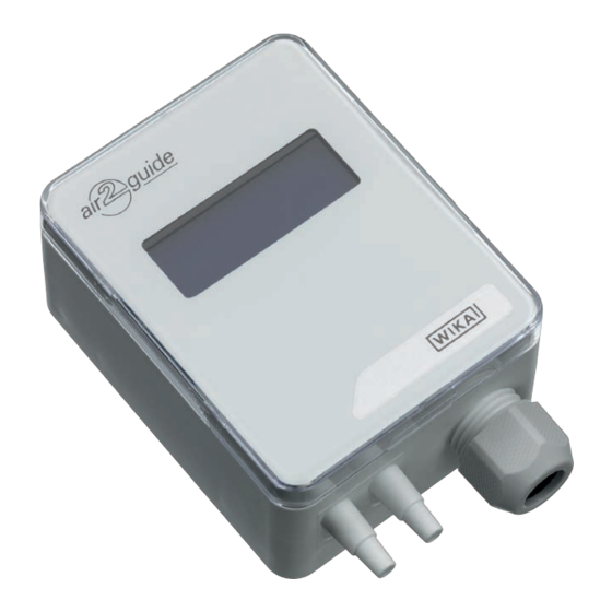
Connecting nozzle (ABS), for hoses with inner diameter 4 or 6 mm 2.2 Description The model A2G-25 air flow meter is used for measuring air flows of gaseous media in ventilation and air-conditioning applications. It is based on the piezoresistive measuring principle. - Page 6 2.3 Dimensions in mm 40405589.02 2.4 Scope of delivery Air flow meter ■ 2 mounting screws ■ 2 duct connectors (option) ■ 2 x 2 m PVC measuring hose (option) ■ Cross-check scope of delivery with delivery note. WIKA operating instructions model A2G-25...
-
Page 7: Safety
The air flow meter is used for: Measurement of air flows of radial ventilators ■ Measurement of air flows in ventilation pipes and ducts in conjunction ■ with the A2G-FM measuring probe Measurement of differential pressures ■ WIKA operating instructions model A2G-25... - Page 8 Improper handling or operation of the instrument outside of its technical specifications requires the instrument to be taken out of service immediately and inspected by an authorised WIKA service engineer. The manufacturer shall not be liable for claims of any type based on operation contrary to the intended use.
- Page 9 The skilled electrical personnel have been specifically trained for the work environment they are working in and know the relevant standards and regulations. The skilled electrical personnel must comply with current legal accident prevention regulations. WIKA operating instructions model A2G-25...
- Page 10 Supply: DC 24 V / AC 24 V ±10 % < 1 W Made in EU E-Nr. 66209848 Model Measuring range Output signal Power supply Serial number Before mounting and commissioning the instrument, ensure you read the operating instructions! WIKA operating instructions model A2G-25...
-
Page 11: Transport, Packaging And Storage
Avoid exposure to the following factors: Direct sunlight or proximity to hot objects ■ Mechanical vibration, mechanical shock (putting it down hard) ■ Soot, vapour, humidity, dust and corrosive gases ■ Hazardous environments, flammable atmospheres ■ WIKA operating instructions model A2G-25... -
Page 12: Commissioning, Operation
Should a failure occur, aggressive media with extremely high temperature and under high pressure or vacuum may be present at the instrument. ▶ For these media, in addition to all standard regulations, the appropriate existing codes or regulations must also be followed. WIKA operating instructions model A2G-25... - Page 13 1. Instrument fixing at the desired mounting location (see chapter 5.1 „Instrument mounting“) 2. Opening the instrument cover, feeding the connection cable through the cable gland and connecting the wires to the terminal block (see chapter 5.2 „Electrical mounting“) WIKA operating instructions model A2G-25...
- Page 14 1. Select a mounting location (duct, wall, panel). 2. Remove the case cover and use the screw holes as a template. 3. Mount with suitable screws. Instrument fixing Instrument orientation WIKA operating instructions model A2G-25...
- Page 15 5. Commissioning, operation Application-related connections Static pressure Filter Ventilator measurement monitoring monitoring WIKA operating instructions model A2G-25...
- Page 16 (SELV). As a rule, operate the air flow meter in the middle of the measuring range, since deviations can occur at the range limits. Operate the A2G-25 with a constant operating voltage (±0.2 V) and ambient temperature. Prevent current/voltage spikes from switching the power supply on or off.
- Page 17 5.0 V 24 V 4 ... 20 mA 4 ... 20 mA 0.0 V Time axis t [s] Pressure P Signal [I] 100 % 20.0 mA 50 % 12.0 mA 4.0 mA Time axis t [s] WIKA operating instructions model A2G-25...
- Page 18 5. Commissioning, operation 5.3 Output signal setting The analogue output signal of the model A2G-25 air flow meter can be set between 0 ... 10 V and 4 ... 20 mA. The setting can be made via jumpers on the printed circuit board.
- Page 19 During the zero point setting the display and output value remains at the last measured value. The automatic zero point setting takes 3 seconds and is repeated every 10 minutes. Reset Reset (Zurücksetzen) WIKA operating instructions model A2G-25...
-
Page 20: Menu Navigation
Use “UP” or “DOWN” to find the desired ventilator manufacturer. MANUFACTURER Rosenberg ▶ The manufacturers are shown in a row Move the “SELECT” button once, shortly, in order to accept the displayed manufacturer. MANUFACTURER Rosenberg WIKA operating instructions model A2G-25... - Page 21 Use “UP” or “DOWN” to find the desired unit. FORMULA UNIT ▶ Selection is displayed m3/s Move the “SELECT” button once, shortly, in order to accept the selection. FORMULA UNIT m3/s When using the model A2G-FM measuring probe, activate the unit l/s. WIKA operating instructions model A2G-25...
- Page 22 Move the “SELECT” button to the left and right to K-VALUE 0061.130 select the decimal point. ▶ The “K-VALUE” is displayed Move the “SELECT” button once, shortly, in order to accept the selection. K-VALUE 0061.130 WIKA operating instructions model A2G-25...
- Page 23 Use “UP” or “DOWN” to find the desired pressure unit. ▶ Selection is displayed PRESS.UNIT mbar Move the “SELECT” button once, shortly, in order to accept the selection. PRESS.UNIT mbar When using the model A2G-FM measuring probe, activate the unit l/s. WIKA operating instructions model A2G-25...
- Page 24 0.8 ... 8.0 A2G-25-5000 Pa 500 ... 5,000 0.5 ... 5.0 5.0 ... 50 50 ... 500 2.0 ... 20 700 ... 7,000 0.7 ... 7.0 7.0 ... 70 70 ... 700 2.5 ... 30 A2G-25-7000 Pa WIKA operating instructions model A2G-25...
- Page 25 ▶ Selection flashes Use “UP” or “DOWN” to find the desired unit. ▶ Selection is displayed FLOW UNIT Move the “SELECT” button once, shortly, in order to accept the selection. FLOW UNIT WIKA operating instructions model A2G-25...
- Page 26 V OUTPUT MAX 30,000 m3/s Max. air flow in connection with the selected measuring instrument variant Unit Range 0.025 ... 50 100 ... 200,000 50 ... 100,000 25 ... 50,000 1.0 ... 100 2,000 ... 20,000 WIKA operating instructions model A2G-25...
- Page 27 Selection is displayed 18 s Move the “SELECT” button once, shortly, in order to accept the selection. RESPONSE TIME 18 s 9. Press the “SELECT” button in order to exit the menu. SELECT EXIT MENU WIKA operating instructions model A2G-25...
- Page 28 Use “UP” or “DOWN” to find the desired ventilator manufacturer. MANUFACTURER Rosenberg ▶ The manufacturers are shown in a row Move the “SELECT” button once, shortly, in order to accept the displayed manufacturer. MANUFACTURER Rosenberg WIKA operating instructions model A2G-25...
- Page 29 Use “UP” or “DOWN” to find the desired unit. ▶ Selection is displayed FORMULA UNIT m3/s Move the “SELECT” button once, shortly, in order to accept the selection. FORMULA UNIT m3/s When using the model A2G-FM measuring probe, activate the unit l/s. WIKA operating instructions model A2G-25...
- Page 30 Move the “SELECT” button to the left and right to K-VALUE select the decimal point. 0061.130 ▶ The “K-VALUE” is displayed Move the “SELECT” button once, shortly, in order to accept the selection. K-VALUE 0061.130 WIKA operating instructions model A2G-25...
- Page 31 Use “UP” or “DOWN” to find the desired pressure unit. ▶ Selection is displayed PRESS.UNIT mbar Move the “SELECT” button once, shortly, in order to accept the selection. PRESS.UNIT mbar When using the model A2G-FM measuring probe, activate the unit l/s. WIKA operating instructions model A2G-25...
- Page 32 ▶ Selection flashes Use “UP” or “DOWN” to find the desired unit. ▶ Selection is displayed FLOW UNIT Move the “SELECT” button once, shortly, in order to accept the selection. FLOW UNIT WIKA operating instructions model A2G-25...
- Page 33 ▶ Selection flashes Use “UP” or “DOWN” to find the desired response time. RESPONSETIME 18 s ▶ Selection is displayed Move the “SELECT” button once, shortly, in order to accept the selection. RESPONSETIME 18 s WIKA operating instructions model A2G-25...
- Page 34 Modbus address selection. ® ▶ Selection flashes Use “UP” or “DOWN” to find the desired response time. ▶ ADDRESS Selection is displayed Move the “SELECT” button once, shortly, in order to accept the selection. ADDRESS WIKA operating instructions model A2G-25...
- Page 35 ▶ Selection flashes Use “UP” or “DOWN” to find the desired baud rate. ▶ BAUD RATE Selection is displayed 19200 Move the “SELECT” button once, shortly, in order to accept the selection. BAUD RATE 19200 WIKA operating instructions model A2G-25...
- Page 36 PARITY BIT Selection is displayed EVEN Move the “SELECT” button once, shortly, in order to accept the selection. PARITY BIT EVEN 10. Press the “SELECT” button in order to exit the menu. SELECT EXIT MENU WIKA operating instructions model A2G-25...
-
Page 37: Maintenance And Cleaning
2. Use the requisite protective equipment. 3. Clean the instrument with a moist cloth (soapy water). Electrical connections must not come into contact with moisture! WIKA operating instructions model A2G-25... -
Page 38: Dismounting, Return And Disposal
▶ Observe the information in the material safety data sheet for the corresponding medium. ▶ Wash or clean the dismounted instrument, in order to protect persons and the environment from exposure to residual media. WIKA operating instructions model A2G-25... - Page 39 When dismounting, there is a danger from aggressive media and high pressures. ▶ Observe the information in the material safety data sheet for the corresponding medium. ▶ Dismount the instrument when there is no pressure. WIKA operating instructions model A2G-25...
- Page 40 8. Dismounting, return and disposal 8.2 Return Strictly observe the following when shipping the instrument: All instruments delivered to WIKA must be free from any kind of hazardous substances (acids, bases, solutions, etc.) and must therefore be cleaned before being returned.
-
Page 41: Specifications
9. Specifications 9. Specifications Air flow meter, model A2G-25 Measuring element Piezo measuring cell Measuring range 0 ... 1,000, 0 ... 2,000, 0 ... 5,000, 0 ... 7,000 Pa 0 ... 1,000 Pa = pressure < 125 Pa = ±2 Pa + 1 % Accuracy Pressure >... - Page 42 - 1 stop bit Baud rate Adjustable in the configuration Modbus addresses 1 ... 247 addresses - adjustable in the configuration ® For further specifications see WIKA data sheet SP 69.04 and the order documentation. WIKA operating instructions model A2G-25...
-
Page 43: Accessories
PVC hose, inner diameter 6 mm, roll at 25 m 40217850 Silicone hose, inner diameter 4 mm, roll at 25 m 40208940 Silicone hose, inner diameter 6 mm, roll at 25 m 40208958 Duct connector for hose 4 and 6 mm 40217507 WIKA operating instructions model A2G-25... - Page 44 WIKA operating instructions model A2G-25...
- Page 45 2. Aufbau und Funktion 3. Sicherheit 4. Transport, Verpackung und Lagerung 5. Inbetriebnahme, Betrieb 6. Menüführung 7. Wartung und Reinigung 8. Demontage, Rücksendung und Entsorgung 9. Technische Daten 10. Zubehör Konformitätserklärungen finden Sie online unter www.wika.de. WIKA Betriebsanleitung Typ A2G-25...
-
Page 46: Allgemeines
Das Fachpersonal muss die Betriebsanleitung vor Beginn aller Arbei- ■ ten sorgfältig durchgelesen und verstanden haben. Es gelten die allgemeinen Geschäftsbedingungen in den Verkaufsun- ■ terlagen. Technische Änderungen vorbehalten. ■ Weitere Informationen: ■ - Internet-Adresse: www.wika.de / www.wika.com www.air2guide.com - Zugehöriges Datenblatt: SP 69.04 WIKA Betriebsanleitung Typ A2G-25... -
Page 47: Aufbau Und Funktion
Anschlussstutzen (ABS), für Schläuche mit Innendurchmesser 4 oder 6 mm 2.2 Beschreibung Das Volumenstrommessgerät Typ A2G-25 wird zur Messung von Volumenströmen gasförmiger Medien in der Luft- und Klimatechnik verwendet. Es funktioniert nach dem piezoresistiven Messprinzip. Elektrische analoge Ausgangssignale für beide Messgrößen (DC 0 ... - Page 48 (z. B. ebm-papst, ZIEHL-ABEGG, Nicotra-Gebhardt, Rosenberg, Fläkt-Woods, Comefri). 2.3 Abmessungen in mm 40405589.02 2.4 Lieferumfang Volumenstrommessgerät ■ 2 Befestigungsschrauben ■ 2 Kanalanschlussnippel (Option) ■ 2 x 2 m PVC-Messschlauch (Option) ■ Lieferumfang mit dem Lieferschein abgleichen. WIKA Betriebsanleitung Typ A2G-25...
-
Page 49: Sicherheit
Betrieb hervor. 3.2 Bestimmungsgemäße Verwendung Das Volumenstrommessgerät dient zur: Messung von Volumenströmen von Radial-Ventilatoren ■ Messung von Volumenströmen in Lüftungsrohren und Kanälen in ■ Verbindung mit der Messsonde Typ A2G-FM Messung von Differenzdrücken ■ WIKA Betriebsanleitung Typ A2G-25... - Page 50 Die technischen Spezifikationen in dieser Betriebsanleitung sind einzuhalten. Eine unsachgemäße Handhabung oder ein Betreiben des Gerätes außerhalb der technischen Spezifikationen macht die sofortige Stilllegung und Überprüfung durch einen autorisierten WIKA-Servicemit- arbeiter erforderlich. Ansprüche jeglicher Art aufgrund von nicht bestimmungsgemäßer Verwendung sind ausgeschlossen.
- Page 51 Das Elektrofachpersonal ist speziell für das Arbeitsumfeld, in dem es tätig ist, ausgebildet und kennt die relevanten Normen und Bestimmungen. Das Elektrofachpersonal muss die Bestimmungen der geltenden gesetzlichen Vorschriften zur Unfall- verhütung erfüllen. WIKA Betriebsanleitung Typ A2G-25...
- Page 52 Supply: DC 24 V / AC 24 V ±10 % < 1 W E-Nr. 66209848 Made in EU Messbereich Ausgangssignal Hilfsenergie Seriennummer Vor Montage und Inbetriebnahme des Gerätes unbedingt die Betriebsanleitung lesen! WIKA Betriebsanleitung Typ A2G-25...
-
Page 53: Transport, Verpackung Und Lagerung
Lagertemperatur: -20 ... +70 °C ■ Folgende Einflüsse vermeiden: Direktes Sonnenlicht oder Nähe zu heißen Gegenständen ■ Mechanische Vibration, mechanischer Schock (hartes Aufstellen) ■ Ruß, Dampf, Feuchtigkeit, Staub und korrosive Gase ■ Explosionsgefährdete Umgebung, entzündliche Atmosphären ■ WIKA Betriebsanleitung Typ A2G-25... -
Page 54: Inbetriebnahme, Betrieb
VORSICHT! Beschädigung des Gerätes Bei Arbeiten mit offenen Schaltkreisen (Leiterplatten) besteht die Gefahr empfindliche elektronische Bauteile durch elektro- statische Entladung zu beschädigen. ▶ Die ordnungsgemäße Verwendung geerdeter Arbeitsflä- chen und persönlicher Armbänder ist erforderlich. WIKA Betriebsanleitung Typ A2G-25... - Page 55 Gerät lebensgefährliche Spannungen auftre- ten! 1. Gerätebefestigung an der gewünschten Montagestelle (siehe Kapitel 5.1 „Gerätemontage“) 2. Öffnen des Gerätedeckels, Durchführung des Anschlusskabels durch die Kabelverschraubung und Anschluss der Drähte an den Klemmenblock (siehe Kapitel 5.2 „Elektrische Montage“) WIKA Betriebsanleitung Typ A2G-25...
- Page 56 Den Differenzdrucktransmitter auf einer geeigneten vertikalen Fläche aufschrauben und waagerecht mit den beiliegenden Befestigungs- schrauben befestigen. 1. Montageort wählen (Kanal, Wand, Panel). 2. Gehäusedeckel entfernen und die Schraubenlöcher als Schablone verwenden. 3. Mit geeigneten Schrauben montieren. Gerätebefestigung Geräteausrichtung WIKA Betriebsanleitung Typ A2G-25...
- Page 57 5. Inbetriebnahme, Betrieb Anwendungsbezogene Anschlüsse Statische Filter- Ventilator- Druckmessung überwachung überwachung WIKA Betriebsanleitung Typ A2G-25...
- Page 58 Das Volumenstrommessgerät in der Regel in der Messbereichsmitte betreiben, da an den Messbereichsendpunkten erhöhte Abweichungen auftreten können. A2G-25 bei einer konstanten Betriebsspannung (±0,2 V) und Umgebungstemperatur betreiben. Strom-/Spannungsspitzen beim Ein-/ Ausschalten der Hilfsenergie bauseitig vermeiden. Für die CE-Konformität ist ein ordnungsgemäß geerdetes Schutzkabel erforderlich.
- Page 59 20.0 mA 50 % 12.0 mA 4.0 mA Zeitachse t [s] Philipp Kottmann 29.04.2015 Signal_A2G-25.docx Erstellt: Datei: Seite MANOMETER AG T +41(0)41 919 72 72 Industriestrasse 11 F +41(0)41 919 72 73 CH-6285 Hitzkirch E-Mail info@manometer.ch WIKA Betriebsanleitung Typ A2G-25...
- Page 60 5. Inbetriebnahme, Betrieb 5.3 Einstellen des Ausgangssignals Das analoge Ausgangssignal des Volumenstrommessgerätes Typ A2G-25 ist zwischen 0 ... 10 V und 4 ... 20 mA einstellbar. Die Einstellung kann über Brücken auf der Platine vorgenommen werden. 4-20 mA Installation der Brücken (Farbe dunkelgrau signalisiert die Brückenplatzierung)
- Page 61 Nullpunktdrift des piezoresistiven Sensorelements. Während der Nullpunkteinstellung bleibt der Anzeige- und Ausgangswert beim letzten gemessenen Wert stehen. Die automatische Nullpunktein- stellung dauert 3 Sekunden und wird alle 10 Minuten wiederholt. Reset (Zurücksetzen) Reset (Zurücksetzen) WIKA Betriebsanleitung Typ A2G-25...
-
Page 62: Menüführung
Auswahl „Fläkt Woods“ blinkt „UP“ oder „DOWN“ verwenden, um den gewünschten Ventilatorhersteller zu finden. MANUFACTURER Rosenberg ▶ Die Hersteller werden der Reihe nach angezeigt Die Taste „SELECT“ einmal kurz bewegen, um den angezeigten Hersteller zu bestätigen. MANUFACTURER Rosenberg WIKA Betriebsanleitung Typ A2G-25... - Page 63 „UP“ oder „DOWN“ verwenden, um die gewünschte Einheit zu finden. FORMULA UNIT ▶ m3/s Auswahl wird angezeigt Taste „SELECT“ einmal kurz bewegen, um die Auswahl zu bestätigen. FORMULA UNIT m3/s Bei Verwendung der Messsonde Typ A2G-FM die Einheit l/s aktivieren. WIKA Betriebsanleitung Typ A2G-25...
- Page 64 „UP“ oder „DOWN“ verwenden, um die gewünschte Ziffern einzugeben. K-VALUE 0061.130 Taste „SELECT“ nach links und rechts bewegen, um die Dezimalstellen zu wechseln. ▶ Der „K-VALUE“ wird angezeigt Taste „SELECT“ einmal kurz bewegen, um die Auswahl zu bestätigen. K-VALUE 0061.130 WIKA Betriebsanleitung Typ A2G-25...
- Page 65 „UP“ oder „DOWN“ verwenden, um die gewünschte Druckeinheit zu finden. PRESS.UNIT ▶ Auswahl wird angezeigt mbar Taste „SELECT“ einmal kurz bewegen, um die Auswahl zu bestätigen. PRESS.UNIT mbar Bei Verwendung der Messsonde Typ A2G-FM die Einheit l/s aktivieren. WIKA Betriebsanleitung Typ A2G-25...
- Page 66 0,8 ... 8,0 A2G-25-5000 Pa 500 ... 5.000 0,5 ... 5,0 5,0 ... 50 50 ... 500 2,0 ... 20 A2G-25-7000 Pa 700 ... 7.000 0,7 ... 7,0 7,0 ... 70 70 ... 700 2,5 ... 30 WIKA Betriebsanleitung Typ A2G-25...
- Page 67 Auswahl der Einheit zu aktivieren. m3/s ▶ Auswahl blinkt „UP“ oder „DOWN“ verwenden, um die gewünschte FLOW UNIT Einheit zu finden. ▶ Auswahl wird angezeigt Taste „SELECT“ einmal kurz bewegen, um die Auswahl zu bestätigen. FLOW UNIT WIKA Betriebsanleitung Typ A2G-25...
- Page 68 Taste „SELECT“ einmal kurz bewegen, um die Auswahl zu bestätigen. V OUTPUT MAX 30.000 m3/s Max. Volumenstrom in Abhängigkeit der gewählten Messgerätvariante Einheit Bereich 0,025 ... 50 100 ... 200.000 50 ... 100.000 25 ... 50.000 1,0 ... 100 2.000 ... 20.000 WIKA Betriebsanleitung Typ A2G-25...
- Page 69 RESPONSE TIME Ansprechzeit zu finden. 18 s ▶ Auswahl wird angezeigt Taste „SELECT“ einmal kurz bewegen, um die Auswahl zu bestätigen. RESPONSE TIME 18 s 9. Taste „SELECT“ drücken, um das Menü zu verlassen. SELECT EXIT MENU WIKA Betriebsanleitung Typ A2G-25...
- Page 70 Auswahl „Fläkt Woods“ blinkt „UP“ oder „DOWN“ verwenden, um den gewünschten Ventilatorhersteller zu finden. MANUFACTURER Rosenberg ▶ Die Hersteller werden der Reihe nach angezeigt Die Taste „SELECT“ einmal kurz bewegen, um den angezeigten Hersteller zu bestätigen. MANUFACTURER Rosenberg WIKA Betriebsanleitung Typ A2G-25...
- Page 71 „UP“ oder „DOWN“ verwenden, um die gewünschte Einheit zu finden. FORMULA UNIT ▶ m3/s Auswahl wird angezeigt Taste „SELECT“ einmal kurz bewegen, um die Auswahl zu bestätigen. FORMULA UNIT m3/s Bei Verwendung der Messsonde Typ A2G-FM die Einheit l/s aktivieren. WIKA Betriebsanleitung Typ A2G-25...
- Page 72 „UP“ oder „DOWN“ verwenden, um die gewünschte Ziffern einzugeben. K-VALUE 0061.130 Taste „SELECT“ nach links und rechts bewegen, um die Dezimalstellen zu wechseln. ▶ Der „K-VALUE“ wird angezeigt Taste „SELECT“ einmal kurz bewegen, um die K-VALUE Auswahl zu bestätigen. 0061.130 WIKA Betriebsanleitung Typ A2G-25...
- Page 73 „UP“ oder „DOWN“ verwenden, um die gewünschte Druckeinheit zu finden. PRESS.UNIT ▶ Auswahl wird angezeigt mbar Taste „SELECT“ einmal kurz bewegen, um die Auswahl zu bestätigen. PRESS.UNIT mbar Bei Verwendung der Messsonde Typ A2G-FM die Einheit l/s aktivieren. WIKA Betriebsanleitung Typ A2G-25...
- Page 74 Auswahl der Einheit zu aktivieren. m3/s ▶ Auswahl blinkt „UP“ oder „DOWN“ verwenden, um die gewünschte FLOW UNIT Einheit zu finden. ▶ Auswahl wird angezeigt Taste „SELECT“ einmal kurz bewegen, um die Auswahl zu bestätigen. FLOW UNIT WIKA Betriebsanleitung Typ A2G-25...
- Page 75 Auswahl der Ansprechzeit zu aktivieren. ▶ Auswahl blinkt „UP“ oder „DOWN“ verwenden, um die gewünschte RESPONSETIME Ansprechzeit zu finden. 18 s ▶ Auswahl wird angezeigt Taste „SELECT“ einmal kurz bewegen, um die Auswahl zu bestätigen. RESPONSETIME 18 s WIKA Betriebsanleitung Typ A2G-25...
- Page 76 Auswahl der Modbus -Adresse zu aktivieren. ® ▶ Auswahl blinkt „UP“ oder „DOWN“ verwenden, um die gewünschte ADDRESS Ansprechzeit zu finden. ▶ Auswahl wird angezeigt Taste „SELECT“ einmal kurz bewegen, um die Auswahl zu bestätigen. ADDRESS WIKA Betriebsanleitung Typ A2G-25...
- Page 77 Auswahl der Baud-Rate zu aktivieren. 9600 ▶ Auswahl blinkt „UP“ oder „DOWN“ verwenden, um die gewünschte BAUD RATE Baud-Rate zu finden. 19200 ▶ Auswahl wird angezeigt Taste „SELECT“ einmal kurz bewegen, um die Auswahl zu bestätigen. BAUD RATE 19200 WIKA Betriebsanleitung Typ A2G-25...
- Page 78 „UP“ oder „DOWN“ verwenden, um den gewünschten PARITY BIT Paritäts-Bit zu finden. EVEN ▶ Auswahl wird angezeigt Taste „SELECT“ einmal kurz bewegen, um die Auswahl zu bestätigen. PARITY BIT EVEN 10. Taste „SELECT“ drücken, um das Menü zu verlassen. SELECT EXIT MENU WIKA Betriebsanleitung Typ A2G-25...
-
Page 79: Wartung Und Reinigung
1. Vor der Reinigung das Gerät ordnungsgemäß von der Druckversor- gung trennen, ausschalten und vom Netz trennen. 2. Notwendige Schutzausrüstung verwenden. 3. Das Gerät mit einem (in Seifenlauge) angefeuchteten Tuch reinigen. Elektrische Anschlüsse nicht mit Feuchtigkeit in Berührung bringen! WIKA Betriebsanleitung Typ A2G-25... -
Page 80: Demontage, Rücksendung Und Entsorgung
Messstoffreste im ausgebauten Gerät können zur Gefähr- dung von Personen, Umwelt und Einrichtung führen. ▶ Angaben im Sicherheitsdatenblatt für den entsprechenden Messstoff beachten. ▶ Ausgebautes Gerät spülen bzw. säubern, um Personen und Umwelt vor Gefährdung durch anhaftende Messstoff- reste zu schützen. WIKA Betriebsanleitung Typ A2G-25... - Page 81 Die Demontage des Gerätes darf nur durch Fachpersonal erfolgen. ▶ Gerät im stromlosen Zustand demontieren. WARNUNG! Körperverletzung Bei der Demontage besteht Gefahr durch aggressive Medien und hohe Drücke. ▶ Angaben im Sicherheitsdatenblatt für den entsprechenden Messstoff beachten. ▶ Gerät im drucklosen Zustand demontieren. WIKA Betriebsanleitung Typ A2G-25...
- Page 82 8. Demontage, Rücksendung und Entsorgung 8.2 Rücksendung Beim Versand des Gerätes unbedingt beachten: Alle an WIKA gelieferten Geräte müssen frei von Gefahrstoffen (Säuren, Laugen, Lösungen, etc.) sein und sind daher vor der Rücksendung zu reinigen. WARNUNG! Körperverletzungen, Sach- und Umweltschäden durch Messstoffreste Messstoffreste im ausgebauten Gerät können zur Gefähr-...
-
Page 83: Technische Daten
Ausgangseinheit : 4 ... 20 mA, Last R minimum 1 kΩ linear zur eingestellten Ausgangseinheit < 1,0 W (DC 0 ... 10 V), < 1,2 W (4 ... 20 mA), Stromverbrauch < 1,3 W (Modbus ® WIKA Betriebsanleitung Typ A2G-25... - Page 84 - 8 Daten-Bits, niedrigstwertige Bit wird zuerst gesendet - 1 Bit für Parität - 1 Stop-Bit Baudrate Einstellbar in der Konfiguration Modbus -Adressen 1 ... 247 Adressen - einstellbar in der Konfiguration ® Weitere technische Daten siehe WIKA-Datenblatt SP 69.04 und Bestell- unterlagen. WIKA Betriebsanleitung Typ A2G-25...
-
Page 85: Zubehör
Rolle à 25 m PVC-Schlauch Innendurchmesser 6 mm, 40217850 Rolle à 25 m Silikonschlauch Innendurchmesser 4 mm, 40208940 Rolle à 25 m Silikonschlauch Innendurchmesser 6 mm, 40208958 Rolle à 25 m Kanalanschlussnippel für Schlauch 4 und 6 mm 40217507 WIKA Betriebsanleitung Typ A2G-25... - Page 86 WIKA operating instructions model A2G-25...
- Page 87 WIKA operating instructions model A2G-25...
- Page 88 WIKA subsidiaries worldwide can be found online at www.wika.com. WIKA-Niederlassungen weltweit finden Sie online unter www.wika.de. WIKA Alexander Wiegand SE & Co. KG Alexander-Wiegand-Strasse 30 63911 Klingenberg • Germany Tel. +49 9372 132-0 +49 9372 132-406 info@wika.de www.wika.de WIKA operating instructions model A2G-25...
Need help?
Do you have a question about the A2G-25 and is the answer not in the manual?
Questions and answers