
Subscribe to Our Youtube Channel
Related Manuals for Portwell WADE-8212


Summary of Contents for Portwell WADE-8212
- Page 1 WADE-8212 WADE-8212 Industrial Mini-ITX Board Version 1.2 Copyright © Portwell 2020 WADE-8212 User's Guide...
- Page 2 WADE-8212 Revision History R1.0 Preliminary R1.1 Update M.2(Key B )information R1.2 Update page 44 about model name information Copyright © Portwell 2020 WADE-8212 User's Guide...
-
Page 3: Table Of Contents
Main Memory ......................................39 Installing the Single Board Computer ..............................40 6.3.1 Chipset Component Driver ..................................40 6.3.2 Intel® UHD Graphics 630 ..................................41 6.3.3 Intel LAN I225V/I219LM Gigabit Ethernet Controller ..........................41 Copyright © Portwell 2020 WADE-8212 User's Guide... - Page 4 7.2.6 Exit .......................................... 76 Troubleshooting ..........................................77 Hardware Quick Installation ................................... 77 BIOS Setting ......................................78 FAQ ........................................79 Portwell Software Service ........................................84 Industry Specifications ........................................85 10.1 Industry Specifications ................................... 85 Copyright © Portwell 2020 WADE-8212 User's Guide...
- Page 5 Portwell provides no warranty with regard to this user’s guide or any other information contained herein and hereby expressly disclaims any implied warranties of merchantability or fitness for any particular purpose with regard to any of the foregoing. Portwell assumes no liability for any damages incurred directly or indirectly from any technical or typographical errors or omissions contained herein or for discrepancies between the product and the user’s guide.
- Page 6 Warranty”). Portwell may in its sole discretion modify its Limited Warranty at any time and from time to time. Beginning on the date of shipment to its direct customer and continuing for the published warranty period, Portwell represents that the products are new and warrants that each product failing to function properly under normal use, due to a defect in materials or workmanship or due to non conformance to the agreed upon specifications, will be repaired or exchanged, at Portwell’s option and expense.
-
Page 7: Introduction
WADE-8212 1 Introduction WADE-8212-Q470E based on the Intel® Core™ Processor which offers 14nm Hi-K process technology with energy efficient architecture. WADE-8212 support dual channels DDR4 SO - DIMM up to 64GB. Desktop solution is still popular in the market of DVR and Factory Automation which can fulfill most of these applications; therefore, with high performance and... -
Page 8: Specifications
GPIO connector: 4GPI + 4GPO ◆ Audio Interface: Mic-In / Line-Out ◆ Supports dual 10/100/1000 Mbps Ethernet port (s) via PCI Express x1 bus which provides 500 MB/s ◆ Ethernet data transmission rate Copyright © Portwell 2020 WADE-8212 User's Guide... -
Page 9: Supported Operating Systems
Board size: 170mm x 170 mm ◆ 2.1 Supported Operating Systems The WADE-8212 supports the following operating systems. Windows 10 Enterprise & IOT Enterprise (64b) RS5 (Legacy boot not supported for Windows 10, Linux.) Ubuntu, SuSe, Redhat Enterprise ... -
Page 10: Mechanical Dimensions
WADE-8212 2.2 Mechanical Dimensions Copyright © Portwell 2020 WADE-8212 User's Guide... -
Page 11: Power Consumption
WADE-8212 2.3 Power Consumption Test Configuration CPU Type Intel® Core™ i5-10600 CPU @ 3.30GHz SBC BIOS Portwell, Inc. WADE-8212 TEST BIOS (51104T00) Memory Innodisk 16GB DDR4 2666 VGA Card Onboard Intel® UHD Graphics 630 VGA Driver Intel® UHD Graphics 630 Driver ver:26.20.100.7926_Q0 LAN Card Onboard Intel®... -
Page 12: Environmental Specifications
System+ Device +12V 0.97A 1.81A 1.56A System+ Device +5V 1.87A USB2.0 Loading Test 4.98 V/ 570 mA 2.4 Environmental Specifications Storage Temperature : -20~80°C Operation Temperature : 0~60°C Storage Humidity : 5~90% Operation Humidity: 10~90% Copyright © Portwell 2020 WADE-8212 User's Guide... -
Page 13: Block Diagram
WADE-8212 3 Block Diagram Copyright © Portwell 2020 WADE-8212 User's Guide... -
Page 14: Hardware Configuration
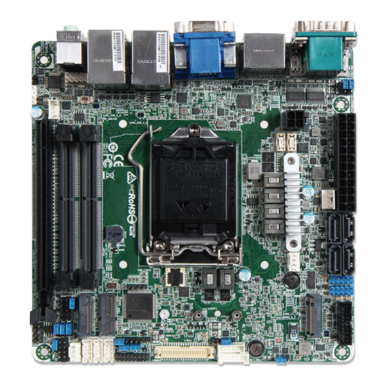
WADE-8212 4 Hardware Configuration 4.1 Jumpers and Connectors This chapter indicates jumpers’, headers’ and connectors’ locations. Users may find useful information related to hardware settings in this chapter. Copyright © Portwell 2020 WADE-8212 User's Guide... -
Page 15: Jumpers Settings
4.2 Jumpers Settings For users to customize WADE-8212’s features. In the following sections, Short means covering a jumper cap over jumper pins; Open or N/C (Not Connected) means removing a jumper cap from jumper pins. Users can refer to Figure 1 for the Jumper allocations. - Page 16 Buzzer SIO_AT1 Digital Input/Output Pin Header(JGPIO1) Digital Input/Output Default Value Setting(JGPIO_SET1) M.2 M key Socket M.2 E key Socket PWR LOSS Header(PWR_LOSS1) 3W Audio AMP Output Wafer SPDIF Header PWR_BAT1 Clear CMOS Header(CLRMOS2) Copyright © Portwell 2020 WADE-8212 User's Guide...
- Page 17 Bottom:USB 3.1 Ports(USB3_5_6) Top:RJ45 LAN port(LAN1) Bottom:USB 3.1 Ports(USB3_1_2) Top: D-Sub Port(VGA) Top: Display Port (DP2) Bottom: HDMI Port(HDMI) Top: COM Port 1(RS232/422/485)* Bottom: COM Port 2(RS232/422/485)* Back Side: SIM Card Socket(SIM1) MCU Connector(MCU_CON1) Copyright © Portwell 2020 WADE-8212 User's Guide...
- Page 18 1: COM Port PWR Setting Jumpers(COM 1~2) PWR_COM1 (For COM Port1) PWR_COM2 (For COM Port2) 1-2:+5V 2-3:+12V 2: 4-pin ATX Power Input/Output Connector 3: 24-pin ATX Power Input Connector 4: SATA Power Output Connector Copyright © Portwell 2020 WADE-8212 User's Guide...
- Page 19 WADE-8212 5: SATA3 Connectors (SATA3_1~4) 6: USB2.0 Headers (USB2_8_9, USB2_11_12) 7: USB3.0 Header (USB3_3_4) Copyright © Portwell 2020 WADE-8212 User's Guide...
- Page 20 WADE-8212 8: M.2 Key-B Socket (M2B1) 29: M.2 Key-M Socket (M2M1) 30: M.2 Key-E Socket (M2E1) Copyright © Portwell 2020 WADE-8212 User's Guide...
- Page 21 WADE-8212 9: 4-Pin CPU FAN Connector (+12V) (CPU_FAN1) 10: Clear CMOS Header (CLRMOS1) 1-2:Normal 2-3:Clear CMOS 11: Chassis Intrusion Headers (CI1) CI1: Close:Active Case Open Open:Normal Copyright © Portwell 2020 WADE-8212 User's Guide...
- Page 22 WADE-8212 12: Backlight Power Select (LCD_BLT_VCC) (BKT_PWR1) 1-2:LCD_BLT_VCC:+5V 2-3:LCD_BLT_VCC:+12V 13: Inverter Power Control Wafer (BLT_PWR1) 14: Backlight Volume Control (BLT_VOL1) Copyright © Portwell 2020 WADE-8212 User's Guide...
- Page 23 WADE-8212 15: LVDS Panel Connector * PD (Panel Detection): Connect this pin to LVDS Panel’s Ground pin to detect Panel detection. 16: Panel Power Select (LCD_VCC) (PNL_PWR1) 1-2:LCD_VCC:+3V 2-3:LCD_VCC:+5V 4-5:LCD_VCC:+12V Copyright © Portwell 2020 WADE-8212 User's Guide...
- Page 24 WADE-8212 17: LVDSBL1 Open : Protect LCD_VCC Short : No Protect LCD_VCC LVDSBL2 Open : Protect LCD_BLT_VCC Short : No Protect LCD_BLT_VCC 18: Chassis Intrusion Headers (CI2) CI2: Close:Active Case Open Open:Normal Copyright © Portwell 2020 WADE-8212 User's Guide...
- Page 25 WADE-8212 19: TPM Header 20: Backlight Control Level (CON_LBKLT_CTL) (BLT_PWM1) 1-2 : From eDP PWM to CON_LBKLT_CTL 2-3 : From LVDS PWM to CON_LBKLT_CTL 21: COM Port Headers (COM3, 4, 5) (RS232) Copyright © Portwell 2020 WADE-8212 User's Guide...
- Page 26 WADE-8212 22: 4-Pin Chassis FAN Connector (+12V) 23: System Panel Header 24: COM Port PWR Setting Jumpers(COM 3~4) PWR_COM3 (For COM Port3) PWR_COM4 (For COM Port4) PWR_COM5 (For COM Port5) 1-2:+5V 2-3:+12V Copyright © Portwell 2020 WADE-8212 User's Guide...
- Page 27 WADE-8212 25: Buzzer 26: SIO_AT1 Open:ATX Mode Short:AT Mode 27: Digital Input/Output Pin Header (JGPIO1) Copyright © Portwell 2020 WADE-8212 User's Guide...
- Page 28 WADE-8212 28: Digital Input / Output Default Value Setting (JGPIO_SET1) 1-2:Pull-High 2-3:Pull-Low 31: PWR LOSS Header (PWR_LOSS1) Short:Power Loss Open:no Power Loss 32: 3W Audio AMP Output Wafer Copyright © Portwell 2020 WADE-8212 User's Guide...
- Page 29 33: SPDIF Header 34: PWR_BAT1 Open:Normal Short:Charge Battery 35: Clear CMOS Header (CLRMOS2) Open:Normal Short: Auto Clear CMOS (Power Off) 36: Battery Connector 37: Audio Output Green - Line Out Pink - Mic In Copyright © Portwell 2020 WADE-8212 User's Guide...
- Page 30 * Please refer to below table for the pin definition. In addition, they can be adjusted in BIOS setup utility > Advanced Screen > Super IO Configura- tion. You may refer to our user manual for details. Copyright © Portwell 2020 WADE-8212 User's Guide...
- Page 31 WADE-8212 Copyright © Portwell 2020 WADE-8212 User's Guide...
-
Page 32: Signal Descriptions
WatchDog timer:"); scanf("%d", &WDTimer); ShowError(bSuccess = AsrLibWDSetConfig(WDTimer)); ShowError(bSuccess = AsrLibWDTrigger()); char Key = 0; int CurrentTime = 0; int WaitSeconds = WDTimer; while (WaitSeconds) { ShowError(CurrentTime = AsrLibWDCounter()); WaitSeconds++; while (1) while (kbhit()) Copyright © Portwell 2020 WADE-8212 User's Guide... - Page 33 ShowError(bSuccess = AsrLibWDTrigger()); WaitSeconds = WDTimer; ShowError(CurrentTime = AsrLibWDCounter()); break; else if (Key == 'c') { AsrLibWDDisable(); WaitSeconds = 0; _tprintf(_T("\nWatchDog Disable")); break; if (WaitSeconds == 0) break; if (CurrentTime != AsrLibWDCounter()) { WaitSeconds--; Copyright © Portwell 2020 WADE-8212 User's Guide...
- Page 34 WADE-8212 printf("\rWatchDog timer %d, press 'r' to reset timer, 'c' to disable WatchDog.", WaitSeconds); CurrentTime = AsrLibWDCounter(); printf("\n"); Copyright © Portwell 2020 WADE-8212 User's Guide...
-
Page 35: Gpio Signal
PinCount = 8; int n = 0; SSCORE_GPIO_VALUE Values[8]; ::AsrLibGetSioGpioGroup(GP2x, Values, &PinCount); for (n = 0; n < PinCount; n++) { DisplayGpioString(&Values[n]); _tprintf(_T("\n")); int GPIOType = 0; printf("Input GPIOType:(1:GPIO_INPUT 2:GPIO_OUTPUT_LOW 3:GPIO_OUTPUT_HIGH)"); scanf("%d", &GPIOType); Copyright © Portwell 2020 WADE-8212 User's Guide... - Page 36 ShowError(bSuccess = AsrLibSetSioGpioValue((GP2x * 10) + 3, ESCORE_GPIO_OUTPUT_LOW)); ShowError(bSuccess = AsrLibSetSioGpioValue((GP2x * 10) + 4, ESCORE_GPIO_OUTPUT_LOW)); ShowError(bSuccess = AsrLibSetSioGpioValue((GP2x * 10) + 5, ESCORE_GPIO_OUTPUT_LOW)); ShowError(bSuccess = AsrLibSetSioGpioValue((GP2x * 10) + 6, ESCORE_GPIO_OUTPUT_LOW)); ShowError(bSuccess = AsrLibSetSioGpioValue((GP2x * 10) + 7, ESCORE_GPIO_OUTPUT_LOW)); Copyright © Portwell 2020 WADE-8212 User's Guide...
- Page 37 ShowError(bSuccess = AsrLibSetSioGpioValue((GP2x * 10) + 4, ESCORE_GPIO_OUTPUT_HIGH)); ShowError(bSuccess = AsrLibSetSioGpioValue((GP2x * 10) + 5, ESCORE_GPIO_OUTPUT_LOW)); ShowError(bSuccess = AsrLibSetSioGpioValue((GP2x * 10) + 6, ESCORE_GPIO_OUTPUT_HIGH)); ShowError(bSuccess = AsrLibSetSioGpioValue((GP2x * 10) + 7, ESCORE_GPIO_OUTPUT_LOW)); _tprintf(_T("New state\n")); _tprintf(_T("--------------------------------------\n")); Copyright © Portwell 2020 WADE-8212 User's Guide...
- Page 38 WADE-8212 ::AsrLibGetSioGpioGroup(GP2x, Values, &PinCount); for (n = 0; n < PinCount; n++) { DisplayGpioString(&Values[n]); Copyright © Portwell 2020 WADE-8212 User's Guide...
-
Page 39: System Resources
Intel® Q470E Chipset (Intel® GL82Q470E PCH) 6.2 Main Memory WADE-8212 provides 2x260 pin So-DIMM sockets. The maximum memory can be up to 64GB. Memory clock and related settings can be detected by BIOS via SPD interface. Watch out the contact and lock integrity of memory module with socket, it will impact on the system reliability. Follow normal procedures to install memory module into memory socket. -
Page 40: Installing The Single Board Computer
6.3.1 Chipset Component Driver WADE-8212 is based on Intel® Q470E chipset and desktop processors including Core™ i7 / i5 / i3 sku . It’s a new chipset that some old operating systems might not be able to recognize. To overcome this compatibility issue, for Windows Operating Systems such as Windows 8, please install its INF before any of other Drivers are installed. -
Page 41: Intel® Uhd Graphics 630
6.3.2 Intel® UHD Graphics 630 WADE-8212 has integrated Intel® UHD Graphics 630 which supports DirectX 12、OpenGL 4.5. It is the most advanced design to gain an outstanding graphic performance. WADE-8212 supports VGA, DP, HDMI, LVDS display output. This combination makes WADE-8212 an excellent performance hardware. -
Page 42: Bios Setup Items
The BIOS setup program provides a General Help screen. The menu can be easily called up from any menu by pressing <F1>. The Help screen lists all the possible keys to use and the selections for the highlighted item. Press <Esc> to exit the Help Screen. Copyright © Portwell 2020 WADE-8212... - Page 43 WADE-8212 Copyright © Portwell 2020 WADE-8212 User's Guide...
-
Page 44: Main
System Date The date format is <Day>, <Month> <Date> <Year>. Use [+] or [-] to configure system Date. System Time The time format is <Hour> <Minute> <Second>. Use [+] or [-] to configure system Time. Copyright © Portwell 2020 WADE-8212... -
Page 45: Advanced
WADE-8212 7.2.2 Advanced Use this menu to set up the items of special enhanced features Copyright © Portwell 2020 WADE-8212 User's Guide... - Page 46 WADE-8212 CPU Configuration CPU Configuration Parameters Copyright © Portwell 2020 WADE-8212 User's Guide...
- Page 47 Enable/Disable processor Turbo Mode(requires Intel Speed Step or Intel Speed Shift to ★Enabled ,Disabled Turbo Mode be available and enabled) ★Enabled ,Disabled CPU Thermal Throttling Enable CPU internal thermal control mechanisms to keep the CPU from overheating. Copyright © Portwell 2020 WADE-8212 User's Guide...
- Page 48 WADE-8212 Chipset Configuration Configure Chipset Settings Copyright © Portwell 2020 WADE-8212 User's Guide...
- Page 49 1024 x 600/18bit/1ch/LED, 800x600/18-bit/1-ch/CCFL Panel Type Selection Selection Panel Type 1280 x 1024/24bit/2ch/LED, 1024 x 768/24bit/1ch/LED, 1600 x 900/18bit/2ch/LED, 1366 x 768/24bit/1ch/LED, 1366 x 768/18bit/1ch/LED, 800 x 600/24bit/1ch/LED, 640 x 480/24bit/1ch/LED, 1024 x 768/18bit/1ch/LED, Copyright © Portwell 2020 WADE-8212 User's Guide...
- Page 50 Select the power state after a power failure. If [Power Off] is selected, the power ★Power Off ,Power On Restore on AC/Power Loss will remain off when the power recovers. If [Power On] is selected, the system will start to boot up when the power recovers. Copyright © Portwell 2020 WADE-8212 User's Guide...
- Page 51 AHCI mode. S.M.A.R.T stands for Self-Monitoring, Analysis, and Reporting ★Enabled, Disabled Hard Disk S.M.A.R.T system for computer hard disk drives to detect and report on various indicators of reliability. Copyright © Portwell 2020 WADE-8212 User's Guide...
- Page 52 Hot Plug Enable or disable Hot Plug for this port. ★Hard Disk Drive, Solid State Drive SATA Device Type Identify the SATA port is connected to Solid State Drive or Hard Disk Drive. Copyright © Portwell 2020 WADE-8212 User's Guide...
- Page 53 Enable or disable Hot Plug for this port. ★Disabled ,Enabled ★Hard Disk Drive, Solid State Drive SATA Device Type Identify the SATA port is connected to Solid State Drive or Hard Disk Drive. Copyright © Portwell 2020 WADE-8212 User's Guide...
- Page 54 WADE-8212 Super IO Configuration Configure Super IO Settings. Copyright © Portwell 2020 WADE-8212 User's Guide...
- Page 55 Enable or Disable COM4, IO=2E0h; IRQ=10; ★Enabled ,Disabled ★Disabled , Enabled WDT Timeout Reset Enable/Disable Watch Dog Timer timeout to reset system. WDT Timeout Reset[Enabled] WDT Initial Value (Sec.) Watch Dog Timer Initial Value to count down. ★255 Copyright © Portwell 2020 WADE-8212 User's Guide...
- Page 56 When disabled AMT BIOS Features are no longer supported and user is no longer able to AMT BIOS Features access MEBx Setup. ★Enable ,Disabled Note: This option does not disable Manageability Features in FW. ★Disabled, Enable USB Provisioning of AMT Enable/Disable of AMT USB Provisioning. Copyright © Portwell 2020 WADE-8212 User's Guide...
- Page 57 Activate Remote Assistance Process Setup. Activate Remote Assistance Process[Enable] OEM defined timeout for MPS connection to be established. CIRA Timeout 0-use the default timeout value of 60 seconds. ★0 255- MEBx waits until the connection succeeds Copyright © Portwell 2020 WADE-8212 User's Guide...
- Page 58 Enable/Disable WatchDog Timer. ★Disabled, Enable WatchDog [Enabled] OS Timer Set OS watchdog timer ★0 BIOS Timer Set BIOS watchdog timer ★0 ★Disabled, Enable ASF Sensors Table Adds ASF Sensor Table into ASF! ACPI Table Copyright © Portwell 2020 WADE-8212 User's Guide...
- Page 59 Description Options Change Secure Erase module behavior: ★Simulation, Real Secure Erase mode Simulated: Performs SE flow without erasing SSD Real: Erase SSD. ★Disabled, Enable Force Secure Erase Force Secure Erase on next boot Copyright © Portwell 2020 WADE-8212 User's Guide...
- Page 60 WADE-8212 OEM Flags Settings Configure OEM Flags Copyright © Portwell 2020 WADE-8212 User's Guide...
- Page 61 Hide Unconfigure ME Confirmation Prompt unconfiguration. MEBx OEM Debug Menu Enable OEMFlag Bit 14: Enable OEM debug menu in MEBx. ★Disabled, Enable ★Disabled, Enable Unconfigure ME OEMFlag Bit 15: Unconfigure ME with resetting MEBx password to default. Copyright © Portwell 2020 WADE-8212 User's Guide...
- Page 62 Resolution settings for MEBx display modes Feature Description Options ★Auto, 80x25,100x31 Non-UI Mode Resolution Resolution for non-UI text mode. UI Mode Resolution Resolution for UI text mode. ★Auto, 80x25,100x31 ★Auto, 640x480,800x600,1024x768 Graphics Mode Resolution Resolution for graphic mode. Copyright © Portwell 2020 WADE-8212 User's Guide...
- Page 63 WADE-8212 ACPI Configuration ACPI Parameters. Copyright © Portwell 2020 WADE-8212 User's Guide...
- Page 64 12,13,14,15,16,17,18,19,20, 21,22,23,24,25,26,27,28,20, RTC Alarm Minute Set Minute of RTC power on feature. 30,31,32,33,34,35,36,37,38, 39,40,41,42,43,44,45,46,47, 48,49,50,51,52,53,54,55,56, 57,58,59 ★0,1,2,3,4,5,6,7,8,9,10,11, 12,13,14,15,16,17,18,19,20, 21,22,23,24,25,26,27,28,20, RTC Alarm Second Set Second of RTC power on feature. 30,31,32,33,34,35,36,37,38, 39,40,41,42,43,44,45,46,47, 48,49,50,51,52,53,54,55,56, 57,58,59 Copyright © Portwell 2020 WADE-8212 User's Guide...
- Page 65 ★Enabled, UEFI Setup only Legacy USB Support are connected. Always enabled: Enable USB power in S0/S3/S4/S5, Default setting: Enable USB power ★Default setting ,Always Enabled USB Power Control in S0/S3, disable USB power in S4/S5. Copyright © Portwell 2020 WADE-8212 User's Guide...
- Page 66 WADE-8212 Trusted Computing Trusted Computing Settings Copyright © Portwell 2020 WADE-8212 User's Guide...
- Page 67 TPM1.2 will restrict support to TPM1.2 devices,TPM2.0 will restrict support to TPM2.0 ★Auto ,TPM1.2,TPM2.0 Device Select devices, Auto will support both with the default set to TPM2.0 devices if not found, TPM1.2 devices will be enumerated Copyright © Portwell 2020 WADE-8212 User's Guide...
-
Page 68: H/W Monitor
WADE-8212 7.2.3 H/W Monitor Copyright © Portwell 2020 WADE-8212 User's Guide... - Page 69 ★Level 9Level 1, Level 2, Level 3, Level 4, Level 5, Level 6, Target Fan Speed The higher the level, the higher the fan speed. Level 7, Level 8, ★Disabled, Enabled Case Open Feature Enable or disable the feature of Case Open. Copyright © Portwell 2020 WADE-8212 User's Guide...
-
Page 70: Security
Set or change the password for the user account. Users are unable to change the User Password settings in the UEFI Setup Utility. Leave it blank and press enter to remove the password. Copyright © Portwell 2020 WADE-8212 User's Guide... - Page 71 Install default Secure Boot keys Please install default secure boot keys if it’s the first time you use secure boot. Clear Secure Boot Keys Force System to Setup Mode- clear all Secure Boot Variables. Change takes effect after reboot Copyright © Portwell 2020 WADE-8212 User's Guide...
- Page 72 WADE-8212 Key Management Copyright © Portwell 2020 WADE-8212 User's Guide...
- Page 73 1.Publuc Key Certificate: Key Exchange Keys a)EFI_SIGNATURE_LIST Authorized Signatures b) EFI_CERT_X509 (DER) Forbidden Signatures c) EFI_CERT_RSA2048 (bin) Authorized TimeStamps d)EFI_CERT_SHAXXX 2.Authenticated UEFI Variable OsRecovery Signatures 3.EFI PE/COFF Image(SHA256) Key Source: Factory, External, Mixed Copyright © Portwell 2020 WADE-8212 User's Guide...
-
Page 74: Boot
Select whether Num Lock should be turned on or off when the system boots up. Full Screen Logo Enable to display the boot logo or disable to show normal POST messages. ★Disabled, Enabled Copyright © Portwell 2020 WADE-8212 User's Guide... - Page 75 Launch Storage OpROM Policy only to run those that support legacy option ROM only. Select Do not launch to ★Legacy only ,Do not launch, UEFI only not execute both legacy and UEFI option ROM. Copyright © Portwell 2020 WADE-8212 User's Guide...
-
Page 76: Exit
Load UEFI Default values for all the setup question. Load UEFI Defaults F9 key can be used for this operation. Attempts to Launch EFI Shell application (Shell.efi) from one of the available Launch EFI Shell from filesystem device filesystem devices. Copyright © Portwell 2020 WADE-8212 User's Guide... -
Page 77: Troubleshooting
WADE-8212 8 Troubleshooting This section provides a few useful tips to quickly get WADE-8212 running with success. This section will primarily focus on system integration issues, in terms of BIOS setting, and OS diagnostics. Hardware Quick Installation ATX Power Setting Unlike other Single board computer, WADE-8212 supports ATX only. -
Page 78: Bios Setting
To make sure that you have a successful start with WADE-8212, it is recommended, when going with the boot-up sequence, to hit “delete ” or ” Esc” key and enter the BIOS setup menu to tune up a stable BIOS configuration so that you can wake up your system far well. -
Page 79: Faq
Question: I forgot my password of system BIOS, what am I supposed to do? Answer: You can switch off your power supply then find the J10 on the WADE-8212 board to set it from 1-2 short to 2-3 short and wait 5 seconds to clean your password then set it back to 1-2 short to switch on your power supply. - Page 80 WADE-8212 Question: How to update the BIOS file of WADE-8212? Answer: 1. Please visit web site of Portwell download center as below hyperlink http://www.portwell.com.tw/support/download_center.php Registering an account in advance is a must. (The E-Mail box should be an existing Company email address that you check regularly.) http://www.portwell.com.tw/member/newmember.php...
- Page 81 WADE-8212 6. Select “xxxx.23A” file then start updating BIOS. Copyright © Portwell 2020 WADE-8212 User's Guide...
- Page 82 WADE-8212 7. When you see the “Programming success” message, which means the BIOS update processes finished. Please cut the AC power off wait for 10 seconds before powering on. Copyright © Portwell 2020 WADE-8212 User's Guide...
- Page 83 WADE-8212 Question: What are the display options while using WADE-8212 board? Answer: - The WADE-8212 supports VGA、HDMI、DP and LVDS display output. Note: Please visit our Download Center to get the Catalog, User manual, BIOS, and driver files. http://www.portwell.com.tw/support/download_center.php If you have other additional technical information or request which is not covered in this manual, please fill in the technical request form as below hyperlink.
-
Page 84: Portwell Software Service
WADE-8212 9 Portwell Software Service 1. If you have customized requirements of BIOS, you can contact person of our company or branch. 2. If you have requirements of WDT、GPIO APP, you can contact our headquarter or branch, and we can render you assistance on developing. -
Page 85: Industry Specifications
WADE-8212 10 Industry Specifications 10.1 Industry Specifications The list below provides links to industry specifications that apply to Portwell modules. Low Pin Count Interface Specification, Revision 1.0 (LPC) http://www.intel.com/design/chipsets/industry/lpc.htm Universal Serial Bus (USB) Specification, Revision 2.0 http://www.usb.org/home PCI Specification, Revision 2.3 https://www.pcisig.com/specifications...
Need help?
Do you have a question about the WADE-8212 and is the answer not in the manual?
Questions and answers