
Subscribe to Our Youtube Channel
Related Manuals for Leuze LBK S-01


Summary of Contents for Leuze LBK S-01
- Page 1 Installation instructions Sensor LBK S-01 Sensor LBK SBV Controller ISC We reserve the right to make technical changes EN•2022-12-15•50149168...
-
Page 2: Installation Instructions
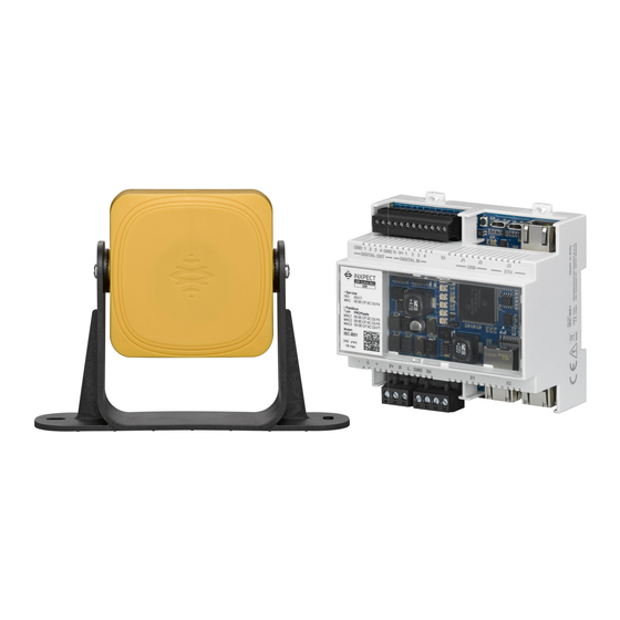
Keep the sensor field of view unobstructed. CE Conformity The manufacturer, Inxpect SpA, states that LBK S-01 System and LBK SBV System (Safety Radar Equipment) complies with the 2014/53/EU and 2006/42/EC directives. The full EU declaration of conformity text is available on the company's website at the address: www.leuze.com (from the... - Page 3 LBK S-01 sensors Part Description Sensor Screws for fastening the sensor at a specific inclination Mounting bracket Status LED Connectors for connecting the sensors in a chain and to the controller Leuze electronic GmbH + Co. KG Sensor LBK S-01...
- Page 4 LBK SBV-01 status LED Status Meaning Steady blue Sensor is working. No motion detected. Flashing blue Sensor is detecting motion. Not available if the sensor is in muting. Purple Firmware update conditions Error conditions Leuze electronic GmbH + Co. KG Sensor LBK S-01...
- Page 5 Article Description 50143389 KD DN-M12-5W-P1-150 Connection cable, M12 angled, 5-pin, 15m 50114696 KB DN/CAN-5000 BA Connection cable, M12 axial, 5-pin, 5m 50114699 KB DN/CAN-10000 BA Connection cable, M12 axial, 5-pin, 10m Leuze electronic GmbH + Co. KG Sensor LBK S-01...
- Page 6 Note: the maximum operating temperature of the cables must be at least 70 °C. Note: use only copper wires with a minimum gauge of 18 AWG and a torque of 0.62 Nm. Leuze electronic GmbH + Co. KG Sensor LBK S-01...
-
Page 7: Installation
6. Select the sensor type and the number of sensors. 7. (only for LBK S-01 System) Set the working frequency. If the system is installed in one of the countries with national restrictions, select the restricted band, otherwise select the full band. - Page 8 3. If the muting is managed, click Muting and assign the sensors to the groups according to the logic of the digital inputs. 4. Click APPLY CHANGES to save the configuration. Leuze electronic GmbH + Co. KG Sensor LBK S-01...
- Page 9 Installation Install LBK S-01 sensors on the floor Note: for installation with Metal protector kit (product code 50143346), see the instructions supplied with the kit. 1. Position the sensor as indicated in the configuration report and fasten the bracket with two tamper-proof screws directly onto the floor or another support.
- Page 10 Installation 3. Direct the sensor up to the desired inclination. Note: a notch is equal to 10° of inclination. 4. Tighten the screws. Leuze electronic GmbH + Co. KG Sensor LBK S-01...
- Page 11 Installation Install LBK S-01 sensors on the machinery Note: if the sensor is installed on parts that vibrate and objects are present in the field of view, the sensor could generate undesired alarms. 1. Position the sensor as indicated in the configuration report and fasten the bracket with two screws to a machinery support.
- Page 12 Note: a notch is equal to 10° of inclination. 5. Tighten the screws. (only for LBK S-01 sensors) Connect the controller to the sensors and assign the IDs 1. Decide if the controller will be positioned at the end of the chain or inside of it (see Chain examples on page 19).
- Page 13 14. Repeat from step 8 to connect another sensor, or click TERMINATE to conclude the procedure. Note: the maximum length of the CAN bus line from the controller to the last sensor in the chain is 30 m. Leuze electronic GmbH + Co. KG Sensor LBK S-01...
- Page 14 Make sure the support does not inhibit machinery commands. 2. With an Allen key, loosen the screw at the bottom to pan the sensor. Note: to avoid damaging the bracket, loosen the screw completely before panning the sensor. Leuze electronic GmbH + Co. KG Sensor LBK S-01...
- Page 15 Installation 3. Pan the sensor until it reaches the desired position. Note: a notch is equal to 10° of inclination. 4. Tighten the screw. Leuze electronic GmbH + Co. KG Sensor LBK S-01...
- Page 16 Installation 5. Loosen the tamper-proof screws to tilt the sensor. 6. Direct the sensor up to the desired inclination. Note: a notch is equal to 10° of inclination. Leuze electronic GmbH + Co. KG Sensor LBK S-01...
- Page 17 The bracket that allows rotation around the z-axis (roll) is an accessory in the package. To mount it: 1. Unscrew the screw at the bottom and remove the bracket with the sensor and the aligning ring. Leuze electronic GmbH + Co. KG Sensor LBK S-01...
- Page 18 (only for LBK SBV-01 sensors) Connect the controller to the sensors 1. With the cable validator tool (downloadable, only for LBK SBV System, from the site www.leuze.com), decide if the controller will be positioned at the end of the chain or inside it (see Chain examples on the next page).
- Page 19 Note: to save the PDF, a printer must be installed on the computer. 3. Ask the authorized person for a signature. What to do next Follow the instructions in the manual to validate the safety functions and manage the configuration. www.leuze.com Leuze electronic GmbH + Co. KG Sensor LBK S-01...
Need help?
Do you have a question about the LBK S-01 and is the answer not in the manual?
Questions and answers